VISTEK V1636 User manual

V1636
24-bitAudioDigital To Analog
Converter
UserGuide
Issue:4.0
©Pro-BelLtd
www.pro-bel.com

VistekV163624-bitAudioDigital
ToAnalog Converter
2 HU-V1636
Contents
1Description 3
2Installation 4
2.1 RearPanel Connections 4
2.2 MaximumOutputLevel Adjustment 7
3Operation 8
3.1 FrontPanel ControlsandIndicators 8
3.1.1 RemoteControl Access and PowerIndicators 8
3.1.2 Sampling RateIndicators 9
3.1.3 Input StatusIndicators 9
3.1.4 CharacterDisplay 9
3.1.5 ParameterSelection Controls 9
3.2 AdjustmentofOperatingParameters 9
3.2.1 General 9
3.2.2 DelayAdjustment 10
3.2.3 A/BSwap 11
3.2.4 Test Tone 11
4DartInterface 12
4.1 General 12

VistekV163624-bitAudioDigital
ToAnalog Converter
Issue 4.0 3
1 Description
The V1636isabroadcastquality24-bitaudiodigitaltoanalog converterwhichformspartof
the VistekV1600rangeofinterfaceproducts.Itisa3U high cardwhichisfittedintoeithera
V1601 orV1603 rack,fromwhichitreceivesitspower.Apassiverearmodulewithscrew
terminalconnections,isrequiredforall signalinterconnections.
The unitacceptstwoAES-3digitalstereo audio inputsand convertsthesesignalsto4
differentialmono analog outputsintwopairs.The V1636isfullycompatiblewiththe Vistek
DART remotesystem,allowing statusinformation tobe readand controlsettingsinvoked bya
DARTcompatiblerackcontroller.
INPUTS:
·2xAES3-1992balanced110Wdigitalaudiochannels,Z
in =110W(or75W
unbalancedwithspecialrearmodule).
·Samplingfrequenciesof32-96kHzaresupported.
·AES inputsAand Bcan be differentsamplefrequencies-asynchronoussample
rateconversiontoaninternalsamplerateof 48kHzisperformedontheinputs.
OUTPUTS:
·4xAnalog differentialquasi-balanced outputswithZout <50W(V1636)orZout<
18W(V1636ARD)
·MaxOutput level:0dBFS=+28dBu.Output leveladjustablebyon-cardswitches
from0dBFS=+14dButo0dBFS=+28dBuin1dBsteps.
FUNCTIONS:
·PanelSelectable/DARTcontrolled Delay from0msto1250msmaybe applied to
theoutputs. All outputsaresubjecttothesamedelayvalue.
·PanelSelectable/DART controlled A/BSwap transposesthe AESinputstreams.
·PanelSelectable/DARTcontrolled TestTone of997Hzat -18dBumaybe applied
toeitherorbothAorBchannelpairanalog outputs
·ControlsourcemaybePanelswitches(LOCAL mode)orDART (REMOTE mode)
·The V1636 respondstode-emphasis(50msorCCITT)code embedded inthe
AESChannelStatus.

VistekV163624-bitAudioDigital
ToAnalog Converter
4 HU-V1636
2 Installation
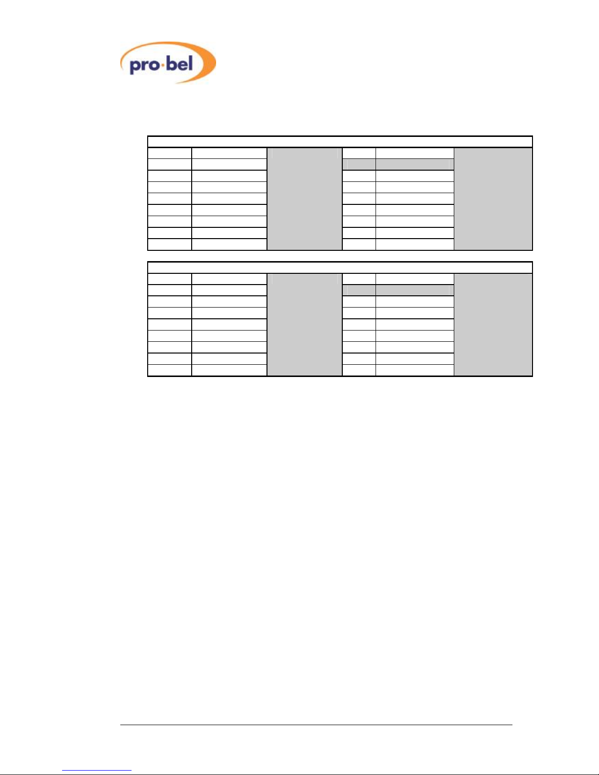
2.1 RearPanelConnections
The standard3U Screwterminalrearpanelisshownbelow. Other3U and 1U panelvariants
withscrewterminaland/orBNC connectorsaresimilarlymarked.Table2.1.1describesthe
connectionstotheunitwhen thesepanelsareused.
NotesonTable2.1.1:
1.Certainconnectionsare reserved.Do notconnectanything tothese
connections.
2.Grounds/screens(S)areconnectedtochassison alloutputsandinputsand
shouldbeconnectedtoall cablescreenstominimizehumand noise.
3.Neither(+or-)analogoutputshouldbe grounded.
Table2.1.2describesconnectionstothe unitwhen D-type panelsareused.
NotesonTable2.1.2:
No connectmeansdonotconnectthispintoanything.
L/AES
R
+
-
S
-
+
+
S
-
+
-
S
-
+
+
-
S
-
+
+
-
S
-
+
L/AES
R
L/AES
R
L/AES
R
AES
REF.
A
B
A
B
TRACK
VIDEO
REF

VistekV163624-bitAudioDigital
ToAnalog Converter
Issue 4.0 5
Table2.1.1
DescriptionofV1635rear panelconnectionsforstandardrear panelassemblies
SIGNAL SOURCE COMMENTS
name
POWER Rack PWRHeader +15Vnominal (9-35V)at 10Wmax
DARTbus Rack DARTheader VistekDARTRack controller
A
3
(IN)
L/AES
(+/
-
)
ExternalAES source
AES3/AES3iddigitalinput for channelpairA
R
(+/
-
)
DoNot Connect
Reserved
B
3
(IN)
L/AES
(+/
-
)
ExternalAES source
AES3/AES3iddigitalinput for channelpairB
R
(+/
-
)
DoNot Connect
Reserved
A
4
(OUT)
L/AES
(+/
-
)
V1636
LAnalog output for channelpairA
R (+/-) V1636 RAnalog output for channelpairA
B
4
(OUT)
L/AES(+/
-
)
V1636
LAnalog output for channelpairB
R (+/-) V1636 RAnalog output for channelpairB
AES
3
(IN)
Donot connect
Reserved
REF
VIDEO
3
(IN)
Donot connect
Reserved
REF
TRACK
3
(IN)
Donot connect
Reserved
VistekV163624-bitAudioDigital
ToAnalog Converter
6 HU-V1636
Table2.1.2
DescriptionofV1635rear panelconnectionsforD-typerearpanelassemblies
D15FInputconnector
Pin Signal Pin Signal
1 AESAin-
2 Noconnect 9 AESAin+
3 GND 10 Noconnect
4 AESRefin- 11 GND
5 AESBin- 12 AESRefin+
6 Noconnect 13 AESBin+
7 GND 14 Noconnect
8 GND
15 GND
D15FOutputconnector
Pin Signal Pin Signal
1 Aleft out -
2 Aright out-9 Aleft out +
3 GND 10 Aright out+
4 GND 11 GND
5 Bleft out - 12 GND
6 Bright out- 13 Bleft out +
7 GND 14 Bright out+
8 GND
15 GND

VistekV163624-bitAudioDigital
ToAnalog Converter
Issue 4.0 7
2.2 Maximum OutputLevelAdjustment
The V1636 hastworotaryHexSwitchesforadjusting theMOL(Maximum Output Level)of
eachof the channelpairsAand B.Looking at theV1636withthe Euroconnectoron the right
hand side, the rightswitchisforchannelpairA(Land R)and the leftswitchisforchannelpair
B(LandR).The locationofthe MOLswitchesisshownon thefigurebelow. These switches
adjustthe analog MOLcorrespondingto0dBFSdigitalinputin1dBstepsfrom+14dButo
+28dBu.Thetablebelowshowsthe correspondencebetween the 16 switchpositionsand
themaxoutput levelsettingfortheV1636.
Switchsetting MOL(dBu)
0 +14
1 +15
2 +16
3 +17
4 +18
5 +19
6 +20
7 +21
8 +22
9 +23
A +24
B +25
C +26
D +27
E +28
F reserved

VistekV163624-bitAudioDigital
ToAnalog Converter
8 HU-V1636
3 Operation
3.1 FrontPanelControlsand Indicators
3.1.1 RemoteControl Access andPowerIndicators
The green V+LEDislitwhen the unit’son-boardpowersupplyisdelivering voltage.The
yellowREM LEDislitwheneverthe unitisaccessed bythe RackControllerforthe DART
remotesystem
REM +V
V1636
Audio
DAC
RemoteControl AccessandPower indicators
Sampling rateindicators
32k 44k1
48k
Rem Local
Parameter
Selection Controls
AI/P
A/BSwap
Select
CharacterDisplay
7. 7. 7.
Input status indicators
BI/P
Front Panel
Rear Connector
A B

VistekV163624-bitAudioDigital
ToAnalog Converter
Issue 4.0 9
3.1.2 SamplingRateIndicators
Becausethe samplingratesofinputAESAand Btothe V1636 DACmaybe different,the
inputsareasynchronouslyconverted toan internalsample rateof48kHzwhichisnotuser
adjustable.The48kHzLEDwill thereforealwaysbe litwhen the cardisoperating.
3.1.3 InputStatusIndicators
The AI/Pand BI/PLEDsrespectivelyindicatethe statusoftheAES inputsAand B.Ifthe
AESinput isvalid,thecorrespondingLEDislit, otherwisethe LEDisoff.
3.1.4 CharacterDisplay
Used fordisplayingparameterswhichhavenumericoralphanumericvalues
3.1.5 ParameterSelectionControls
Theseareused forselection of, and adjustmentof,operating parameterswhen the
REM/LOCAL switchissetto LOCAL.
3.2 AdjustmentofOperatingParameters
3.2.1 General
The V1636 hastwo pages (Page0 and Page1)ofpaneladjustmentmodes,eachpage
allowsadjustmentofone ormore parameters.Conceptuallythe procedureisnotunlike
settingadigitalalarmclockorwatch.
·Paneladjustmentpagescan onlybe invoked ifthe REM/LOCAL switchon the panel
isset to LOCAL.
·Pressing the SELECT button on itsowninvokesthe paneladjustmentmodesof
Page0
·Pressing the SELECT button whileholdinginthe pbutton invokesthe panel
adjustmentmodesofPage 1.Inotherwords,the pbutton behaveslikea
‘SHIFT’keyon atypewriterwhen selecting pagesofadjustmentmodes.By this
analogy,Page 0correspondstolowercaseand Page1 correspondstoupper
caseletterson atypewriter.
·Onceanypanel adjustmentpage hasbeen selected,repeated pressing ofthe
SELECT button allowsthe usertoscrollthroughthe variousparametersavailable
on thepage.ArowofLEDsabovethe SELECT button indicateswhich
parameter ispresentlyselectedforadjustment.
·Foranygivenparameterselectedforadjustment, thevalueofthe parametermay
be increased ordecreased bypressing the por qkeysrespectively. The value
ofthe parameterisindicated eitheron the characterdisplayorthe respectivesets
ofLEDsabovethecharacterdisplay.

VistekV163624-bitAudioDigital
ToAnalog Converter
10 HU-V1636
·Holdingthe or por qbuttonsdownwillcausethevalue of the parametertoauto
incrementandautodecrementrespectively.The longerthebutton ishelddown,
thefastertherateof autoincrement orautodecrement.
·Onceaparameterhasbeen adjusted tothedesired value,the PanelAdjustment
mode isexited bypressing the SELECT buttonuntil allfourofthe LEDsabove
the SELECT button areoff.NOTE: OnlywhenPanelAdjustmentmodeis
exited willtheparameteradjustmentstakeeffect.
·The V1636hasnon volatilememory storage thatautomaticallysavesthe values
of allthe operating parameterssothaton power-up, the lastused settingswillbe
invoked.
Thefollowing tableindicatestheavailablePanelAdjustmentmodesonthetwopages.
LED
indicator Page0 Page1
Parameter Adjust range Parameter Adjust range
Delay Delay 0msto1250s Test Tone A,BOff/A,Bon
- - -
- - -
A/BSwap A/BSwap Normal/Swapped -
3.2.2 DelayAdjustment
·Afixed delaymaybe applied toallfouranalog channelsasagroup and the
presentsetting maybe seen on the characterdisplayasanumberwhen Page0
PanelAdjustmentmodehasbeenentered and Delay selectedasaparameter.
·By PanelSelection the delayvalue maybe adjusted from0msto1.25 seconds.
Adjustmentfrom0to99msisin1mssteps, and adjustmentfrom100msupwards
isin10mssteps.From0to999ms,the delayvalue isdisplayed inmsand from
1.0supwardsitisdisplayedinseronds.
·TheDART interfacecancontrolthedelayin1msstepsacross the range.
·Theminimumthroughputdelayofthe V1636isless than1ms.
Note:changingthefixeddelaywillcauseatemporarydisruptionofaudiofornotless
thanthevalueofthenewdelaysetting.

VistekV163624-bitAudioDigital
ToAnalog Converter
Issue 4.0 11
3.2.3 A/BSwap
·Atransposition ofAESAand AESBinputsmaybe invoked and the present
setting maybe seen on the characterdisplayasalettercombination when Page
0PanelAdjustmentmode hasbeen entered and A/BSwap selected asa
parameter.
·When AES inputchannelpairsAand Barenormallyconverted toAL/ARand
BL/BRanalog outputpairsrespectively,the A/BSwap parameterisindicatedon
thecharacterdisplayas A-A.
·When AESinputchannelpairsaretransposed sothatAESAconvertstoBL/BR
and AES BconvertstoAL/ARanalog outputpairsrespectively,the A/BSwap
parameterisindicatedonthecharacterdisplayas A-b .
3.2.4 TestTone
·Atesttone of997Hz0dBumaybe invoked on the L/RchannelsofeitherorbothA
and Bchannelpairoutputsand the presentsetting maybeseen on the character
displayasanumbercombination when Page1 PanelAdjustmentmode hasbeen
enteredand TestTone selectedasaparameter.
·ThetablebelowexplainstheavailableTestToneselections
Display Test Tones
00 Notest tonesselected
10 Test toneonchannelpairAonly
01 Test toneonchannelpairBonly
11 Test toneonbothchannelpairs

VistekV163624-bitAudioDigital
ToAnalog Converter
12 HU-V1636
4 DartInterface
4.1 General
The V1636 isaClass 4DARTmodulewhichhasaserialEEPROMforreading and writing
carddetailsthrough the DARTbusinthe samemannerasotherV1600range cards.In
addition the unithasseveralread and writeregisters,detailsofwhichmaybe found in
document scsm1636.doc
Table of contents
Other VISTEK Media Converter manuals


