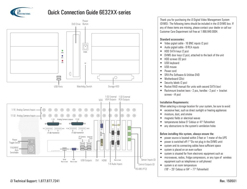
visual engineering Guardian VIP User manual

Guardian VIP May 2017
Visual Engineering
Video solutions. Integrated
visualengineering.co.uk
Page 1
Guardian VIP
User Manual v2.0
Rapid Deployable
Security System

Guardian VIP May 2017
Visual Engineering
Video solutions. Integrated
visualengineering.co.uk
Page 2
Table of Contents . . . . . . . . . . . . . . . . . . . . . . . . . . . . . . . . . . . . . . . . . . . . . . . . . . . . . . . . . . . . . . . . . . . . . . . 2
Change History . . . . . . . . . . . . . . . . . . . . . . . . . . . . . . . . . . . . . . . . . . . . . . . . . . . . . . . . . . . . . . . . . . . . . . . . . 4
About the User Manual . . . . . . . . . . . . . . . . . . . . . . . . . . . . . . . . . . . . . . . . . . . . . . . . . . . . . . . . . . . . . . . . . . 5
User Manual Part Number . . . . . . . . . . . . . . . . . . . . . . . . . . . . . . . . . . . . . . . . . . . . . . . . . . . . . . . . . . . . . . . . . . 5
Warranty and Support . . . . . . . . . . . . . . . . . . . . . . . . . . . . . . . . . . . . . . . . . . . . . . . . . . . . . . . . . . . . . . . . . . . 5
Introduction to the Guardian VIP System . . . . . . . . . . . . . . . . . . . . . . . . . . . . . . . . . . . . . . . . . . . . . . . . . . . 6
The Guardian VIP Kit . . . . . . . . . . . . . . . . . . . . . . . . . . . . . . . . . . . . . . . . . . . . . . . . . . . . . . . . . . . . . . . . . . . . 7
Kit Contents . . . . . . . . . . . . . . . . . . . . . . . . . . . . . . . . . . . . . . . . . . . . . . . . . . . . . . . . . . . . . . . . . . . . . . . . . . . . . . 7
Key Components . . . . . . . . . . . . . . . . . . . . . . . . . . . . . . . . . . . . . . . . . . . . . . . . . . . . . . . . . . . . . . . . . . . . . . . . . . 8
Part Numbers and Labels . . . . . . . . . . . . . . . . . . . . . . . . . . . . . . . . . . . . . . . . . . . . . . . . . . . . . . . . . . . . . . . . 8
Default IP Addresses . . . . . . . . . . . . . . . . . . . . . . . . . . . . . . . . . . . . . . . . . . . . . . . . . . . . . . . . . . . . . . . . . . . . . . . 9
Getting Started with Operator’s Base Station . . . . . . . . . . . . . . . . . . . . . . . . . . . . . . . . . . . . . . . . . . . . . . 10
Connecting the Base Station . . . . . . . . . . . . . . . . . . . . . . . . . . . . . . . . . . . . . . . . . . . . . . . . . . . . . . . . . . . . . . . 10
Switching the Base Station on . . . . . . . . . . . . . . . . . . . . . . . . . . . . . . . . . . . . . . . . . . . . . . . . . . . . . . . . . . . . . . 11
Base Station Front Panel LEDs. . . . . . . . . . . . . . . . . . . . . . . . . . . . . . . . . . . . . . . . . . . . . . . . . . . . . . . . . . . . . . 12
VIP Panic Alarm at the Base Station . . . . . . . . . . . . . . . . . . . . . . . . . . . . . . . . . . . . . . . . . . . . . . . . . . . . . . . . . 12
. . . . . . . . . . . . . . . . . . . . . . . . . . . . . . . . . . . . . . . . . . . . . . . . . . . . . . . . . . . . . . 12
Batteries. . . . . . . . . . . . . . . . . . . . . . . . . . . . . . . . . . . . . . . . . . . . . . . . . . . . . . . . . . . . . . . . . . . . . . . . . . . . . . 13
Battery Status. . . . . . . . . . . . . . . . . . . . . . . . . . . . . . . . . . . . . . . . . . . . . . . . . . . . . . . . . . . . . . . . . . . . . . . . . . . . 13
Dual Battery Pack. . . . . . . . . . . . . . . . . . . . . . . . . . . . . . . . . . . . . . . . . . . . . . . . . . . . . . . . . . . . . . . . . . . . . . . . . 14
Dummy Battery Pack. . . . . . . . . . . . . . . . . . . . . . . . . . . . . . . . . . . . . . . . . . . . . . . . . . . . . . . . . . . . . . . . . . . . . . 14
Battery Extension Cables . . . . . . . . . . . . . . . . . . . . . . . . . . . . . . . . . . . . . . . . . . . . . . . . . . . . . . . . . . . . . . . . . . 14
Battery Charging . . . . . . . . . . . . . . . . . . . . . . . . . . . . . . . . . . . . . . . . . . . . . . . . . . . . . . . . . . . . . . . . . . . . . . . . . 15
. . . . . . . . . . . . . . . . . . . . . . . . . . . . . . . . . . . . . . . . . . . . . . . . . . . . . . . . . . . . . . . . . . . 16
Logging in to the Operator’s laptop . . . . . . . . . . . . . . . . . . . . . . . . . . . . . . . . . . . . . . . . . . . . . . . . . . . . . . . . . 16
CCTV Nodes. . . . . . . . . . . . . . . . . . . . . . . . . . . . . . . . . . . . . . . . . . . . . . . . . . . . . . . . . . . . . . . . . . . . . . . . . . . 17
Installing a CCTV Node . . . . . . . . . . . . . . . . . . . . . . . . . . . . . . . . . . . . . . . . . . . . . . . . . . . . . . . . . . . . . . . . . . . . 17
Installing a Battery into the CCTV node . . . . . . . . . . . . . . . . . . . . . . . . . . . . . . . . . . . . . . . . . . . . . . . . . . . . . . 18
CCTV Node Positioning . . . . . . . . . . . . . . . . . . . . . . . . . . . . . . . . . . . . . . . . . . . . . . . . . . . . . . . . . . . . . . . . . . . . 19
Removing the CCTV Node Housing. . . . . . . . . . . . . . . . . . . . . . . . . . . . . . . . . . . . . . . . . . . . . . . . . . . . . . . . . . 19
Manually Adjusting the Camera Pan and Tilt. . . . . . . . . . . . . . . . . . . . . . . . . . . . . . . . . . . . . . . . . . . . . . . . . . 20
Manually Adjusting the Camera Focus & Zoom . . . . . . . . . . . . . . . . . . . . . . . . . . . . . . . . . . . . . . . . . . . . . . . 20
Relay Node . . . . . . . . . . . . . . . . . . . . . . . . . . . . . . . . . . . . . . . . . . . . . . . . . . . . . . . . . . . . . . . . . . . . . . . . . . . 21
Relay Node Antenna Assembly . . . . . . . . . . . . . . . . . . . . . . . . . . . . . . . . . . . . . . . . . . . . . . . . . . . . . . . . . . . . . 21
Relay Node Connections. . . . . . . . . . . . . . . . . . . . . . . . . . . . . . . . . . . . . . . . . . . . . . . . . . . . . . . . . . . . . . . . . . . 21
Installing a Battery into the Relay Node . . . . . . . . . . . . . . . . . . . . . . . . . . . . . . . . . . . . . . . . . . . . . . . . . . . . . . 22
Powering the Relay Node with External Power. . . . . . . . . . . . . . . . . . . . . . . . . . . . . . . . . . . . . . . . . . . . . . . . 22
Powering a Node with the Dual Battery Pack. . . . . . . . . . . . . . . . . . . . . . . . . . . . . . . . . . . . . . . . . . . . . . . 22
VIP Panic Button . . . . . . . . . . . . . . . . . . . . . . . . . . . . . . . . . . . . . . . . . . . . . . . . . . . . . . . . . . . . . . . . . . . . . . . 23
Charging the Key Fob VIP Panic Button . . . . . . . . . . . . . . . . . . . . . . . . . . . . . . . . . . . . . . . . . . . . . . . . . . . . . . 23
Activating the Key Fob VIP Panic Button. . . . . . . . . . . . . . . . . . . . . . . . . . . . . . . . . . . . . . . . . . . . . . . . . . . . . . 23
The VE Camera Viewer. . . . . . . . . . . . . . . . . . . . . . . . . . . . . . . . . . . . . . . . . . . . . . . . . . . . . . . . . . . . . . . . . . 24
VE Camera Viewer Set-up . . . . . . . . . . . . . . . . . . . . . . . . . . . . . . . . . . . . . . . . . . . . . . . . . . . . . . . . . . . . . . . . . . 24
Using the VE Camera Viewer Software . . . . . . . . . . . . . . . . . . . . . . . . . . . . . . . . . . . . . . . . . . . . . . . . . . . . . . . 24
Video Panels . . . . . . . . . . . . . . . . . . . . . . . . . . . . . . . . . . . . . . . . . . . . . . . . . . . . . . . . . . . . . . . . . . . . . . . . . . . . . 25
Settings . . . . . . . . . . . . . . . . . . . . . . . . . . . . . . . . . . . . . . . . . . . . . . . . . . . . . . . . . . . . . . . . . . . . . . . . . . . . . . . . . 25
Play Recording . . . . . . . . . . . . . . . . . . . . . . . . . . . . . . . . . . . . . . . . . . . . . . . . . . . . . . . . . . . . . . . . . . . . . . . . . . . 26
Table of Contents

Guardian VIP May 2017
Visual Engineering
Video solutions. Integrated
visualengineering.co.uk
Page 3
Video Panel Coloured Borders. . . . . . . . . . . . . . . . . . . . . . . . . . . . . . . . . . . . . . . . . . . . . . . . . . . . . . . . . . . . . . 27
Video Panel Status Icons. . . . . . . . . . . . . . . . . . . . . . . . . . . . . . . . . . . . . . . . . . . . . . . . . . . . . . . . . . . . . . . . . . . 27
Pan, Tilt & Zoom Operation . . . . . . . . . . . . . . . . . . . . . . . . . . . . . . . . . . . . . . . . . . . . . . . . . . . . . . . . . . . . . . . . 28
Manually Add a Camera Node. . . . . . . . . . . . . . . . . . . . . . . . . . . . . . . . . . . . . . . . . . . . . . . . . . . . . . . . . . . . . . 29
Delete a Camera Node . . . . . . . . . . . . . . . . . . . . . . . . . . . . . . . . . . . . . . . . . . . . . . . . . . . . . . . . . . . . . . . . . . . . 29
Optional Views . . . . . . . . . . . . . . . . . . . . . . . . . . . . . . . . . . . . . . . . . . . . . . . . . . . . . . . . . . . . . . . . . . . . . . . . . . . 30
Advanced Functions. . . . . . . . . . . . . . . . . . . . . . . . . . . . . . . . . . . . . . . . . . . . . . . . . . . . . . . . . . . . . . . . . . . . 32
Connecting External Video into the Base Station . . . . . . . . . . . . . . . . . . . . . . . . . . . . . . . . . . . . . . . . . . . . . . 32
Connecting External DC and Triggers to the CCTV nodes . . . . . . . . . . . . . . . . . . . . . . . . . . . . . . . . . . . . . . . 32
. . . . . . . . . . . . . . . . . . . . . . . . . . . . . . . . . . . . . . . . . . . . . . . . . . . . . . . . . . . 33
Activating the Web Interface . . . . . . . . . . . . . . . . . . . . . . . . . . . . . . . . . . . . . . . . . . . . . . . . . . . . . . . . . . . . . . . 33
Login Prompt . . . . . . . . . . . . . . . . . . . . . . . . . . . . . . . . . . . . . . . . . . . . . . . . . . . . . . . . . . . . . . . . . . . . . . . . . . . . 34
The Main Window . . . . . . . . . . . . . . . . . . . . . . . . . . . . . . . . . . . . . . . . . . . . . . . . . . . . . . . . . . . . . . . . . . . . . . . . 34
Basic Settings . . . . . . . . . . . . . . . . . . . . . . . . . . . . . . . . . . . . . . . . . . . . . . . . . . . . . . . . . . . . . . . . . . . . . . . . . . . . 35
The Global Settings Tab . . . . . . . . . . . . . . . . . . . . . . . . . . . . . . . . . . . . . . . . . . . . . . . . . . . . . . . . . . . . . . . . . . . 36
The Status Tab . . . . . . . . . . . . . . . . . . . . . . . . . . . . . . . . . . . . . . . . . . . . . . . . . . . . . . . . . . . . . . . . . . . . . . . . . . . 37
The Status - Overview Tab . . . . . . . . . . . . . . . . . . . . . . . . . . . . . . . . . . . . . . . . . . . . . . . . . . . . . . . . . . . . . . . . . 38
The Status - Spectra Tab . . . . . . . . . . . . . . . . . . . . . . . . . . . . . . . . . . . . . . . . . . . . . . . . . . . . . . . . . . . . . . . . . . . 39
The Status - Maps Tab. . . . . . . . . . . . . . . . . . . . . . . . . . . . . . . . . . . . . . . . . . . . . . . . . . . . . . . . . . . . . . . . . . . . . 40
Changing Frequency or Encryption Key in the System. . . . . . . . . . . . . . . . . . . . . . . . . . . . . . . . . . . . . . . . . . 41
. . . . . . . . . . . . . . . . . . . . . . . . . . . . . . . . . . . . . . . . . . . . . . . . . . . . . . . . . . . . . 42
Default Encoder IP Addresses . . . . . . . . . . . . . . . . . . . . . . . . . . . . . . . . . . . . . . . . . . . . . . . . . . . . . . . . . . . . . . 42
Camera Login . . . . . . . . . . . . . . . . . . . . . . . . . . . . . . . . . . . . . . . . . . . . . . . . . . . . . . . . . . . . . . . . . . . . . . . . . . . . 43
Camera Home Page. . . . . . . . . . . . . . . . . . . . . . . . . . . . . . . . . . . . . . . . . . . . . . . . . . . . . . . . . . . . . . . . . . . . . . . 43
Recording . . . . . . . . . . . . . . . . . . . . . . . . . . . . . . . . . . . . . . . . . . . . . . . . . . . . . . . . . . . . . . . . . . . . . . . . . . . . . . . 44
Camera Firmware Update . . . . . . . . . . . . . . . . . . . . . . . . . . . . . . . . . . . . . . . . . . . . . . . . . . . . . . . . . . . . . . . . . 45
Relay Node Connectors . . . . . . . . . . . . . . . . . . . . . . . . . . . . . . . . . . . . . . . . . . . . . . . . . . . . . . . . . . . . . . . . . 46
. . . . . . . . . . . . . . . . . . . . . . . . . . . . . . . . . . . . . . . . . . . . . . . . . . . . . . . . . . . . . . . . . 46
Dimension Drawings . . . . . . . . . . . . . . . . . . . . . . . . . . . . . . . . . . . . . . . . . . . . . . . . . . . . . . . . . . . . . . . . . . . 47
Base Station Dimensions . . . . . . . . . . . . . . . . . . . . . . . . . . . . . . . . . . . . . . . . . . . . . . . . . . . . . . . . . . . . . . . . . . 47
Relay Node Dimensions . . . . . . . . . . . . . . . . . . . . . . . . . . . . . . . . . . . . . . . . . . . . . . . . . . . . . . . . . . . . . . . . . . . 48
CCTV Node Dimensions . . . . . . . . . . . . . . . . . . . . . . . . . . . . . . . . . . . . . . . . . . . . . . . . . . . . . . . . . . . . . . . . . . . 49

Guardian VIP May 2017
Visual Engineering
Video solutions. Integrated
visualengineering.co.uk
Page 4
Change History
Version Date Change Summary Author
v1.0 1/12/2015 MB
v1.1 7/12/2015 Added Dimension Drawings MB
v1.2 1/3/2016 Production System Update MB
v1.3 2/3/2016 Reformatted RE
v1.4 12/10/2016 Camera Viewer Updates RE
v2.0 4/5/2017 Updates for Gen2 System RE

Guardian VIP May 2017
Visual Engineering
Video solutions. Integrated
visualengineering.co.uk
Page 5
About the User Manual
This user manual describes the operation of the Guardian VIP rapid deployable security system.
Initially, the user manual introduces the reader to the operation of the Guardian VIP system. This
includes a description of the various components, a guide to their use and how to interface them all
together, in order to produce a working system.
As part of this description, the system initialisation, hardware interfacing and the use of Software
tools are described in detail.
The guide follows a step by step approach, describing the simple sequence in which the system
This is followed up with a description of the system in further detail, including the use of software
Warranty and Support
All Visual Engineering products are supplied as standard with a 12 month ‘Return to Base’ warranty.
In the event of a suspected product failure, users should contact the Visual Engineering support
team on the telephone number +44 (0) 1206 211842 or please email us at:
Should the fault persist or if the support team are unable to resolve the fault, it may be necessary
to return the equipment.
Equipment should only be returned using the RMA (Returns Management Authorisation) process.
Users should contact the support team on the above number and request an RMA form and RMA
number.
User Manual Part Number
The VE part number for this manual is 110-8664.

Guardian VIP May 2017
Visual Engineering
Video solutions. Integrated
visualengineering.co.uk
Page 6
Introduction to the Guardian VIP System
Guardian VIP is a rapid deployable wireless video security system. It has been designed for
protecting travelling VIPs staying in hotels and apartments.
The wireless video camera nodes are designed to blend in with the surrounding environment,
disguised as items commonly located in hotels and apartments.
The camera nodes link back to an operator’s console where all of the video feeds can be monitored.
At the core of the system is a digital MESH radio technology. The MESH radio allows video data to
The system also records and raises alarms in the event of motion or light level changes. The central
console can display video from up to 6 camera nodes and can support up to 4 triggers from each
camera node.
The system also has a VIP panic button. Once the VIP presses the button it raises a high priority
alarm back at the central monitoring console.
The system also has the ability to host a composite video input, so as to allow the integration of the
hotel’s in-house CCTV surveillance into the system.
All aspects of the system can be run on battery power. All batteries can be recharged from mains
power in the Operator’s Base Station.
The entire system packs away into a single Peli Storm iM2300 case with a packed weight of 26kg.
The Guardian VIP system is available in a range of frequencies including:
• UHF: 390MHz
• LBand: 1 to 1.5GHz
• SBand: 2 to 2.5GHz

Guardian VIP May 2017
Visual Engineering
Video solutions. Integrated
visualengineering.co.uk
Page 7
The Guardian VIP Kit
• MacBook Pro with PSU and Ethernet Adaptor
• Operator’s Base Station
• Relay Nodes
• CCTV Camera Nodes
• Battery Packs
• Dual Battery Packs
• Dummy Batteries
• Antennas
• Key Fob Panic Button and Charging Cable
• Base Station PSU
• Base Station Ethernet Cable
• CCTV Dome Release Key
• Wall Mount Plates
• Adhesive Command Strips
• 8mm Spanner
• Peli Flight Case
Kit Contents
The Guardian VIP system is completely
to compile a system that meets their
particular requirement.
The systems shown here comprise of the
following system components:

Guardian VIP May 2017
Visual Engineering
Video solutions. Integrated
visualengineering.co.uk
Page 8
Key Components
numbers should be quoted to Visual Engineering for fault reporting and re-ordering purposes.
Part Numbers and Labels
Relay Node Antennas
Panic Alarm
Antenna Key Fob Panic Alarm
Operator’s
Base Station,
Below Laptop
CCTV Nodes
Relay Node
with SWZ
camera
Node
Batteries
Dual Battery
Pack, black
Dual Battery
Pack, white

Guardian VIP May 2017
Visual Engineering
Video solutions. Integrated
visualengineering.co.uk
Page 9
Node Mesh Radio IP Video Encoder IP
Base Station 192.168.1.180 192.168.1.190
Relay 192.168.1.181 192.168.1.191
CCTV1 192.168.1.182 192.168.1.192
CCTV2 192.168.1.183 192.168.1.193
CCTV3 192.168.1.184 192.168.1.194
Default IP Addresses
The Guardian VIP system uses mesh radios to connect between the camera nodes and the Base
Station. Additionally there is an IP encoder to accompany each mesh radio.
Each of these devices has a default IP address, as detailed in the following table which describes a
system with a Base Station, one Relay Node and three CCTV nodes.
The system is available in a number of frequency bands. Users should know which band they have
before deploying the system.
Both the Mesh Radio and the Video Encoders have a web browser built in.
Pointing a PC web browser to one of the above default IP addresses will display a web page that will
subsequent sections of this user guide.
• UHF: 390MHz
• LBand: 1 to 1.5GHz
• SBand: 2 to 2.5GHz
The frequency band of the system is shown on the CCTV node part number label. It is also
displayed on the rear of the Operator’s Base Station, as shown below.

Guardian VIP May 2017
Visual Engineering
Video solutions. Integrated
visualengineering.co.uk
Page 10
Getting Started with Operator’s Base Station
The Guardian VIP system is a mesh camera system. Video from the system is received at the Base
Station and displayed on the Operator’s laptop.
Connecting the Base Station
Firstly, users should identify the Base Station and its antennas from the kit and connect all the
antennas as shown below, using the 8mm spanner supplied for the SMA connectors.
Care should be taken when connecting the antennas
to not over tighten them, which will damage the threads.
Connect the antennas as shown, the
Panic Alarm Antenna is the one in the
middle.
Once the three antennas are connected to the Base Station, as shown above, the power and
Ethernet connections can be made.

Guardian VIP May 2017
Visual Engineering
Video solutions. Integrated
visualengineering.co.uk
Page 11
Identify the Base Station PSU
from the kit, as shown to the
right. Connect it to the mains
supply and the Base Station.
Also, connect the Ethernet RJ45
network cable as shown below.
The other end of the Ethernet
RJ45 cable should be connected to
the Laptop Ethernet adaptor.
Switching the Base Station on
Users should always use the Base Station with DC connected. When the DC power is connected the
Base Station will be able to charge the spare camera node batteries.
The Base Station has an internal UPS battery, this can power the unit without additional DC power
into the rear. However, the internal battery should be saved for emergency UPS operation only.
When running on internal UPS battery the Base Station cannot charge the spare camera node
batteries.
To turn on the Base Station press and hold the green button for three seconds. LEDs on the front
panel should now be lit.
EthernetPSU

Guardian VIP May 2017
Visual Engineering
Video solutions. Integrated
visualengineering.co.uk
Page 12
As shown below, the Base Station has six LEDs on the front.
Whilst the Base Station is using UPS power, pressing the green button for ½ a second will indicate
the UPS reserve power level. The remaining power level is indicated by the % values printed on the
front.
Whilst the Base Station is using DC power each of the LEDs will be lit according to the following
table.
LED Colour Green Colour Amber Colour Red Flashing
Status Base Station is connected
to other camera nodes
Base Station is searching for
other camera nodes
Panic Alarm has been
pressed
Battery 1 Battery in charge location
1 is charged
Battery in charge location 1
is charging
Panic Alarm has been
pressed
Battery 2 Battery in charge location
2 is charged
Battery in charge location 2
is charging
Panic Alarm has been
pressed
Battery 3 Battery in charge location
3 is charged
Battery in charge location 3
is charging
Panic Alarm has been
pressed
Battery 4 Battery in charge location
4 is charged
Battery in charge location 4
is charging
Panic Alarm has been
pressed
UPS Internal UPS battery is
charged
Internal UPS battery is
charging
Panic Alarm has been
pressed
Once the Operator’s Base Station is switched on it is constantly listening for a panic message from
the Key Fob VIP panic button. This operation is explained in a later section. If the panic button is
This alarm can be cancelled by pressing and holding the green button until the alarm stops.
Switching the Base Station o
Regardless of whether the unit is running on mains power or UPS power the Base Station is
If the DC supply is simply disconnected the unit will switch to the UPS battery backup supply. It will
then be necessary to press the green button for four seconds to fully power the unit down.
Base Station Front Panel LEDs
VIP Panic Alarm at the Base Station

Guardian VIP May 2017
Visual Engineering
Video solutions. Integrated
visualengineering.co.uk
Page 13
Batteries
Both CCTV and Relay nodes are battery powered. Eight batteries are provided in the kit. Operators
batteries are supplied with black or white end caps to match the camera housing colour. White end
caps should be used for CCTV nodes, black end cap batteries should be used for Relay nodes.
Capacity 3200mAH
4S1P
Charge Time 2.5 Hours
Voltage Nominal 14.8v
Chemistry Lithium Ion
Discharge Time 6 Hours
Battery Status
A Guardian VIP battery pack is equipped with a charge status indicator. This meter can show at a
glance the remaining battery charge. To observe the battery status, users simply need to press the
minimum charge.
Battery Charge Status Button Battery charge status indicator
LEDs - showing a mid charge

Guardian VIP May 2017
Visual Engineering
Video solutions. Integrated
visualengineering.co.uk
Page 14
Dual Battery Pack
To extend the operating time of a battery
powered node in a Guardian system it is
possible to double the power available to
a node by connecting it to the dual battery
pack.
The dual battery pack is shown here. It
accepts two standard Guardian battery
packs and has a connector that can be
interfaced via an extension cable to a
dummy battery pack that is inserted in the
node to be powered.
Dummy Battery Pack
In combination with the dual battery pack
the dummy battery pack allows a Guardian
node to be powered by two batteries
simultaneously.
The dummy battery pack, as shown here,
has the same size and shape as that of
a standard battery pack but accepts the
extension cable from the dual battery pack
as its powered input.
Extension cable connects to
dual battery pack
Battery Extension Cable Part Numbers
1 metre 110-3400
30cm 110-3715
Battery Extension Cables
The dual battery pack and the dummy
battery are connected together using either
a 1m or a 30cm extension cable.
The part numbers for the cables are
described in the table on the right.

Guardian VIP May 2017
Visual Engineering
Video solutions. Integrated
visualengineering.co.uk
Page 15
Battery Charging
The Base Station is used to charge the batteries. It has four charge locations, as shown below.
Battery 1
Charge Location
Battery 3
Charge Location
Battery 2
Charge Location
Battery 4
Charge Location
Batteries are charged by sliding a battery into the charge location. The Base Station needs to have
its DC power supply connected. Batteries should be slid into a charging position until they click
into place. They can be released by lifting the central tab of the battery. The charge status of each
battery is indicated on the Base Station’s front panel LEDs, as previously explained.
Battery being slid into a
charge location
Battery fully installed in the
charge location
Operators should ensure that batteries are fully charged before proceeding to the next stage. Full

Guardian VIP May 2017
Visual Engineering
Video solutions. Integrated
visualengineering.co.uk
Page 16
Identify the Operator’s laptop, Ethernet adaptor and PSU from the kit.
Ethernet adaptor
Laptop PSU
Plug the Ethernet adaptor into one of the Thunderbolt sockets on the side of the laptop. Connect
the other end of the adaptor to the RJ45 Ethernet cable which should now already be connected to
the Base Station. Provide power to the laptop, open the lid and switch it on.
Laptop Conguration
Logging in to the Operator’s laptop
The Operator’s laptop is password protected. The password is noted on a sticker on the base of the
laptop as shown here.
The default password is ‘VIP’.
When the laptop has fully booted, users can activate the VE Camera Viewer application by double
clicking the icon labelled ‘VE Camera Viewer’. See The VE Camera Viewer chapter for a full
description of the VE Camera Viewer software.

Guardian VIP May 2017
Visual Engineering
Video solutions. Integrated
visualengineering.co.uk
Page 17
CCTV Nodes
The Guardian VIP system contains
CCTV style wireless camera dome
concealment nodes, as shown here.
Each node contains a digital wireless
mesh radio, a camera, antennas and a
battery. Each node is capable of motion
detection and light level triggers.
Installing a CCTV Node
The CCTV camera dome concealments are designed to be hung from the ceiling using adhesive
strips known as ‘Command Strips’.
Each CCTV concealment comes with a
mounting plate that can be attached to
the ceiling. The plate can be screwed
to the ceiling using the screw holes
provided.
It can also be stuck to the ceiling using
Command Strips. Command Strips can
be easily removed after use, ensuring a
damage free deployment.
The mounting plate and Command
Strips are shown here.
Users should be careful to follow the
plate.
These instructions can be found on the
rear of the box, as shown here.

Guardian VIP May 2017
Visual Engineering
Video solutions. Integrated
visualengineering.co.uk
Page 18
Installing a Battery into the CCTV node
Command Strips should
be applied to the plate in
three strips as shown to
the right.
mounting lugs to the holes in the plate and applying a twist lock action, as shown in the images
below.
Twist camera and lock it to the
plate.
aligned to mount.
Battery Pressed HomeBattery Partially Inserted
The battery is inserted into the battery slot of the camera, as shown below. Press the battery until
it locks into place. The battery can be released by a lifting the central tab. The battery will then pop
out of the camera dome.

Guardian VIP May 2017
Visual Engineering
Video solutions. Integrated
visualengineering.co.uk
Page 19
CCTV Node Positioning
Removing the CCTV Node Housing
target. The camera has the following four manual user settings:
• Horizontal Pan
• Vertical Tilt
• Lens Zoom
• Lens Focus
adjusted when in sight of the PC player displaying the camera image.
the smoked glass dome. The dome is
removed by inserting the dome release
key into the slot on the dome rim, marked
with an arrow.
If the dome is ceiling mounted whilst
doing this, the dome should be held to
prevent it falling and being damaged.
Now that the smoked glass dome has been removed the internal black plastic dome will be
revealed, as shown below left. The black plastic dome housing should now be removed by
unclipping it to expose the camera, below right.
External dome removed Black plastic dome removed

Guardian VIP May 2017
Visual Engineering
Video solutions. Integrated
visualengineering.co.uk
Page 20
Manually Adjusting the Camera Pan and Tilt
Manually Adjusting the Camera Focus & Zoom
With the domes removed the camera can
now be accessed.
It can be manually adjusted horizontally
for pan and tilted vertically by gently
turning and tilting the camera onto the
desired target.
The camera will hold its position once
released.
The camera can be zoomed onto a target by gently rotating the zoom adjust lever, as shown below
rotating the camera focus lever, as shown below right.
player application, displaying the camera image.
Once the focus, zoom, pan and tilt have been successfully set, the camera dome should be
Focus Lever – rotate to adjustZoom Lever – rotate to adjust
Other manuals for Guardian VIP
1
Table of contents
Other visual engineering Security System manuals
Popular Security System manuals by other brands
Band-it
Band-it 240 DB Service & maintenance procedures manual

Honeywell
Honeywell X-618 Operation manual
Magellan
Magellan MG-6060 manual
Alarm Lock
Alarm Lock PG21 SERIES Installation template
Lorex
Lorex LW2201 Series Getting started guide
Concept Smoke Screen
Concept Smoke Screen Sentinel S70 Installation and operation manual
