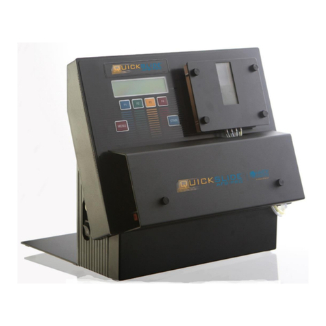
VITAL SCIENTIFIC Vitalab Micro User manual

VITALAB MICRO & MICROLAB 200
VITAL SCIENTIFIC SERVICE MANUAL
VITAL SCIENTIFIC
SERVICE MANUAL

VITALAB MICRO & MICROLAB 200
VITAL SCIENTIFIC SERVICE MANUAL
p/n : 3086-333
Copyright : 1995
Release : January 31st 1995

VITALAB MICRO & MICROLAB 200
VITAL SCIENTIFIC SERVICE MANUAL


VITALAB MICRO & MICROLAB 200
VITAL SCIENTIFIC SERVICE MANUAL i
CONTENTS.
CONTENTS..................................................... i
PREFACE..................................................... iv
ABOUT THE MANUAL. iv
INTRODUCTION. iv
SCOPE AND ORGANIZATION. v
REPAIR POLICY vi
WARRANTY vi
SPARE PARTS vi
TECHNICAL ASSISTANCE vii
SERVICE TRAINING vii
FIELD SERVICE INFORMATION vii
1 GENERAL DESCRIPTION...................................... 1.1
1.1 INTRODUCTION. 1.1
1.2 PHYSICAL DESCRIPTION. 1.1
1.2.1 Introduction. 1.1
1.2.2 Mechanical design. 1.3
1.2.3 Optical design. 1.3
1.2.4 Fluid system description. 1.4
1.3 FUNCTIONAL DESCRIPTION. 1.7
1.3.1 Introduction. 1.7
1.3.2 System Organization and Data Structure. 1.7
1.3.3 Signal Processing. 1.7
1.3.4 Temperature control. 1.9
1.3.5 Test / Diagnostic routines. 1.10
2 THEORY OF OPERATION...................................... 2.1
2.1 INTRODUCTION. 2.1
2.2 PROCESSOR BOARD. 2.1
2.2.1 Microprocessor. 2.1
2.2.2 Memory. 2.1
2.2.3 PIO 2.2
2.2.4 KIO 2.2
2.2.5 Centronics interface. 2.2
2.2.6 RS232C serial interface. 2.3
2.2.7 Programmable input amplifier. 2.3
2.2.8 Vlin / Tlog converter. 2.6
2.2.9 Lamp stabilizer. 2.8
2.2.10 Temperature control. 2.8
2.2.11 System component drivers. 2.12

VITALAB MICRO & MICROLAB 200
VITAL SCIENTIFIC SERVICE MANUALii
2.3 OPTO BOARD. 2.13
2.4 OPTICAL BLOCK. 2.13
2.5 SWITCHED POWER SUPPLY. 2.14
2.5.1 input/output connections. 2.14
2.6 DISPLAY. 2.14
2.7 KEYBOARD and KEYBOARD INTERFACE. 2.15
2.7.1 Principle of scanning. 2.15
2.8 PRINTER. 2.17
3 INSTALLATION AND MAINTENANCE............................. 3.1
3.1 INSTALLATION AND INITIAL CHECKOUT. 3.1
3.2 SERIAL INTERFACE. 3.4
3.2.1 Introduction. 3.4
3.2.2 Serial Format and Baudrate settings. 3.4
3.2.3 Interface Cable Connections. 3.5
3.2.4 Software requirements. 3.6
3.2.4.1 Data format for computer. 3.6
3.2.4.2 Character set. 3.7
3.2.4.3 Output buffer. 3.7
3.3 PREVENTIVE MAINTENANCE. 3.8
3.3.1 Introduction. 3.8
3.3.2 Yearly maintenance. 3.8
3.4 SPECIAL SERVICE TOOLS. 3.9
3.5 MAINTENANCE PROCEDURES. 3.10
3.5.1 Cover cleaning. 3.10
3.5.2 Remove cover. 3.10
3.5.3 Empty fluid system. 3.10
3.5.4 Cleaning of base-plate. 3.10
3.5.5 Fluid system cleaning. 3.10
3.5.6 2-Absorbance test. 3.11
3.5.7 Mounting of the IFL filters. 3.12
3.5.8 Flowcell removal. 3.13
3.5.9 Flowcell assembly / disassembly. 3.13
3.5.10 Lamp replacement. 3.14
3.5.11 Lamp adjustment. 3.15
3.5.12 Valve replacement. 3.15
3.5.13 Bellows replacement. 3.15
3.5.14 Tube replacement. 3.16
3.5.15 Fuse replacement. 3.16
3.6 TEST AND DIAGNOSTIC PROCEDURES. 3.17
3.6.1 Power on check. 3.17
3.6.2 Internal diagnostics. 3.19
3.6.3 Service menu's. 3.19
3.6.4 Energy test. 3.23
3.6.5 Processor board/ powerboard adjustment. 3.23

VITALAB MICRO & MICROLAB 200
VITAL SCIENTIFIC SERVICE MANUAL iii
4 TROUBLESHOOTING.......................................... 4.1
4.1 No sample aspiration. 4.1
4.2 Insufficient sample aspiration. 4.2
4.3 Temperature error message. 4.3
4.4 Sample/water under instrument. 4.3
4.5 ERROR instead of result. 4.3
4.6 Inconsistent measurement results. 4.4
4.6.1 Drop outs. 4.4
4.6.2 Bad reproducibility. 4.5
4.6.3 Results too low. 4.5
4.6.4 Blank error. 4.5
5 EXPLODED VIEWS & DIAGRAMS................................ 5.1
5.1 EXPLODED VIEW of COVER 5.2
5.2 EXPLODED VIEW of BASEPLATE 5.4
5.3 EXPLODED VIEW of OPTICAL BLOCK 5.6
5.4 EXPLODED VIEW of PUMPUNIT and FLOWCELL 5.8
5.5 PROCESSORBOARD 6001-616 5.10
layout of components 5.11
6001-616 1/5 CPU 5.13
6001-616 2/5 KIO, I/O 5.15
6001-616 3/5 Temperature control 5.17
6001-616 4/5 Amplifier, lin/log converter photometric
signal. 5.19
6001-616 5/5 Drivers 5.21
5.6 KEYBOARD CONNECTION BOARD 6001-721 5.23
layout of components 5.23
6001-721 1/1 keyboard connection board 5.25
WIRING VITALAB MICRO 6001-710 1/1 5.27
WIRING MICROLAB-200 6001-950 1/1 5.29
6 SERVICE INFO'S........................................... 6.1

VITALAB MICRO & MICROLAB 200
VITAL SCIENTIFIC SERVICE MANUALiv

VITALAB MICRO & MICROLAB 200 PREFACE
VITAL SCIENTIFIC SERVICE MANUAL v
PREFACE.
ABOUT THE MANUAL.
This manual provides a detailed description, as well as pre-
ventive- and corrective maintenance instructions for the Vita-
lab Micro and the MICROLAB-200 Analyzer.
INTRODUCTION.
The instrument is a universal Photometric Analyzer. The
advanced software gives the instrument an operator interface
which is user oriented and friendly to meet individual
requirements of clinical chemistry laboratory.
40 tests can be defined and programmed by the user, to meet
individual requirements.
The universal curve-fitting program gives automatic result
calculation for "non-linear" tests, such as immuno chemistry,
drug assays, etc..
The unit is completely self contained and only external power
is needed to operate it.
There are two types of parallel thermal printer which can be
delivered. One type is powered by the analyzer and the other by
line voltage.

VITALAB MICRO & MICROLAB 200 PREFACE
VITAL SCIENTIFIC SERVICE MANUALvi
SCOPE AND ORGANIZATION.
This "Service manual" is part of a two volume set. The other
volume "User manual" is supplied with each instrument.
Title P/n
User manual VITALAB MICRO
English, German 3086-147
English 3086-142
German 3086-144
Service manual VITALAB MICRO, English 3086-132
Service manual MICROLAB-200, English 3086-332
User manual MICROLAB 200
English, German, Spanish 3086-347
The "User manual" provides directions for installation and
checkout, and detailed operating instructions. The technical
specifications, as well as a concise maintenance schedule and
some brief troubleshooting information are included.
The "Service manual" has been prepared for service engineers
involved in maintaining and repairing any of the modules of the
analyzer. It contains preventive / corrective maintenance
instructions and trouble shooting.
Chapter 1, "General Description", provides an overall
functional and physical description of the instrument without
describing the electronics and mechanics in detail.
Chapter 2, "Theory of Operation", covers circuit descriptions
concerning processorboard, optical block, switched powersupply,
printer and keyboard interface board.
Chapter 3, "Installation and Maintenance", provides
instructions for installation and maintenance like adjustments
and assembly/disassembly instructions.
Chapter 4, "Troubleshooting", describes the possible relation
between symptoms, causes and actions in case of troubles.

VITALAB MICRO & MICROLAB 200 PREFACE
VITAL SCIENTIFIC SERVICE MANUAL vii
Chapter 5, "Exploded views and Schematics", contains
illustrated mechanical exploded views, PCB schematics and
associated parts-lists for ordering of service parts.
Chapter 6, "Service info's", gives the user of the manual the
possibility to store information concerning modification, the
so called Service info's.

VITALAB MICRO & MICROLAB 200 PREFACE
VITAL SCIENTIFIC SERVICE MANUALviii
REPAIR POLICY
We have implanted a fixed repair price for some parts of the
instrument. These repair prices are a certain percentage of the
Nett ex factory price of that part. The fixed repair prices are
mentioned in the separate Spare Parts Price List.
Vital Scientific will only accept assemblies for repair when
accompanied by a complete filled-out Repair Form with a clear
description of the fault. This will be both for warranty claims
as for normal repairs.
Repair Forms will be supplied by Vital Scientific, free of
charge.
WARRANTY
Refer to the section "General Conditions of Sale" in the Price
list for the warranty policy.
Unless specified otherwise a warranty period of three Months
will be applicable for repaired parts. Except for the warranty
period, the remaining warranty conditions are the same as those
described in the Price list.
SPARE PARTS
Distributors are expected to stock sufficient spare parts to be
able to provide first line service support. The distributors
should be aware of the fact that although Vital Scientific
strives for off-the-self availability of spare parts, depending
upon the demand and the production schedules, lead times may
exist and therefore certain parts may not always be instantly
available. A list with Recommended Spare- parts can be found in
the Spare Parts Price List.

VITALAB MICRO & MICROLAB 200 PREFACE
VITAL SCIENTIFIC SERVICE MANUAL ix
TECHNICAL ASSISTANCE
Should you encounter a problem which requires technical
assistance, you may call, fax or telex the Service Department
of Vital Scientific. Please be prepared to give a clear and
complete description of the problem. Also be prepared to give
an answer to the following questions:
- type of instrument
- serial number
- software version (when applicable)
- revision level (in case of a PCB)
SERVICE TRAINING
Service training courses are organized on a regular base and
you will be informed on fore-hand. In principle courses will be
held at Vital Scientific, but in consultation it is possible to
organize a course at the customers site.
Participants are expected to have knowledge of:
- modern analog/digital electronics
- microprocessor techniques
- basic photometric techniques
- the English language
For information about service training, please contact the
Service Department of Vital Scientific.
FIELD SERVICE INFORMATION
In November 1991 we have introduced a Field Service Information
system. The purpose of such a system is to provide detailed
information on the frequency and nature of failures that occur
during field use. This information enables us to take
corrective actions and to improve on the design and
manufacturing methods.
For this purpose we have designed two different forms:
- Installation report
- Malfunctioning report
The Installation report should be filled-out when the
instrument is installed at the customers site. The

VITALAB MICRO & MICROLAB 200 PREFACE
VITAL SCIENTIFIC SERVICE MANUALx
malfunctioning report should be filled-out each time when a
service is performed on the instrument.
The installation form as well as a number of malfunctioning
forms are included in the packing of the instrument. We request
you to return the filled-out forms to us on a regular base (for
example once a month) by mail or fax, whatever is convenient.

VITALAB MICRO & MICROLAB 200 PREFACE
VITAL SCIENTIFIC SERVICE MANUAL xi


VITALAB MICRO & MICROLAB 200 GENERAL DESCRIPTION
VITAL SCIENTIFIC SERVICE MANUAL 1.1
1 GENERAL DESCRIPTION.
1.1 INTRODUCTION.
The instrument is a small stand-alone photometer for the normal
routine tests in a laboratory. It is designed in such a way
that operating and servicing takes a minimum of time. The light
weight and compact design, the flexibility, easy of operation
and reliability are the prime features.
The instrument is microprocessor controlled, designed for
photometric determinations of Enzymes and Substrates by
Kinetic, Two-point, and Endpoint calculations. Reagent blank
corrections, serum blank corrections and calibration, as well
as a linearity check in the Kinetic mode are standard features.
For the above mentioned determinations it is also possible to
calibrate on a non-linear curve.
1.2 PHYSICAL DESCRIPTION.
1.2.1 Introduction.
The analyzer is a compact instrument of modern and straight
forward design. This design has been engineered with a precise
simplicity, which will assure a high level of reliability.
Ease of maintenance and trouble-shooting has been taken into
consideration during the design phase, with the result that all
components (other than specific mechanical components) have
been selected if possible from manufacturer's 'off-the shelf'
stock. Should a component fail, it may be easily replaced by
Vital.
The units have been designed for plug-in replacement of
circuit boards and major mechanical assemblies, which permits
on-site repair thus ensuring an absolute minimum of equipment
down-time.
In order to support the service technician, comprehensive test,
diagnostic and alignment procedures have been included in the
software.
Perhaps the most significant feature of the instrument is the
easy of operation and still allows a wide range of reagents and

VITALAB MICRO & MICROLAB 200 GENERAL DESCRIPTION
VITAL SCIENTIFIC SERVICE MANUAL1.2
methods to be used.
In figure 1.1. a functional diagram given of the complete
instrument.
Figure 1.1 Functional diagram.

VITALAB MICRO & MICROLAB 200 GENERAL DESCRIPTION
VITAL SCIENTIFIC SERVICE MANUAL 1.3
1.2.2 Mechanical design.
The Analyzer consists of two major assemblies:
- The baseplate assembly, containing:
- Optical system
- Fluid system
- Power supply
- Processor board
- The poly-urethane cover assembly, containing:
- Foil keyboard
- LCD display
* Note that the inside of the cover is coated with a special
conductive paint, which is connected to system ground.
The instrument is controlled via the 52-key foil keyboard.
Other operators controls are the 16 lines by 20 characters LCD
display, alphanumeric printer, prime LED, prime switch, display
contrast potmeter and the power switch (double pole) at the
rear of the instrument.
1.2.3 Optical design.
Referring to figure 1.2, illustrating the optical system of the
analyzer, the light source consists of a special, long-life
12V/20W quartz iodine lamp (typical: 2000 hour life time),
while the detector is made up of a UV-enhanced silicon
photocell.

VITALAB MICRO & MICROLAB 200 GENERAL DESCRIPTION
VITAL SCIENTIFIC SERVICE MANUAL1.4
The optical system has been kept as simple as possible.
The filament of the lamp is projected in the lens in front of
the flowcell, whilst the diaphragm is projected just after the
flowcell, creating a parallel light beam in the flowcell.
Monochromatic light is achieved by using single IFL filters
(interference Line). The filters are mounted in a stepper motor
driven, 8-position filter wheel.
Depending on the test carried out on the moment, the
microprocessor will automatically (under program control) set
the filterwheel to the correct position.
For the high wavelength range a filter with a low transmittance
is used to level difference in energy at the low and high ends
of the spectral range. This will be necessary, because the
spectral emission of the quartz iodine lamp and the spectral
response of the detector are both much higher in the visible
and near infra-red range than in the near ultra-violet range.
For optimal alignment and light intensity the lamp can be
adjusted in the horizontal and the vertical position. The third
screw is used to lock the lamp into the adjusted position.
This manual suits for next models
1
Table of contents
Popular Laboratory Equipment manuals by other brands

Thermo Scientific
Thermo Scientific S1 Instructions for use

NUVE
NUVE NF 048 user manual

Woson Medical Instrument Co., Ltd
Woson Medical Instrument Co., Ltd TANZO Classic Operation manual

Thermo Scientific
Thermo Scientific VARIOMAG MINI 07 operating manual

Codex
Codex BioXp 3200 Uncrating and crating

TESTO
TESTO 865s instruction manual