VITALI T5 Evo User manual
DENTAL UNITS & CHAIRS
Technical
Manual
EN
T5 Evo Dental Units T5 Evo / V8e

1
2
3
4
5
6
7
8
9
10
Foreword
This technical manual, which is provided to VITALI distributors, in-
cludes the information necessary for the execution of operations
which can be carried out by appropriately trained and authorized
technical staff.
The document is divided into sections identified by a number and
by a colour. Each section contains several explanatory chapters of
the issue being discussed.
The manual is structured in such a way as to allow for the inclusion
of additional sections/chapters.
The first letter used in the identification code of connectors, fuses
and LEDs present on the electronic cards indicates their position:
P = chair power card and motherboard, R = cuspidor card, S =
instrument preselection card (e.g., SC1 connector, SF2 fuse, etc.).
Operator’s manuals
• WARRANTY
• SYMBOLS USED
• TECHNICAL DATA
• INSTALLATION NOTES
• SERIAL NUMBER AND LABELS LOCATION
• ROUTINE MAINTENANCE
Installation manuals
• INSTALLATION MANUAL
• 1:1 TEMPLATE INSTALLATION
Hydro-pneumatic circuit
Chair’s electric unit
• LOCATION
• ELECTRONICS CARDS
• ELECTRIC DIAGRAM
Water unit
• LOCATION
• ELECTRONICS CARDS
• ELECTRIC DIAGRAM
Operator’s table
• LOCATION
• ELECTRONICS CARDS
• ELECTRIC DIAGRAM
• SETTINGS
• DIAGNOSTICS AND ALARMS
Assistant’s console
• LOCATION
• ELECTRONICS CARDS
• ELECTRIC DIAGRAM
Foot controls
• LOCATION
• ELECTRONICS CARDS
• ELECTRIC DIAGRAM
Maintenance:
• ROUTINE MAINTENANCE
• SPECIAL MAINTENANCE
• REPAIRING AND/OR REPLACEMENT
FORM
Assembly diagrams for accessories
TECHNICAL MANUAL
DENTAL UNIT Mod. T5 Evo / V8e
(COD. 66000024-EN - UPG. 27/05/2013)
Whenever assistance/maintenance work involves the
equipment, the MAINTENANCE CARD contained in
the Operator’s Manual relating to the maintained device
must be filled out.
WARNING: DO NOT FILL OUT THE MAINTENANCE
CARD CONTAINED IN THE ATTACHED OPERATOR’S
MANUAL.
WARNING: after switching off the equipment by pressing
the main switch, ,power may still be supplied to some
parts of the equipment. Therefore, in case of access to
parts under tension, it is always necessary to disconnect
the supply plug or to act on the general disconnecting
switch of the electric plant.
3.0 1/2
Technical manual ›
T5 EVO/V8e COD. 66000024-EN - 12/03/2012
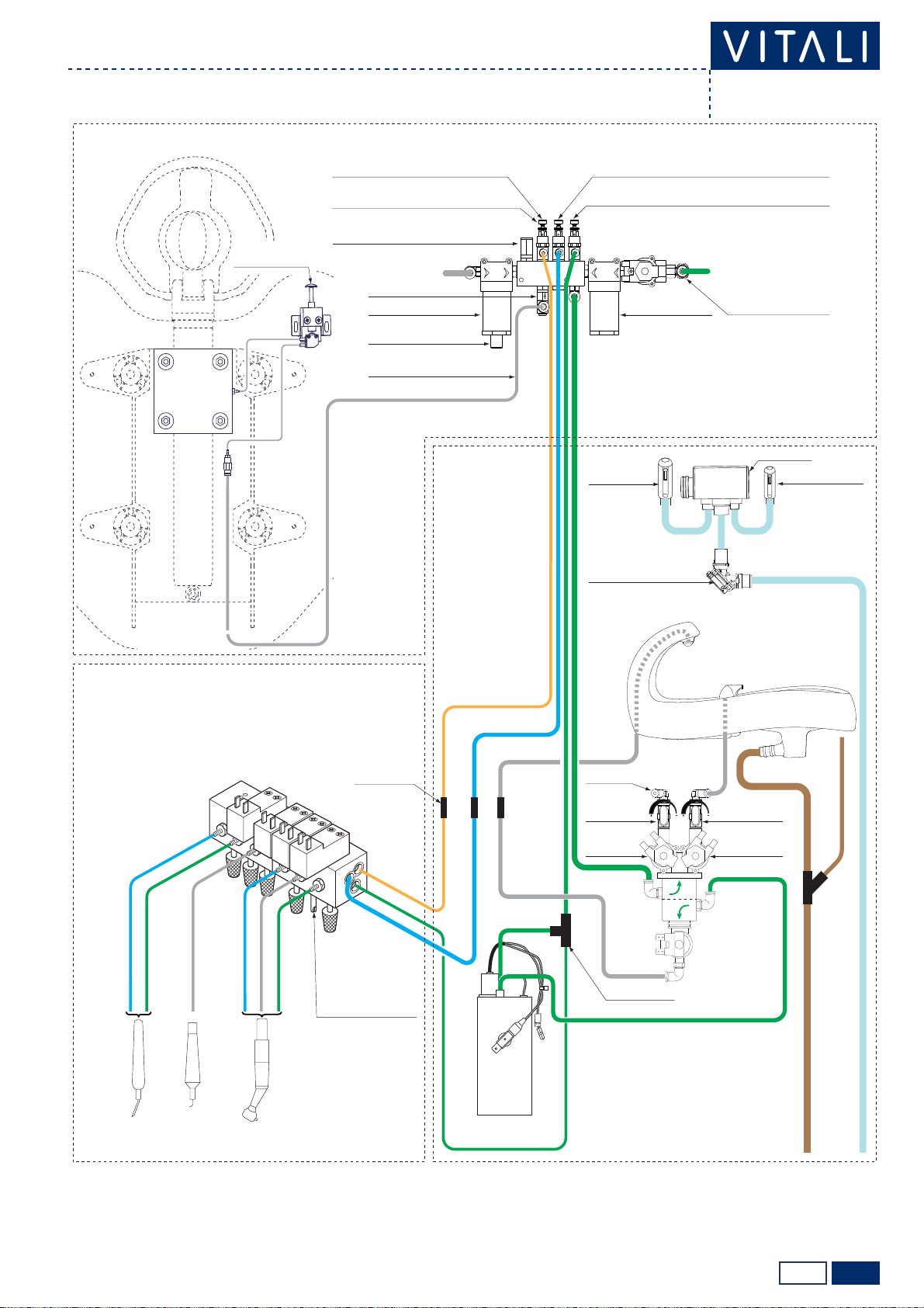
Hydro-pneumatic diagram
WARNING:
(*) the pressure adjuster must be calibrated according to the instrument that needs The highest pressure.the flow adjusters must be calibrated to
ensure the proper working pressure to instruments with a lower pressure/consumption of air.
(**) if there is the water boiler, the flow of water to the tumbler cannot be changed
TUMBLER WATER
SOLENOID VALVE
NOT
CONNECTED
AIR
INTAKE
DRAINAGE
SURGICAL SUCTION (WET SYSTEM)
Ø4mm YELLOW
Ø4mm YELLOW
Ø4mm RED
“T” QUICK JOINT
TUMBLER
WATER BOILER
(OPTIONAL)
FLOW REGULATOR
ADJUSTED FOR THE AIR
DRIVING OF THE TURBINE
OR THE AIR COOLINGFOR
THE MICROMOTOR (*)
Ø4mm WHITE
Ø3mm TRASPARENT
Ø6mm BLUE
Ø6mm BLUE
Ø6mm WHITE
Ø6mm WHITE
Ø8mm GREEN
Ø6mm GREEN
Ø6mm GREEN
Ø6mm GREEN
Ø4mm GREEN
Ø6mm WHITE
TUMBLER WATER
SOLENOID VALVE
(OPTIONAL) (**)
SPITOON WATER
SOLENOID VALVE
SPITOON WATER
FLOW ADJUSTER
TUMBLER WATER
FLOW ADJUSTER
MAIN WATER INLET
(Ø 8 mm HOSE)
MAIN AIR INLET
(Ø 8 mm HOSE)
TURBINE or
MICROMOTOR
SYRINGE SCALER
QUICK JOINT
HEADRESTAIR (INLET PRESSURE)
INSTRUMENTS WATER (2.2±0.2 bar)
CHIP-BLOWER AIR, INSTRUMENT SPRAY AIR,
SYRINGE AIR (3.6±0.2 bar)
DRIVING AIR FOR TURBINE, COOLING AIR
FOR MICROMOTOR (ACCORDING TO THE TYPE OF
INSTRUMENT DEFAULT 2.2±0.2 bar – EXHAUST <0.4 bar) (*)
PRESSURE ADJUSTER
MAIN WATER PRE-FILTER
COLLECTOR
PRESSURE SAFETY VALVE (10 bar)
MAIN AIR FILTER
ONE-WAY VALVE
SURGICAL
SUCTION
TERMINAL Ø17
ELECTROPNEUMATIC
VALVE (OPTIONAL)
WATER VESSEL
EMPTYING VALVE
MAIN WATER FILTER
T5 EVO CHAIR
T5 EVO WATER UNIT
T5 EVO INSTRUMENT TABLE
SURGICAL
SUCTION
TERMINAL Ø11
GREEN
GREEN
TRASPARENT
TRASPARENT
BLUE
BLUE
HEADREST BRAKE
PUSHBUTTON

2/23.0
Technical manual ›
T5 EVO/V8e
COD. 66000024-EN - 12/03/2012
WARNING:
(*) the pressure adjuster must be calibrated according to the instrument that needs The highest pressure.the flow adjusters must be calibrated to
ensure the proper working pressure to instruments with a lower pressure/consumption of air.
(**) if there is the water boiler, the flow of water to the tumbler cannot be changed
TUMBLER WATER
SOLENOID VALVE
NOT
CONNECTED
AIR
INTAKE
DRAINAGE
SURGICAL SUCTION (WET SYSTEM)
Ø4mm YELLOW
Ø4mm YELLOW
Ø4mm RED
“T” QUICK JOINT
TUMBLER
WATER BOILER
(OPTIONAL)
FLOW REGULATOR
ADJUSTED FOR THE AIR
DRIVING OF THE TURBINE
OR THE AIR COOLINGFOR
THE MICROMOTOR (*)
Ø4mm WHITE
Ø3mm TRASPARENT
Ø6mm BLUE
Ø6mm BLUE
TUMBLER WATER
SOLENOID VALVE
(OPTIONAL) (**)
SPITOON WATER
SOLENOID VALVE
SPITOON WATER
FLOW ADJUSTER
TUMBLER WATER
FLOW ADJUSTER
MAIN WATER INLET
(Ø 8 mm HOSE)
MAIN AIR INLET
(Ø 8 mm HOSE)
TURBINE or
MICROMOTOR
SYRINGE SCALER
QUICK JOINT
TO THE ARM BRAKE
RELEASE AIR
HEADRESTAIR (INLET PRESSURE)
ARM BRAKE (INLET PRESSURE)
INSTRUMENTS WATER (2.2±0.2 bar)
CHIP-BLOWER AIR, INSTRUMENT SPRAYAIR,
SYRINGE AIR (3.6±0.2 bar)
DRIVING AIR FOR TURBINE, COOLING AIR
FOR MICROMOTOR (ACCORDING TO THE TYPE OF
INSTRUMENT DEFAULT 2.2±0.2 bar – EXHAUST <0.4 bar) (*)
PRESSURE ADJUSTER
MAIN WATER PRE-FILTER
COLLECTOR
PRESSURE SAFETY VALVE (10 bar)
MAIN AIR FILTER
ONE-WAY VALVE
SURGICAL
SUCTION
TERMINAL Ø17
ELECTROPNEUMATIC
VALVE (OPTIONAL)
WATER VESSEL
EMPTYING VALVE
MAIN WATER FILTER
V8e CHAIR
V8e WATER
UNIT
V8e INSTRUMENT TABLE
HEADREST BRAKE
PUSHBUTTON
SURGICAL
SUCTION
TERMINAL Ø11
GREEN
GREEN
TRASPARENT
TRASPARENT
BLUE
BLUE
Ø4mm GREEN
Ø6mm GREEN
Ø6mm GREEN
Ø6mm WHITE
Ø6mm WHITE
Ø6mm GREEN
Ø8mm GREEN

4.0 1/1
PC1
PC2
PC4
i
i
PF1 PF2
59400048
59400049
Technical manual ›
T5 EVO/V8e COD. 66000024-EN - 01/01/2012
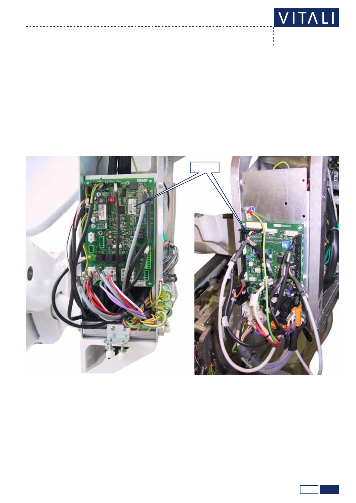
Location
Chair’s electrict unit
To replace fuses PF1 and PF2, draw out
the fuse-holder tray by using a athead
screwdriver in the points shown with the
arrows (see image on the side).
PC2, PC3: auxiliary connections whose use is meant only for
the connection of additional devices approved by VITALI.
230VAC 50-60 Hz outlet present also
with disconnected network switch.
230VAC 50-60 Hz outlet not present
also with disconnected network
switch.
To have access to the electric unit, take away the transparent guard as indicated in the T5 EVO Installation
Manual (cap. ELECTRIC, WATER AND PNEUMATIC CONNECTIONS).

4.1 1/2
PCB COD. 59400048
Technical manual ›
T5 EVO/V8e COD. 66000024-EN - 01/05/2011
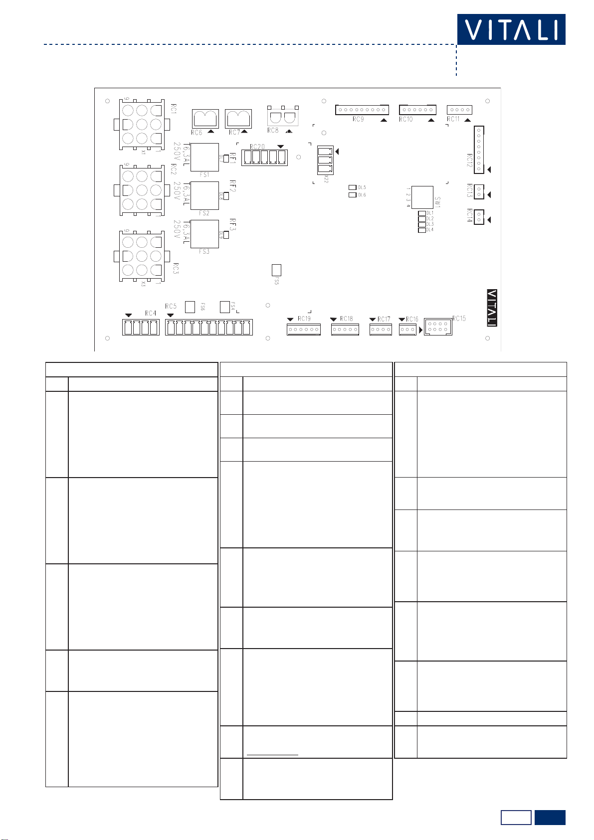
Chair card ref. 59400048
Chair electric unit
CONNECTORS
N° DESCRIPTION
PC0 Connection for logic unit cod.59400049
PC1 1 - IN 230 Vac
2 - IN 230 Vac
3 - Earth
PC2 1 - 230 Vac (AUX - no interrupted by main switch)
2 - 230 Vac (AUX - no interrupted by main switch)
3 - Earth
PC3
1 - IN 230 Vac (main switch)
2 - IN 230 Vac (main switch)
3 - OUT 230 Vac (main switch)
4 - OUT 230 Vac (main switch)
PC4 1 - 230 Vac (AUX)
2 - 230 Vac (AUX)
3 - Earth
PC5 1 - 230 Vac (AUX)
2 - 230 Vac (AUX)
PC6 1 - 230 Vac (1st TRS)
2 - 230 Vac (1st TRS)
PC7 1 - 230 Vac (UV-Osmo)
2 - 230 Vac (UV-Osmo)
PC8
1 - +25 Vdc (AUX)
2 - CAN H (serial communication)
3 - CANL (serial communication)
4 - Ground
5 - 24Vac (AUX)
6 - 24Vac (AUX)
PC9
1 - Normal Open contact assistant call
2 - N.O. contact a.c. (24Vac/dc, 3A, resistive load)
3 - Normal Open contact suction motor
4 - N.O. contact s.m. (24Vac/dc, 3A, resistive load)
PC10
1 - 24 Vac (instrument selection card)
2 - 21 Vac (instrument selection card)
3 - 21 Vac (instrument selection card)
4 - 24 Vac (instrument selection card)
5 - CAN H (serial comunication instr. selec. card)
6 - CAN L (serial comunication instr. selec. card)
7 - +34 Vdc (instrument selection card)
8 - +25 Vdc (instrument selection card)
9 - Ground
CONNECTORS
N° DESCRIPTION
PC11
1 - 24 Vac (instrument selection card Clip6)
2 - 21 Vac (instrument selection card Clip6)
3 - 21 Vac (instrument selection card Clip6)
4 - 24 Vac (instrument selection card Clip6)
5 - CAN H (serial comm. for instr. sel. card Clip6)
6 - CAN L (serial comm. for instr. sel. card Clip6)
7 - +34 Vdc (instrument selection card Clip6)
8 - +25 Vdc (instrument selection card Clip6)
9 - Ground
PC12
1 - 25 Vac (2nd TRS)
2 - 21 Vac (2nd TRS)
3 - 24 Vac (2nd TRS)
4 - 25 Vac (2nd TRS)
5 - 21 Vac (2nd TRS)
6 - 24 Vac (2nd TRS)
PC13
1 - +25 Vdc
2 - CAN H (serial communication VDS keyboard)
3 - CAN L (serial communication VDS keyboard)
4 - Ground
PC14
1 - +25 Vdc
2 - CAN H (serial communication foot control)
3 - CAN L (serial communication foot control)
4 - Ground
PC15
1 - 34 Vdc (chair motor power supply) (+/-)
2 - 34 Vdc (chair motor power supply) (-/+)
3 - 34 Vdc (backrest motor power supply) (+/-)
4 - 34 Vdc (backrest motor power supply) (-/+)
PC16
1 - + (10 kΩ chair potentiometer) (*)
2 - Cursor (10 kΩ chair potentiometer)
3 - - (10 kΩ chair potentiometer)
4 - Chair descent limit microswitch
5 - Common micro. descent and chair safety
6 - Chair safety microswitch
7 - Chair rise limit microswitch
8 - Chair rise limit microswitch
CONNECTORS
N° DESCRIPTION
PC17
1 - + (backrest potentiometer 10 KΩ) (**)
2 - Cursor (backrest potentiometer 10 KΩ)
3 - - (backrest potentiometer 10 KΩ)
4 - Backrest descent limit microswitch
5 - Common micro. descent and backrest safety
6 - Backrest rise limit microswitch
7 - Common micro. rise and backrest safety
8 - N.C.
PC18
1 - Emergency stop button (N.O.)
2 - Emergency stop button (N.O.)
3 - Red LED (maintenance or emergency)
4 - Green LED (ordinary operation)
5 - Common LED
6 - N.C.
PC19
1 - + Solenoid valve N.A. 1 (instruments water)
(VDS)
2 - - Solenoid valve N.C. 1 (VDS)
3 - + Sol. valve N.C. 2 (Multiclean drawing) (VDS)
4 - - Solenoid valve N.C. 2 (VDS)
5 - + Sol. v. N.C. 3 (air for Multiclean pressurized
bottle) (VDS)
6 - - Solenoid valve N.C. 3 (VDS)
7 - + Sol. v. N.C. 4 (sterile liquid) (VDS)
8 - - Solenoid valve N.C. 4 (VDS)
9 - + Sol. v. N.C. 5 (sterile liquid air) (VDS)
10 - - Solenoid valve N.C. 5 (VDS)
PC20 1 - + Main water inlet solenoid valve
2 - - Main water inlet solenoid valve
PC21
1 - Common pressure switch (+25Vdc)
2 - Water pressure switch (for VDS only)
3 - Air pressure switch (for VDS only)
4 - Ground (not used)
PC22 1 - UV lamp alarm (for UV-Osmo or VDS only)
2 - UV lamp alarm (for UV-Osmo or VDS only)
PC23 1 - Earth
(*) chair rise = 10 KΩ between 2 and 3, chair descent = 10 KΩ between 1 and 2.
(**) backrest rise = 10 KΩ between 2 and 3, backrest descent= 10 KΩ between 1 and 2.

2/24.1
Technical manual ›
T5 EVO/V8e
COD. 66000024-EN - 01/05/2011
LED
N° INDICATION
DL1 Presence of 12 Vcc voltage
DL2 Presence of 25 Vcc voltage
DL3 Integrity fuse PF3
DL4 Integrity fuse PF4
DL5 Integrity fuse PF5
DL6 Integrity fuse PF6
DL7 Integrity fuse PF7
DL8 Nurse call activation
DL9 Surgical aspirator activation
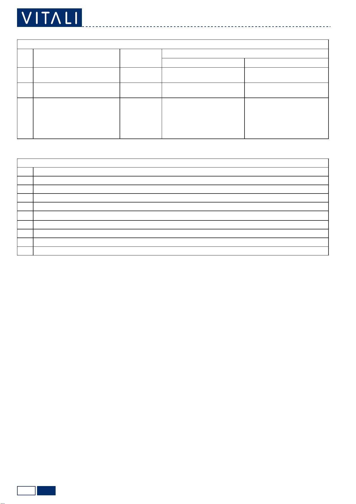
FUSES
N° PROTECTED PARTS VALUE AND
TYPE
ANOMALIES THAT CAN BE DETECTED AFTER INTERRUPTION
FUNCTIONS LIGHTS
PF1 230Vac line T. 4AL (5x20)
DELAYED
Nothing works. Main switch off.
PF2 230Vac line T. 4AL (5x20)
DELAYED
Nothing works. Main switch off.
PF3 Auxiliary 24 Vac line (PC8) T. 6.3AL (5x20)
DELAYED
The relay for suction motor con-
trol (optional) and any users con-
nected to PC8 are not working.
DL3 off.
PF4 24 Vac line T. 8AL (5x20)
DELAYED
The users fed in alternating
mode are not working (amalgam
separators, 6F syringe, polyme-
riser, etc.).
DL4 off.
PF5 21 Vac line T. 6.3A (5x20)
DELAYED
The operating light is not wor-
king. DL5 off.
PF6 Feeder power supply 34 Vcc T. 8A (5x20)
DELAYED Nothing works. DL6, DL7, emergency button ring
off.
PF7 34 Vac line T. 6.3A (5x20)
DELAYED
The driving air and instrument
cooling solenoid valves are not
working.
The micromotor and the turbine
are not running.
DL6, DL7, emergency button ring
off.
4.2 1/3
O
N
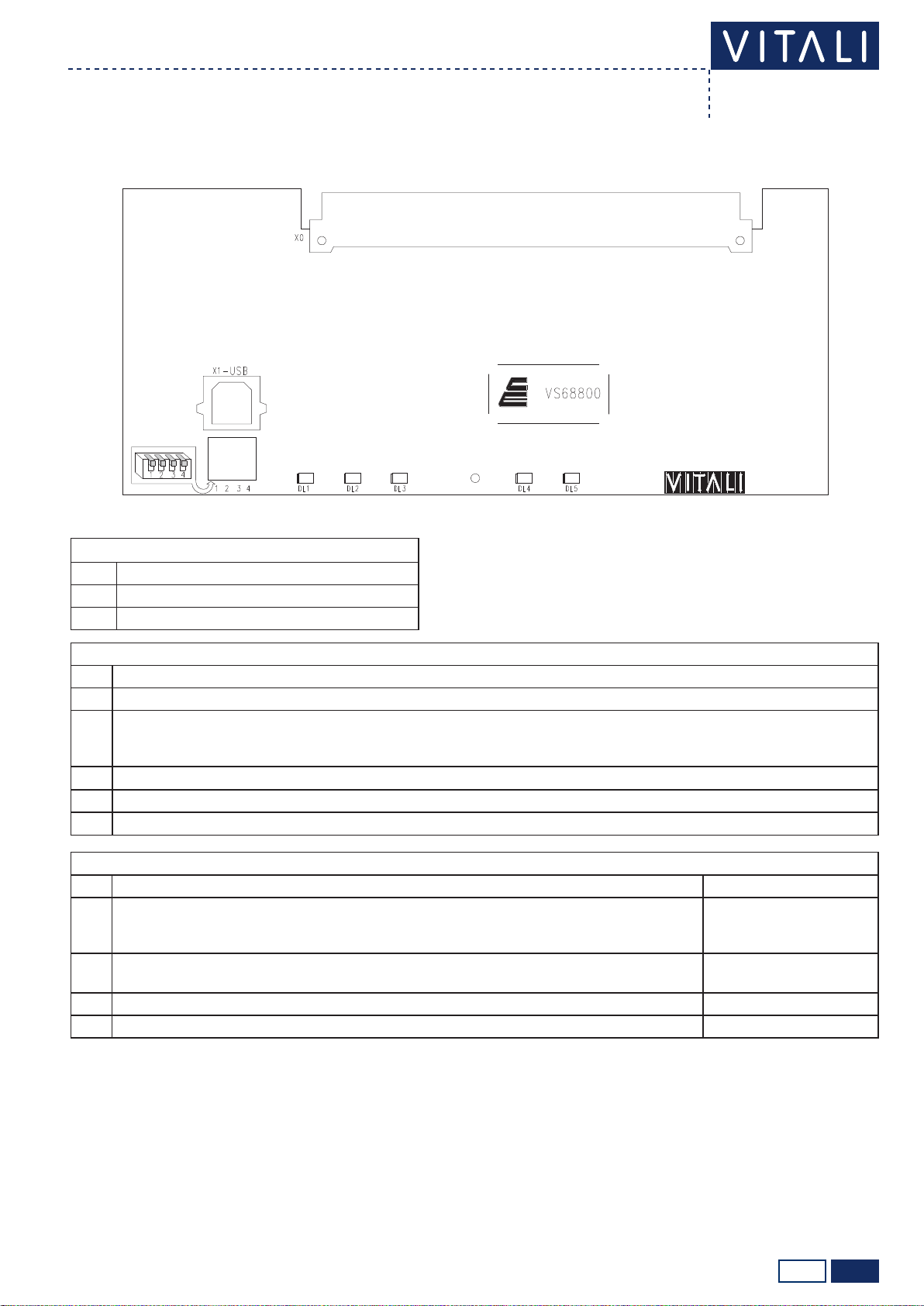
PCB COD. 59400049
Technical manual ›
T5 EVO/V8e COD. 66000024-EN - 01/05/2011
Chair card ref. 59400049
Chair’s electric unit
CONNECTORS
N° DESCRIPTION
X0 BUS FOR CONNECTION TO THE CHAIR CARD CODE 59400048
X1-USB USB SWITCH FOR CONNECTION TO PC
LED
N° INDICATION
DL1 Active USB connection.
DL2
If all the dip-switches of SW1 are turned off (OFF), it indicates the proper functioning of the serial connection. With the dip-
switch 1 of SW1 on (ON), the LED is dedicated to the calibration of potentiometers (see below, description of Dip-Switch
SW1).
DL3 Reserved.
DL4 Chair movement in progress.
DL5 Presence of card power supply.
DIP-SWITCH SW1
N° ON OFF
1 Adjustment of limit switch and potentiometers (see procedures “Adjusting limit switch and
potentiometer for T5 Evo chair rise” and “Adjusting limit switch and potentiometer for T5 Evo
backrest”).
Standard operation.
2 Transfer of rmware to peripheral devices (see under “Software update”) and visualization/
reset of maintenance timer (see under “Adjusting the maintenance timer”).
Standard operation.
3 Not used. Not used.
4 USB connection (see under procedure “Software update” ). Standard operation.

2/34.2
Technical manual ›
T5 EVO/V8e
COD. 66000024-EN - 01/05/2011
FIRMWARE UPDATE
You can update the rmwares of the cards of the chair (code 59400049), cuspidor (code 59400056)
or instrument preselection (code 59400052), by following the procedure described below.
Required components: personal computer with Microsoft Windows XP® (or latest) operating sys-
tem, A/B-type USB cable (male/male).
Procedure:
1. turn on the PC that contains the les of updated rmwares;
2. turn off the main switch of the equipment;
3. if you wish (this is not essential), you can remove the chair card from its housing (N.B: do not
remove other cards);
4. put the switch 4 of SW1 of the chair card on ON;
5. connect the type-B USB plug to the X1-USB connector;
6. if the chair card is in its housing, turn on the main switch of the equipment;
7. connect the type-A USB cable to the PC;
8. in “My Computer”, go to “VITALI_Disk” to display the les on the chair card:
DESCRIPTION FILE NAME
(FIRMWARE)
DATE OF LAST
CHANGE (REVISION) (*)
Firmware for chair card cod. 59400049 SP33001000V0 Chair 1.cry 08/09/2011 14.00
Firmware for cuspidor card cod. 59400056 SP33006000v0 Riuni 1.cry 08/06/2011 14.00
Firmware for 1st instrument preselection card
cod. 59400052 present in instrument table
SP33009000v0 Selec 1.cry 05/05/2011 12.00
Firmware for 2nd instrument preselection
card cod. 59400052 if present in water unit.
SP33009000v0 Selec 2.cry 05/05/2011 12.00
(*) non-real data, example of date/hour format.
9. drag&drop or cut&paste the new rmware into the “VITALI_Disk” (the le of the new rmware
may have different names, this is irrelevant for updating purposes);
10. carry out the “Safe Hardware Removal” and disconnect the USB cable from the PC when the
system so allows;
11. if necessary, update the other cards, repeat steps 7 to 10 for each new rmware you want to
load.
12. if the chair card is in its housing, turn off the main switch of the equipment;
13. place the switch 4 of SW1 on OFF;
14. put the chair card back into its housing (if necessary);
15. wait for about 10 seconds and turn on the main switch of the equipment;
16. the chair card has been updated;
17. if the rmwares of other cards have been loaded on the chair card, you need to follow the proce-
dure “Uploading rmwares to peripheral devices” to complete the update process.
N.B: the data on the settings of the equipment is in the chair motherboard; however, the updating of
the rmware of this card does not alter stored data.

3/34.2
Technical manual ›
T5 EVO/V8e COD. 66000024-EN - 01/05/2011
UPLOADING FIRMWARES TO PERIPHERAL DEVICES
This procedure is required to transfer updated rmwares from the chair card to cuspidor/instrument
preselection cards.
Procedure:
1. put the dip-switch 2 of SW1 on ON;
2. the ignition of the LEDs of storable positions identify which peripheral devices are connected;
more specically:
= card cod. 59400056 (water unit)
= card cod. 59400052 (1° instrument selection card present in the instrument table)
= card cod. 59400052 (2° instrument selection card, if present in the water unit)
3. keep the key pressed and, without releasing it, press the key that identies the peripheral
device that you want to update for 5 uninterrupted seconds (e.g. + to update the instru-
ment table selection card);
4. the corresponding LED (1, 2 or 3) starts to ash, indicating that the rmware transfer is under-
way;
5. 5. release both keys, wait for the LED to light up and stop ashing, and for a long conrmation
beep;
6. 6. if required, repeat steps 3 to 5 for the other cards that require updating;
7. 7. put the dip-switch 2 of SW1 on OFF;
8. 8. turn the equipment off and then on again;
9. 9. wait for about 10 seconds for the system to overwrite the old rmware.
N.B. if you upload the rmware of the card code 59400056, the restarting of the equipment will be
accompanied by an intermittent sound. The tonality of the last sound of the series indicates whether
or not overwriting has been effective (low/deep sound = failure).
ADJUSTING THE MAINTENANCE TIMER
After about 1,000 hours of operation, the functioningindicator starts ashing for about 1 minute
when the equipment is started (see chapter 9.0).
To change the number of hours counted:
10. Put the dip-switch 2 of SW1 on ON .
11. The LEDs from 1 to 10 of the unit’s keyboard display the remaining time.
(all the LEDs ≈ 1,000 hours, e.g. 1 2 3 4 5 6 7 8 9 10 ≈ 300 hours).
The gure is viewable even in diagnostic mode (see chapter 6.6: Group 0.9).
12. Press and, without releasing it, to set the timer at 1,000 hours or press and, without
releasing it, to set the timer at 0 hours. Wait for the acoustic signal and release both keys.
13. Put the dip-switch 2 of SW1 on OFF.
WARNING: the dip-switch 2 of SW1 can also be used to update the rmwares of peripheral devices
(see chapter UPLOADING FIRMWARES TO PERIPHERAL DEVICES).
N.B: if the chair motherboard is replaced, it is necessary to repeat every customization previ-
ously made to the equipment (see chapter 6.7).

4.3 1/1
Technical manual ›
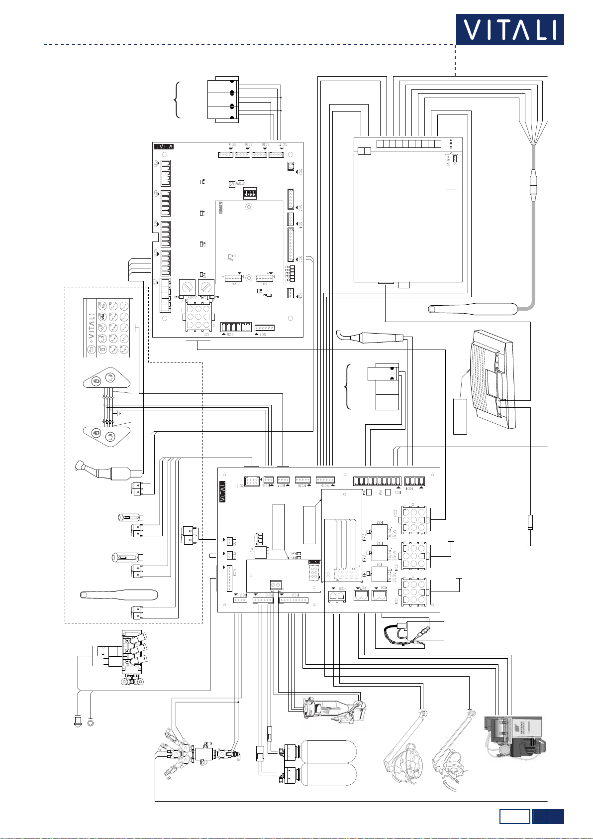
T5 EVO/V8e COD. 66000024-EN - 12/03/2012
Electric diagram
Chair electric unit
PCB COD. 59400048
PCB
COD. 59400050
PCB COD. 59400051
MOTOR 24VCC LA31
BACKREST MOVEMENTS
MOTOR 24VCC LA34
CHAIR MOVEMENTS
LINE
230 VAC 50/60 HZ
PANTOGRAPH COVER SAFETYCHAIR COVER SAFETY
CHAIR
POSITION
TRANSDUCER
CHAIR
DESCENT
LIMIT SWITCH
CHAIR RISE
LIMIT SWITCH
BACKREST
POSTION
TRANSDUCER
EMERGENCY
STOP BUTTON
FUNCTIONING
INDICATOR
WATER GENERAL
SOLENOID VALVE
BIPOLAR
LUMINOUS
MAIN SWITCH
230VAC
50/60Hz
24VAC
50/60Hz
24VAC
50/60Hz
SUCTION
CONTROL
RELAY
UV-OSMO LAMP
VITALI DISINFECTION SYSTEM (OPTIONAL)
TO LINE 230 VAC
50/60 HZ
FOOT CONTROL
PUSH BUTTON
FOOT CONTROL
BACKREST
COVER SAFETY
CHAIR DESCENT
LIMIT SWITCH
BACKREST RISE
LIMIT SWITCH
TO RC1 PCB COD. 59400056
VDS KEYBOARD
VDS SOLENOID VALVES GROUP
TO THE MONITOR
MONITOR
FEEDER
UV-OSMO POWER
FEEDER
TRANSFORMER
V
V I T L I
V
D
S
PCB COD. 59400055
PCB OD 5940 055
PRESSURE SWITCHES
5.0 1/1
59400056
T5 EVO V8e
Technical manual ›
T5 EVO/V8e COD. 66000024-EN - 01/01/2012
Location
Water unit
To have access to the cuspidor column, remove the covers as indicated in the T5 Evo or V8e Installation Manual.
5.1 1/2
PCB COD. 59400056
Technical manual ›
T5 EVO/V8e COD. 66000024-EN - 12/03/2012
Water unit card ref. 59400048
Water unit
CONNECTORS
N° DESCRIPTION
RC1
1 - IN 24 Vac
2 - IN 21 Vac (phase)
3 - IN 21 Vac
4 - IN 24 Vac (phase)
5 - CAN H (SERIAL COMMUNICATION)
6 - CAN L (SERIAL COMMUNICATION)
7 - IN + 34 Vdc
8 - IN +25 Vdc
9 - Ground
RC2
1 - 24 Vac
2 - 21 Vac (phase)
3 - 21 Vac
4 - 24 Vac (phase)
5 - CAN H (SERIAL COMMUNICATION)
6 - CAN L (SERIAL COMMUNICATION)
7 - + 34 Vdc
8 - +25 Vdc
9 - Ground
RC3
1 - 24 Vac
2 - 21 Vac (phase)
3 - 21 Vac
4 - 24 Vac (phase)
5 - CAN H (SERIAL COMMUNICATION)
6 - CAN L (SERIAL COMMUNICATION)
7 - + 34 Vdc
8 - +25 Vdc
9 - Ground
RC4
1 - AUX 24 Vac
2 - AUX 24 Vac (phase)
3 - 24 Vac phase
4 - 24 Vac (phase) Curing light
RC5
1 - Ground
2 - +25 Vdc
3 - + 34 Vdc
4 - Reserved
5 - Reserved
6 - Reserved
7 - + 24Vcc instrument spray water sol. valve
8- Ground instrument spray water sol. valve
9 - +24 Vcc instrument spray air sol. valve
10 - Ground instrument spray air sol. valve
CONNECTORS
N° DESCRIPTION
RC6 1 - 24 Vac Glass water heater
2 - 24 Vac (phase) Glass water heater
RC7 1 - 24 Vac Amalgam separator
2 - 24 Vac (phase) Amalgam separator
RC8 1 - 24 Vac Halogen lamp
2 - 24 Vac (phase) Halogen lamp
RC9
1 - +25Vdc Spittoon drainage contact
2 - IN Spittoon drainage contact
3 - Probe A for miniseparator max level
4 - Probe B for miniseparator min level
5 - Probe C for miniseparator common levels
6 - Minicaster rinsing solenoid valve
7 - Minicaster rinsing solenoid valve
8 - Electropneumatic valve
9 - Electropneumatic valve
RC10
1 - Reserved
2 - Clean water system level control
3 - Ground clean water system level control
4 - Reserved
5 - Clean water syst. lev. contr. (Multiclean)
6 - Ground clean water syst. lev. contr. (Multiclean)
RC11
1 - Glass solenoid valve
2 - Ground glass solenoid valve
3 - Spittoon solenoid valve
4 - Ground spittoon solenoid valve
RC12
1 - Clean water syst. start button (+25Vdc)
2 - Clean water syst. start button
3 - Common LED
4 - Red LED clean water system level
5 - Green LED clean water system level
6 - Clean water syst. start solenoid valve
7 - Ground Solenoid valve
8 - Disconnected
RC13 1 - Microswitch for spittoon security (+25Vdc)
2 - Microswitch for spittoon security
Short it if unused
RC14
1 - Security microswitch for instrument arm on
assistant’s console (+25Vdc)
2 - Security microswitch for instrument arm on
assistant’s console
CONNECTORS
N° DESCRIPTION
RC15
1 - Common micro. instr. arm on nurse’s side
(+25Vdc)
2 - Microswitch instrument 1
3 - Microswitch instrument 2
4 - Microswitch instrument 3
5 - Microswitch instrument 4
6 - Microswitch for suction terminals supports
7 - Microswitch for saliva ejector
8 - Ground
RC16 1 - Common cuspidor control keyboard (+25Vdc)
2 - Glass fill-up button
3 – Spittoon rinsing button
RC17
1 - +25 Vdc
2 - CAN H (serial comm. keyboard on assistant’s console)
3 - CAN L (serial comm. keyboard on assistant’s console)
4 - Ground
RC18
1 - Start auxiliary instrument (+25Vdc)
2 - Start auxiliary instrument (Ground)
3 - Disconnected
4 - Auxiliary instrument power adj. (0÷5 Vdc)
5 - Auxiliary instrument power adj. (Ground)
RC19
1 - 24 Vac (Videocamera module supply)
2 - 24 Vac (phase) Videocam. module supply
3 - Videocam. freeze control (open norm. contact)
4 - Videocam. freeze control (open norm. contact)
5 - Videocam. start control (open norm. contact)
6 - Videocam. start control (open norm. contact)
RC20
1 - 21 Vac (Halogen lamp supply Code 59400061)
2 - 21 Vac (phase) Halogen lamp supply Code 59400061
3 - Common remote controls for LED lamp (brown)
4 - Common UP remote controls for LED lamp (white)
5 - Common DOWN remote controls for LED lamp (green)
RC21 Reserved
RC22 1 - +34Vdc(DrainagepumpcardsupplyCode59400062)
2 - Pump start
3 – Ground
2/25.1
Technical manual ›
T5 EVO/V8e
COD. 66000024-EN - 12/03/2012
LED
N° INDICATION
DL1 It indicates the proper operation of the serial connection.
DL2 It indicates when a direct (non-serial) input changes status.
DL3 It indicates when a direct (non-serial) output changes status.
DL4 Reserved.
DL5 Presence of 25 Vcc voltage
DL6 Presence of 5 Vcc voltage
DL7 Integrity of fuse RF1
DL8 Integrity of fuse RF2
DL9 Integrity of fuse RF3
FUSES
N° PROTECTED PARTS VALUE AND
TYPE ANOMALIES THAT CAN BE DETECTED AFTER INTERRUPTION
FUNCTIONS LED
RF1 Glass water heater. T. 6.3AL (5x20)
DELAYED The hot water glass function is
not working (optional). DL7 switched off.
RF2 Amalgam separator. T. 6.3AL (5x20)
DELAYED The amalgam separator is not
working (optional). DL8 switched off.
RF3 Curing light.
Intraoral camera.
AUX output on RC4.
T. 6.3AL (5x20)
DELAYED
The curing light is not working.
The intraoral camera is not
working.
An eventual user connected to
the AUX output of RC4 is not
working (pin 1 and 2 RC4).
DL9 switched off.

5.2 1/1
PCB COD. 59400061
PCB COD. 59400062
Technical manual ›
T5 EVO/V8e COD. 66000024-EN - 01/05/2011
Water unit
Drainage pump card Code 59400061
Halogen lamp card Code 59400062
CONNECTORS
N° DESCRIPTION
X1 Unit card connection cod. 59400056 (RC22)
X2 1 - +12 Vdc (Drainage pump supply)
2 - Ground
CONNECTORS
N° DESCRIPTION
X1 Unit card connection cod. 59400056 (RC20)
5.3 1/1
Technical manual ›
T5 EVO/V8e COD. 66000024-EN - 01/05/2011
Electric diagram
Water unit
4
PCB COD 59400056
1 2 3 4
ON
SW1
RV1
AB
PCB COD. 59400052
Camera ON/OFF switch
Camera ON/OFF switch
Camera power supply
Ground
Luminance (Y)
Chroma (C)
Handpiece freeze button
Pedal (freeze)
Pedal (freeze)
COMPOSITE OUT
S-VIDEO OUT
SOPRO’
DOCK595MU
Power supply (24Vac)
Power supply (24Vac)
1
2
Handpiece
Pedal
Selection for
freeze source
1
2
3
4
5
6
7
8
9
10
PCB COD. 59400060
PCB COD 59400062
4
321
PCB COD. 59400061
11
22
33
44
11
22
33
44
8
7
ASSISTENT’S CONSOLE
INSTRUMENT SOLENOID
VALVES GROUP
WATER
START
CHIP BLOWER
KEYBOARD
COD. 57000020
KEYBOARD (OPTIONAL)
COD. 57000023
KEYBOARD
COD. 57000019
SHIELDING
MICROMOTOR(OPTIONAL)
INTRAORAL CAMERA
(OPTIONAL)
SUCTION TERMINAL D.11
SUCTION TERMINAL D.17
SCALER/SYRINGE
SOLENOID VALVES GROUP
SCALER
WATER
SYRINGE
WATER
SYRINGE
AIR
TO THE FEEDER (CHAIR BASE)
TO PC1 OF CARD COD. 59400048
TO SC1 OF CARD COD. 59400052
SOLENOID VALVES GROUP OF
PRESSURIZED BOTTLE KIT
(ONLY IN THE ABSENCE OF VDS)
PRESSURIZED BOTTLE KIT
START BUTTON
YELLOW WARNING LIGHT FOR
PRESSURIZED BOTTLE KIT
LCD MONITOR
(BACK SIDE)
POWER (12Vcc) S-VIDEO
ALYA OPERATING LIGHT
EDI OPERATING LIGHT
YELLOW 3
GREEN 4
ORANGE 5
YELLOW 3
BLACK 2
ORANGE 1
PINK 2
PINK 3
BLACK 5
BLACK 6
INIHIBITION SECURITY MICROSWITCH
FOR ASSISTENT’S CONSOLE
JUMPER
BLUE
BROWN
BROWN
WHITE
GREEN
0.75mm2
0.75mm2
0.35mm2
0.35mm2
0.35mm2
PRESENT ONLY
WITH EDI LAMP
PRESENT ONLY WITH
DRAINAGE PUMP
ABC
CP1
CP5 GLASS
+25Vcc
SPITTOON
SOPRO 595 o 617
BROWN
BROWN
RED
RED
BLACK
BLACK
GREEN
YELLOW
RED
SH ELDING (WHITE+BLACK+GREY)
BLACK
WHITE
START
WATER
CHIP BLOWER
COMMON
SH ELDING
- MM
+ MM
- FO
+ FO
TUMBLER WATER BOILER
(OPTIONAL)
TUMBLER WATER
SOLENOID VALVE
CATTANI SEPARATOR
WITH DRAINAGE PUMP
AMALGAM
SEPARATOR
METASYS MTS1
NOT USED
SALIVA EJECTOR
SPITTOON RINSING
SOLENOID VALVE
CURING LIGHT
(OPTIONAL)
CN87
CLEAN WATER
BOTTLE
MULTICLEAN
BOTTLE

6.0 1/1
Technical manual ›
T5 EVO/V8e COD. 66000024-EN - 01/01/2012
Location
Operator’s table
To have access to the Operator’s Table remove the upper cover as shown in the T5 Evo or V8 Installation Manual.
OIL COLLECTOR
SOLENOID VALVES
59400052
59400060
59400055
59400054
59400053
(only for V8e model)
6.1 1/2
1 2 3 4
ON
SW1
RV1
AB
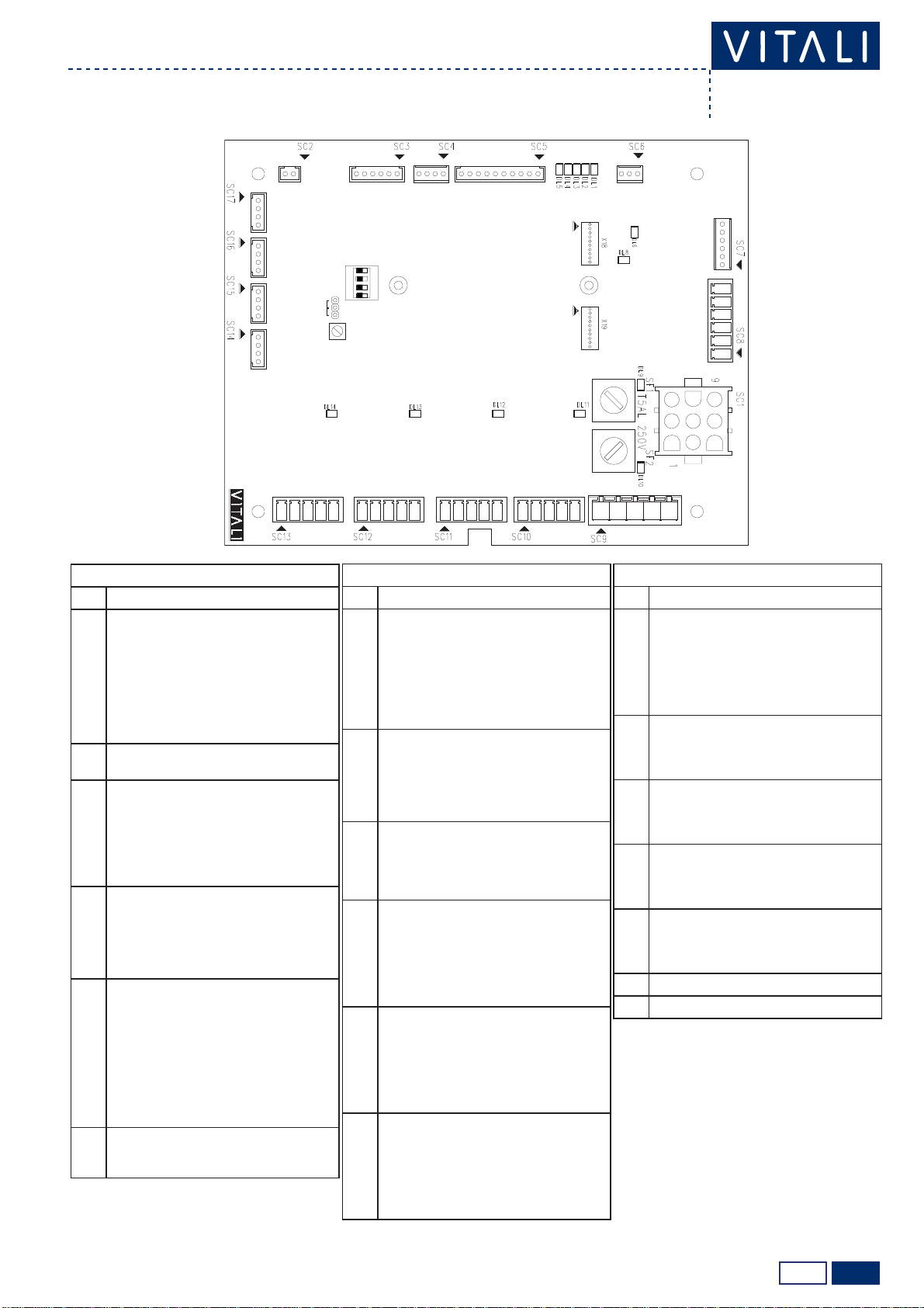
PCB COD. 59400052
Technical manual ›
T5 EVO/V8e COD. 66000024-EN - 01/01/2012
Instrument selection card Ref. 59400052
Operator table
CONNECTORS
N° DESCRIPTION
SC1
1 - IN 24 Vac
2 - Not connected
3 - Not connected
4 - IN 24 Vac (phase)
5 - CAN H (SERIAL COMMUNICATION)
6 - CAN L (SERIAL COMMUNICATION)
7 - IN + 34 Vdc
8 - IN +25 Vdc
9 - Ground
SC2 1 - Reserved
2 - Reserved
SC3
1 - +25 Vdc (Arm brake module supply cod. 59400053)
2 - Enable signal for arm brake (Connection to
arm brake module cod. 59400053)
3 - Ground (Arm brake module supply cod. 59400053)
4 - Not connected
5 - +24 Vdc arm brake solenoid valve
6 - Ground arm brake solenoid valve
SC4
1 - +25 Vdc
2 - CAN H (serial communication operator’s table
keyboard)
3 - CAN L (serial communication operator’s table
keyboard)
4 - Ground
SC5
1 - IN microswitch of instrument arm 1
2 - IN microswitch of instrument arm 1
3 - IN microswitch of instrument arm 2
4 - IN microswitch of instrument arm 2
5 - IN microswitch of instrument arm 3
6 - IN microswitch of instrument arm 3
7 - IN microswitch of instrument arm 4
8 - IN microswitch of instrument arm 4
9 - IN microswitch of instrument arm 5
10 - IN microswitch of instrument arm 5
SC6 1 - +25 Vdc
2 - 0÷5 Vdc (scaler power adjustment)
3 - Ground
CONNECTORS
N° DESCRIPTION
SC7
1 - Cont. normally open activation of brushless
micromotor
2 - Cont. normally open activation of brushless
micromotor
3 - 0÷5 Vdc (micromotor speed adjustment)
4 - Ground
5 - Serial communication brushless module (RX)
6 - Serial communication brushless module (TX)
SC8
1 - +34 Vdc (Brushless module supply)
2 - Ground
3 - Disconnected
4 - IN phase W brushless micromotor
5 - IN phase V brushless micromotor
6 - IN phase U brushless micromotor
SC9
1 - +34 Vdc AUX
2 - +25 Vdc AUX
3 - Ground
4 - 24 Vac (phase) AUX (e.g. syringe 6F)
5 - 24 Vac - AUX (e.g. syringe 6F)
SC10
1 - phase W brushless micromotor 1
2 - -electric micromotor 1 (phase V brushless
micromotor)
3 - + electric micromotor 1 (phase U brushless
micromotor)
4 - + illumination of instrument 1 (FO)
5 - - illumination of instrument 1 (FO)
SC11
1 - phase W brushless micromotor 2
2 - -electric micromotor 2 (phase V brushless
micromotor)
3 - + electric micromotor 2 (phase U brushless
micromotor)
4 - + illumination of instrument 2 (FO)
5 - - illumination of instrument 2 (FO)
SC12
1 - phase W brushless micromotor 3
2 - -electric micromotor 3 (phase V brushless
micromotor)
3 - + electric micromotor 3 (phase U brushless
micromotor)
4 - + illumination of instrument 3 (FO)
5 - - illumination of instrument 3 (FO)
CONNECTORS
N° DESCRIPTION
SC13
1 - phase W brushless micromotor 4
2 - -electric micromotor 4 (phase V brushless
micromotor)
3 - + electric micromotor 4 (phase U brushless
micromotor)
4 - + illumination of instrument 4 (FO)
5 - - illumination of instrument 4 (FO)
SC14
1 - Ground solenoid valves instrument 1
2 - Solenoid valve of chip blower instrument 1
3 - Solenoid valve of instrument spray 1
4 - Driving air/cooling solenoid valve instrument 1
SC15
1 - Ground solenoid valves instrument 2
2 - Solenoid valve of chip blower instrument 2
3 - Solenoid valve of instrument spray 2
4 - Driving air/cooling solenoid valve instrument 2
SC16
1 - Ground solenoid valves instrument 3
2 - Solenoid valve of chip blower instrument 3
3 - Solenoid valve of instrument spray 3
4 - Driving air/cooling solenoid valve instrument 3
SC17
1 - Ground solenoid valves instrument 4
2 - Solenoid valve of chip blower instrument 4
3 - Solenoid valve of instrument spray 4
4 - Driving air/cooling solenoid valve instrument 4
X18 Connection micromotor module cod.59400060
X19 Connection micromotor module cod.59400060
2/26.1
Technical manual ›
T5 EVO/V8e
COD. 66000024-EN - 01/01/2012
LED
N° INDICATION
DL1 It indicates the proper operation of the serial connection
DL2 It indicates when a direct (non-serial) input changes status
DL3 It indicates when a direct (non-serial) output changes status
DL4 It indicates the updating of the flash memory, flashing when the equipment is restarted after a new firmware is uploaded
DL5 Presence of 5 Vcc voltage
DL6 Activation of brushless micromotor
DL7 Activation of external circuit management of brushless micromotor (micromotor module Code 59400060 off)
DL8 Activated reverse rotation of micromotor
DL9 Integrity of fuse SF1
DL10 Integrity of fuse SF2
DL11 Activation of instrument 1
DL12 Activation of instrument 2
DL13 Activation of instrument 3
DL14 Activation of instrument 4
FUSES
N° PROTECTED PARTS VALUE AND
TYPE ANOMALIES THAT CAN BE DETECTED AFTER INTERRUPTION
FUNCTIONS LED
SF1 Parts 34 Vdc powered
T. 5AL (5x20)
DELAYED
Any eventual parts connected
to pins 1 and 3 of SC9 are not
working.
The micromotor or turbine that
can be modulated is not work-
ing.
DL9 switched off.
SF2 Parts 24 Vac powered
T. 5AL (5x20)
DELAYED
Any eventual users connected
to pins 4 and 5 of SC9 are not
working.
DL10 switched off.
JUMPER
N° FUNCTION STATUS
AB
J1 Reserved Reserved Normal operation (standard position)
N.B: for the proper operation of the card, each instrument must be properly configured (see chapter 6.7).
DIP-SWITCH PSW1
N° ON OFF
1 It identifies the card as secondary to the one that is present
in the operator’s table (e.g. an additional card for additional
instruments in the nurse’s console).
Standard position (card in the operator's table).
2 Reserved Reserved (standard position)
3 Reserved Reserved (standard position)
4Reserved Reserved (standard position)
TRIMMER
N° FUNCTION
RV1 Maximum voltage adjustment for handpieces illumination (FO) (standard ≈3.2 ± 0.1 Vcc, 0.700 mA)

6.2 1/1
PCB COD. 59400060
Technical manual ›
T5 EVO/V8e COD. 66000024-EN - 01/05/2011
Micromotor card Ref. 59400060
Operator table
CONNECTORS
N° DESCRIPTION
X18 X18 Selection card connection Code 59400052
(X18)
X19 X19 Selection card connection Code 59400052
(X19)
LED
N° INDICATION
DL1 It indicates the activation of the micromotor, its brightness is directly proportional to the speed of rotation.
This manual suits for next models
1
Table of contents
Other VITALI Medical Equipment manuals


