VITALI T5 User manual

T5 Re-Rm
Technician
EN


1
T5
CONTENTS
1 MANUFACTURER’S NOTES ON INSTALLATION ............................................................................................................................... 2
2 WARRANTY .................................................................................................................................................................................. 3
Circumstances not covered by warranty ................................................................................................................................................................ 3
3SYMBOLS USED ............................................................................................................................................................................ 5
4TECHNICAL SPECIFICATIONS ......................................................................................................................................................... 6
5FLARES CHAIR CONNECTION TEMPLATE ....................................................................................................................................... 6
6OVERALL DIMENSIONS ................................................................................................................................................................. 7
7INSTALLATION INSTRUCTIONS ...................................................................................................................................................... 8
Assembling the backrest ........................................................................................................................................................................................ 9
Assembling the backrest housing ........................................................................................................................................................................ 10
Mounting the dental unit bracket on the chair .................................................................................................................................................... 11
Assembling the water unit ................................................................................................................................................................................... 12
Assembling the instrument table arm .................................................................................................................................................................. 13
Assembling the tray table .................................................................................................................................................................................... 14
Grounding connection for water unit - dental unit bracket - instrument table arm ................................................................................................ 15
Water unit electrical connection .......................................................................................................................................................................... 15
Assembling the instrument table ......................................................................................................................................................................... 16
Hydraulic and pneumatic connections for the instrument table............................................................................................................................ 17
Electrical connections for the instrument table ..................................................................................................................................................... 19
Bowl suction and flushing connection ................................................................................................................................................................. 20
Hydraulic connection for water unit .................................................................................................................................................................... 20
Hydraulic and pneumatic connections to the connector block ............................................................................................................................. 21
Assembling the (optional) suction tube support arm and grounding connection .................................................................................................. 22
Setting the FLARES chair movement Dip-Switches ................................................................................................................................................ 23
8INSTALLATION INSPECTION ........................................................................................................................................................ 24
9SERIAL NUMBER LOCATION ........................................................................................................................................................ 25
10 ACCESSING THE INTERNAL PARTS - FLARES ................................................................................................................................. 26
Removing the derivative housing ........................................................................................................................................................................ 26
Removing seat upholstery ................................................................................................................................................................................... 27
Installing seat upholstery ..................................................................................................................................................................................... 27
Removing the coplanar headrest upholstery ........................................................................................................................................................ 28
Removing the double-jointed headrest upholstery ............................................................................................................................................... 28
Removing the backrest upholstery ....................................................................................................................................................................... 28
Removing the seat housing ................................................................................................................................................................................. 29
Disassembling the headrest bracket ..................................................................................................................................................................... 29
Removing the fixed armrest ................................................................................................................................................................................. 30
Removing the tilting armrest (optional) ................................................................................................................................................................ 30
Removing the lower parallelogram housing ........................................................................................................................................................ 31
Removing the upper parallelogram housing ........................................................................................................................................................ 31
11 FLARES ELECTRICAL UNIT ........................................................................................................................................................... 32
Replacing fuses ................................................................................................................................................................................................... 33
12 ACCESSING INTERNAL PARTS OF THE WATER UNIT ..................................................................................................................... 34
Available versions of the water unit ..................................................................................................................................................................... 36
13 PRESSURIZED BOTTLE KIT ........................................................................................................................................................... 37
Operating diagram of the pressurized bottle ....................................................................................................................................................... 38
14 DENTAL UNIT ELECTRICAL GROUP .............................................................................................................................................. 39
Setting the dental unit card dip-switches ............................................................................................................................................................. 40
Replacing the dental unit card fuses .................................................................................................................................................................... 40
15 ACCESSING THE INTERNAL PARTS OF THE INSTRUMENT TABLE .................................................................................................. 41
16 INSTRUMENT SELECTION CARD .................................................................................................................................................. 43
Electronic card fuses ............................................................................................................................................................................................ 43
17 ACCESSING THE INTERNAL PARTS OF THE ASSISTANT CONSOLE ................................................................................................. 44
Electrical connections for the assistant console .................................................................................................................................................... 46
18 HYDROPNEUMATIC ADJUSTMENTS ............................................................................................................................................. 47
Adjusting and setting the table instruments ......................................................................................................................................................... 48
Hydropneumatic diagram ................................................................................................................................................................................... 50
19 KEYPAD FUNCTIONS ................................................................................................................................................................... 51
20 ASSISTANT CONSOLE .................................................................................................................................................................. 53
Assistant/patient keypad functions (located on console) ....................................................................................................................................... 53
21 VITALI FOOT CONTROLS ............................................................................................................................................................. 54
Electronic foot control ......................................................................................................................................................................................... 54
Electronic foot control setting and configuration ................................................................................................................................................. 55
Two-lever foot control ......................................................................................................................................................................................... 56
22 SAFETY DEVICES ......................................................................................................................................................................... 57
23 SPECIAL MAINTENANCE ............................................................................................................................................................. 59
Replacing the vertical chair movement gearmotor ............................................................................................................................................... 59
Replacing the backrest actuator ........................................................................................................................................................................... 60
Adjusting the backrest movement cradle friction .................................................................................................................................................. 61
Adjusting the backrest movement mechanical memory ....................................................................................................................................... 62
Adjusting the vertical chair movement mechanical memory ................................................................................................................................. 62
Adjusting the instrument table support panel friction ........................................................................................................................................... 63
Assembling the table instrument cords ................................................................................................................................................................ 64
Replacing the bowl ............................................................................................................................................................................................. 64
Assembling the instrument table arm stop ........................................................................................................................................................... 65
Assembling the instrument table arm .................................................................................................................................................................. 65
24 MAINTENANCE ........................................................................................................................................................................... 66
Disinfecting ........................................................................................................................................................................................................ 67
Autoclavable parts .............................................................................................................................................................................................. 68
25 PERIODIC CHECKS ...................................................................................................................................................................... 69
Turbine lubrication oil recovery device ................................................................................................................................................................. 70
Checking the backrest protection brush ............................................................................................................................................................... 71
Checking the pull spools ..................................................................................................................................................................................... 71
Checking for wear on the gearmotor winding block ........................................................................................................................................... 72
Replacement of the cannula terminals and external suction hoses ....................................................................................................................... 73
Checking the internal suction hoses .................................................................................................................................................................... 73
Replacing the water unit filters ............................................................................................................................................................................ 73
Replacing the air unit filter .................................................................................................................................................................................. 74
26 REQUESTING SPARE PARTS AND MATERIALS ............................................................................................................................... 75
27 WIRING DIAGRAMS .................................................................................................................................................................... 77

T5
2
1 MANUFACTURER’S NOTES ON INSTALLATION
This technical manual, supplied to VITALI dealers, contains the information necessary in order to carry out
those tasks VITALI considers may be carried out by specially trained and authorized technical personnel.
VITALI may not be held liable for the safety, reliability or performance of the equipment if:
•installation, adjustments, changes or repairs have not been carried out by qualified dealer personnel;
•the electrical system of the room where the equipment is installed is not in compliance with current
regulations;
•the equipment is not used in accordance with the instructions.
The technical documentation supplied by VITALI along with the equipment contains all setting
instructions and other information that may be used by specially trained user personnel, to work on those
parts of the equipment that VITALI deems reparable by outside technicians.
VITALI declines all responsibility for personal injury or property damage derived from tampering by
unauthorized personnel, lack of or inadequate maintenance, the use of non-original spares or failure to
observe the instructions in the present manual.
This device must be used by qualified personnel only. VITALI shall not be liable for any direct or indirect
damages connected with improper uses or abuses of the equipment.
NOTE: The equipment is available in two versions, identified by different letter pairs
:
Re •Basic Version: includes manual chair controls (Optional: 1 working position definable during
installation).
Rm •Version with Memories: includes manual and automatic controls, definable by the user.

3
T5
2 WARRANTY
VITALI equipment is guaranteed ex works against defects in materials or workmanship for a period of twelve months
following installation.
Your VITALI Dealer will provide any repairs or replacements needed during the warranty period. Any repairs that
cannot be performed on-site will be carried out at authorized VITALI service centers. The customer will be charged
only for transport costs.
Circumstances not covered by warranty
The warranty shall not be upheld in the event of:
•installation was not duly carried out in accordance with the directions provided in the Installation Instructions;
•servicing has not been performed by qualified personnel authorised by VITALI;
•non-original spare parts have been used;
•the technical systems supplying the device (electricity, water, pneumatic supplies) have not been set up in
conformity with current technical standards and laws;
•supplementary equipment has been connected following the initial installation, exception being made for devices
authorised by VITALI;
•the operating and maintenance instructions contained in the documentation furnished by the manufacturer are
not complied with;
•the device identification label has been removed, erased or altered;
•the product displays damage caused by accidental impacts, faults or damage deriving from poor maintenance,
improper use or abuse of the equipment, improper supply systems, exposure to flames, spilling of liquids, natural
calamities, incompetence or any causes not ascribable to the manufacturer;
•the WARRANTY AND INSTALLATION CERTIFICATE has not been returned or registered by the user within 30 days
of the date of installation (or delivery). The user may also delegate the dealer to fulfil this requirement.
•The Warranty does not extend to ceramic parts, bulbs or any parts subject to wear or which have deteriorated
as a result of improper use or inadequate maintenance due to user negligence.
VITALI shall not be liable for inability to use the product caused by situations beyond its control, nor shall it be liable
for any damage incurred as a result of inability to use the product.
Any unauthorised servicing that results in an impairment of the essential safety features provided by the manufacturer
shall invalidate the CE DECLARATION OF CONFORMITY of the products.
Any parts to be replaced under warranty shall be returned to VITALI (together with the MAQ28 form) which shall
provide for shipment of the required spare part.
The Warranty does not provide for compensation of direct or indirect damages of any kind caused by eventual
defective equipment to people or things. VITALI shall freely decide whether to repair or replace defective products.
All products replaced or repaired under warranty shall be subject to a 6-month warranty, commencing from the
moment of repair or replacement.
Any spare parts sent under the clause “Anticipated replacement under warranty” shall be automatically invoiced
should the corresponding defective parts not be returned to Vitali within 15 days of the shipping date. For fiscal
reasons, spare parts shall be supplied under warranty provided Vitali has received the Certificate of Assembly and
Warranty containing all the client’s details.
The area dealer will be happy to provide you with any further information you may need.
T5
4
0476
è conforme ai requisiti essenziali di sicurezza della Direttiva 93/42/CE (D.Lgs.n.46/97) così come modificati dalla Direttiva 2007/47/CE (D.Lgs.n .37/2010)
complies with the essential safety requirements of the Directive 93/42/EC just as modified by the Directive 2007/47/EC
est conforme aux standards essentiels de sécurité de la Directive 93/42/CE ainsi que modifiés par la Directive 2007/47/CE
genauso der wesentlichen, wie von der Richtlinie 2007/47/EWG veränderten, Sicherheitsanforderungen der Richtlinie 93/42/EWG entspricht
FACSIMILE
5
T5
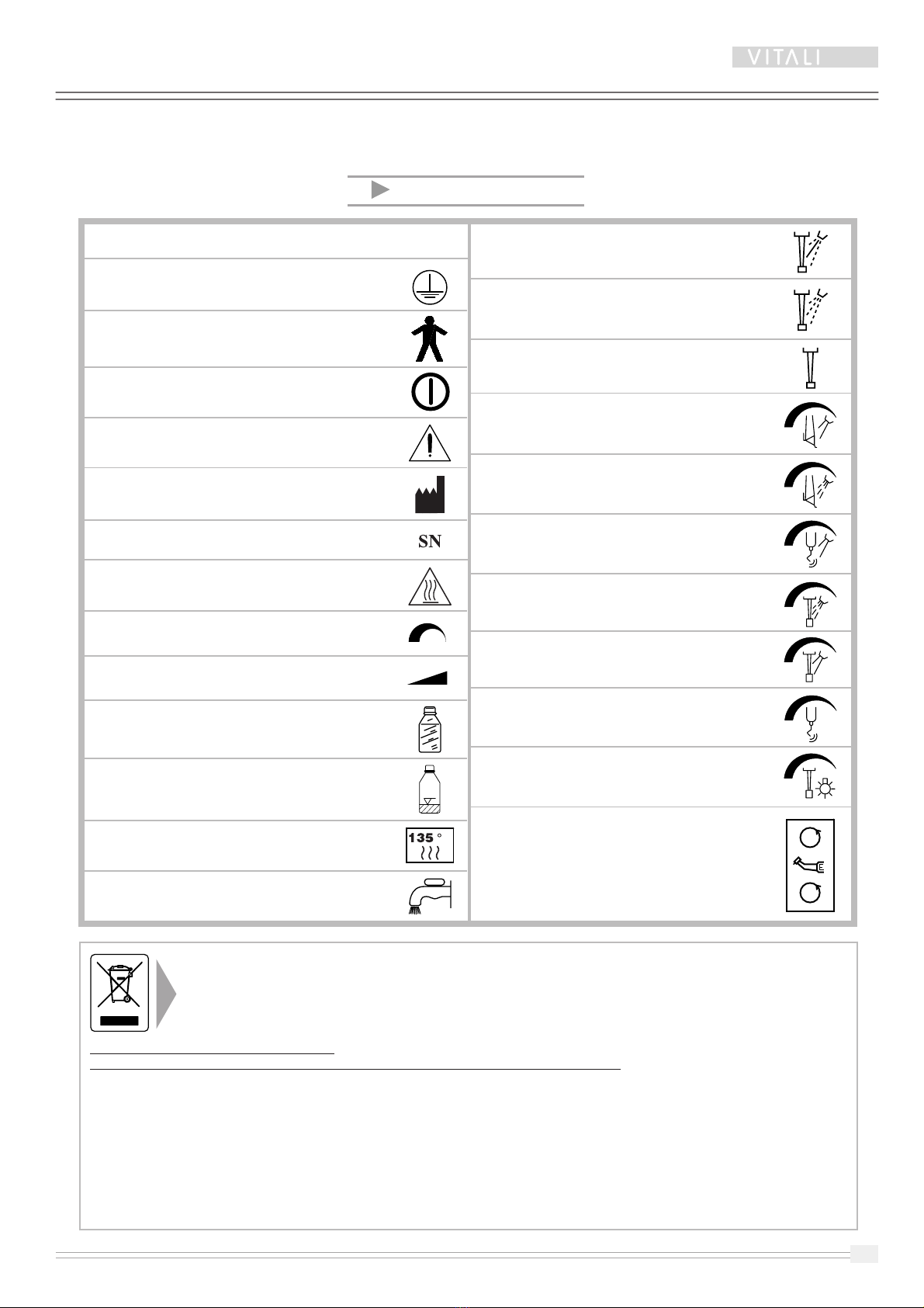
3 SYMBOLS USED
Activate spray instrument
Chip-Blower
Instrument on
Syringe water adjustment
Syringe air adjustment
Scaler water adjustment
Chip blower/spray air adjustment
Spray water adjustment
Scaler potentiometer
Instrument lighting brightness
adjustment
Micromotor rotation direction
reverse
Before disposal of waste produced during the use of the device or parts of the device itself, always carry out thorough
disinfection and ensure that all parts that are potentially subject to biological contamination are correctly packed.
Such parts must be disposed of in compliance with applicable national legislation and local bylaws.
The local VITALI Dealer will be glad to satisfy your queries on national and local laws on correct waste disposal.
Applicable only within EU countries
2002/96/EC Directive on Waste Electrical and Electronic Equipments (WEEE).
The symbol on the product means that, in the event of decommissioning, the device canot be disposed of as domestic waste, it must
instead be divided into its various component material types for sorted waste disposal.
The aim is to reduce the environmental impact of ANY electric or electronic equipment and minimize the volume of waste transported
to dumps. Correct disposal prevents potential damages to personal health and to the environment.
For this purpose, VITALI has complied with the obligations that statutory regulations place under the responsibility of the manufacturer.
The local VITALI Dealer will be able, if necessary, to give all information about.
The user can return the device to the manufacturer if a comparable device is purchased in its place. Improper disposal is punishable
by law.
Alternating current
Protective grounding
Type-B equipment
On / Off
General warning
Identification of manufacturer
Device serial number
Parts accessible with surface temperature
> 30 °C
Instrument function adjustment
Instrument rotation speed adjustment
Pressurized bottle
Pressurized bottle fluid level
Autoclavable device
Water mains
C
T5
6
4 TECHNICAL SPECIFICATIONS
This equipment must work in environments with a relative humidity between 45% and 75%, and with an
ambient temperature between 10 and 35 °C.
DENTAL UNIT
Model.......................................................................................................................................................... T5
Class (EN 60601-1) ................................................................................................................................. Class I
Class (Medical Devices Directive MDD) ................................................................................................. Class IIa
Protection rating ............................................................................................................................. Type B
Power supply............................................................................................................. 230 V 50-60 Hz 600 VA
Inlet air pressure ................................................................................................... min. = 5 bar ; max. = 10 bar
Inlet water pressure .............................................................................................. min. = 2 bar ; max. = 10 bar
Air minimum capacity ....................................................................................................................... 60 L/min.
Max. weight applicable to instrument tray .............................................................................................. 1,5 kg
Weight (Kg) ............................................................................................................................................ 40 kg
Filtering capability of suction filter ..................................................................................................... ø 0,8 mm
Filtering capability of bowl filter ......................................................................................................... ø 1,5 mm
Filtering capability of air filter.................................................................................................................. 20 μm
Filtering capability of water filter............................................................................................................. 80 μm
CHAIR
Modell ................................................................................................................................................ FLARES
Class (EN 60601-1) ................................................................................................................................. Class I
Protection rating .............................................................................................................................. Type B
Power supply............................................................................................................. 230 V 50-60 Hz 300 VA
Total weight ......................................................................................................................................... 127 Kg
Minimum seat height .............................................................................................................................. 45 cm
Maximum seat height ............................................................................................................................. 85 cm
Maximum seat width .............................................................................................................................. 50 cm
Total chair lift time .............................................................................................................................. ~ 15 sec
Total chair descent time ...................................................................................................................... ~ 15 sec
Total backrest lift time ......................................................................................................................... ~ 10 sec
Total backrest descent time ................................................................................................................. ~ 10 sec
☞WARNING! THE CORRECT OPERATING OF THIS EQUIPMENT DEPENDS ON THE
OBSERVANCE OF THE PARAMETERS ABOVE.
☞WARNING! THE EQUIPMENT IS NOT INTENDED FOR USE IN POTENTIALLY EXPLOSIVE
ATMOSPHERES (ATEX DIRECTIVE).

Ø 40.0
Ø 30.0
Ø 30.0
5 FLARES CHAIR CONNECTION TEMPLATE
SCALE 1:1
AIR
min. 5 Bar
max. 8 Bar
60 l/min.
COLD WATER
min. 2 Bar
max. 8 Bar
DENTAL UNIT DRAINAGE
FLARES CHAIR BASE PLATE
SEPARATOR
DRAINAGE
CENTRALIZED SUCTION
CONNECTION CONTROL
150 mm
365 mm
SUCTION
TUMBLER WITH TECHNICAL GASKET
FOR HOSE WITH OUTER DIAMETER 25
CONNECTION
AREA SECRETION SUCTION
PREPARE WITH TAPERED FITTING
FOR FLAT SPIRAL HOSE WITH INTERNAL DIAMETER 25
230 V AC 60 Hz
POWER SUPPLY
3/8 FITTING FOR 8x6 HOSE
TO BE EQUIPPED WITH CLOSING VALVE
3/8 FITTING FOR 8x6 HOSE
TO BE EQUIPPED WITH CLOSING VALVE AND
DE-COUPLER
USE 3 WIRES CROSS-SECTION 1.5 sqmm
MAIN ELECTRICAL POWER SUPPLY;
USE 3 WIRES CROSS SECTION 2.5 sqmm
DRAINAGE OF SECRETIONS FROM MINI-SEPARATOR
TO BE PREPARED ONLY
IF AIR RING SUCTION SYSTEM IS PRESENT
M12 LEVELING DOWEL
RUBBER PROTECTION


7
T5
6 OVERALL DIMENSIONS
Left-handed version Right version
T5
FLARES
13
85
45
176
62°
25°
SYNCHRONIZED TRENDELENBURG POSITION
90
°
R52 cm
90
°
97 cm
38 cm
176 cm
64 cm
80 cm
97 cm
133 cm 133 cm
178 cm
176 cm
64 cm
80 cm
R52 cm
R96 cm
178 cm
R96 cm
Connection area
62 cm
R56 cm
62 cm
R56 cm
SCALE 1:30
SCALE 1:20
T5
8
FB
A
D
E
GC
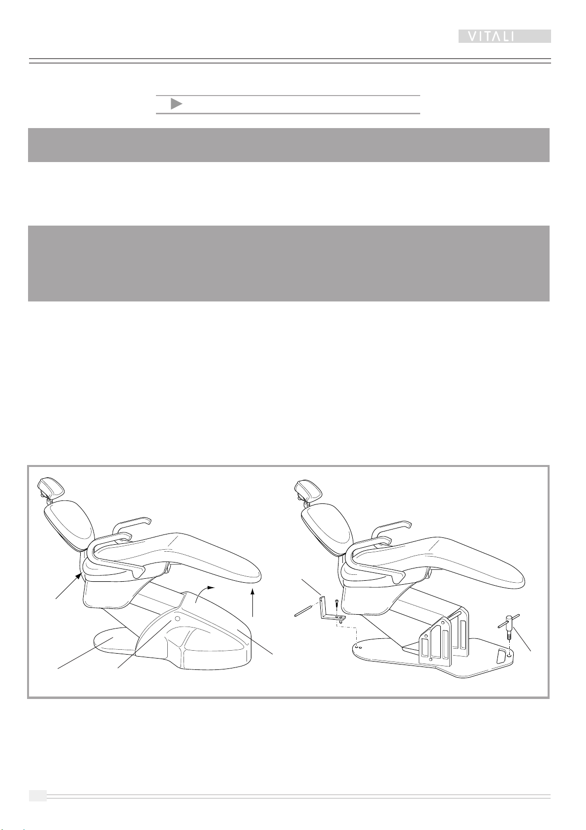
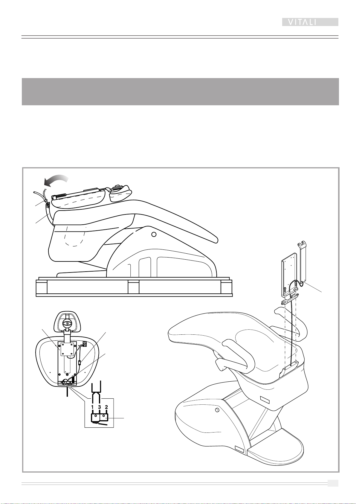
7 INSTALLATION INSTRUCTIONS
☞NOTE: For more details on removing the housing "F" and the seat upholstery, see the chapter on "Accessing
the internal parts - Flares".
PLEASE FOLLOW THE INSTRUCTIONS BELOW CAREFULLY
FOR INSTALLING THE FLARES CHAIR!
To avoid breaking the plastic housing, please use the special keys "A" and "B" supplied with the chair.
Use them as follows:
1) Power the chair at 230 V AC - 50/60 Hz - single-phase
WARNING!
The power supply cable should be directly connected to the electrical installation:
DO NOT make use of extension cables.
Each equipment have to be individually connected to a socket
through the provided plug, without using multiple outlets.
2) Press the main switch "C"
3) To raise the chair, use the foot control (if present) or dentist keypad, after connecting it to the connector CN20
of the chair card. In this case, see the chapter on "Setting the Chair Movement Dip-switches"
4) Remove the grey polyurethane cover "G" and tighten the key "A"
5) Remove the upholstery from the seat, pulling on points "D" and "E"
6) Remove the housing "F", after first turning the mobile part of the seat (see the chapter on "Accessing the
internal parts - Flares")
7) Tighten the key "B" in the point shown in the illustration
8) Move the chair by lifting it with the keys "A" and "B"
9) Remove the keys "A" and "B".
9
T5
Assembling the backrest
Proceed as follows to assemble the backrest:
1)
I
nsert the white Rilsan hose and electrical wires through the hole "H" on the base of the backrest frame "D"
2) Attach the backrest using the two M8 Allen screws "B" on the support "C"
3) Connect the white Rilsan hose to the quick fitting "E"
4) Connect the electrical cable to the microswitch "F" as shown in the illustration
5) Connect the grounding safety wire in point "G".
☞
NOTE: The Flares backrest is supplied disassembled and appropriately packed. During
installation, failure to correctly complete all of the connections shown will seriously
compromise the safety and proper operation of the equipment.
F
H
DE
B
C
G

T5
10
BB
Fig. 1 Fig. 2 Fig. 3
Backrest
structure
AC
A
D
Assembling the backrest housing
Proceed as follows to assemble the backrest housing:
1) Make sure the distance between the hooks "A" and the backrest structure is properly adjusted, to avoid
unnecessary strain when assembling the backrest upholstery, which could lead to breakage of the backrest
guard.
2) If necessary, correct the position of the hooks "A" by loosening the nuts "D". Tighten the nuts "D" when the
adjustment is complete
3) Tilt the backrest as shown in fig. 1 and fasten it using the hook "A". Pull downward until it is fully engaged with
the upholstery.
4) Fasten the guard in place using the two tapered screws "B" (fig. 2).
3) Finally, mount the headrest bracket release button "C" (fig. 3).
Perform the same steps in reverse order to remove the backrest housing.
11
T5
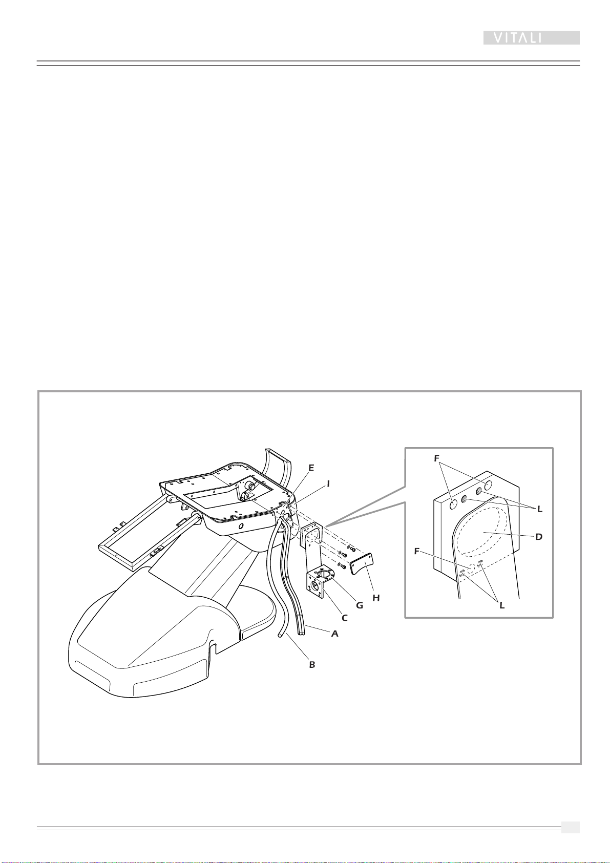
Mounting the dental unit bracket on the chair
Proceed as follows:
1) Insert the tube bundle “A” (bundle of electrical cables clamped to the ribbed grey suction hose id. 25 and the
sheath containing the air and water intake hoses) through the hole “D” in the bracket “C”.
2) Insert the hose "B" (transparent Armovin water drainage hose diam. 20x27).
3) Attach the bracket in area "E" through the holes "F" using the three M10 Allen screws.
4) Level using surface "G" as a reference by means of the four M10 dowels "L" and tighten the three M10 Allen
screws.
5) After fastening the bracket, cut the plastic clamps on the bundle of hoses "A".
6) Fit the closing guard "H" on the seat guard "I" and fasten by means of the countersunk screws M6 supplied.
7) Cover the M6 screws using the two white covers supplied.

T5
12
B
C
A
LEFT-HANDED DENTAL
UNIT BRACKET
WATER UNIT FRAME VIEWED
FROM BELOW
N°2 Allen screws
Type M8, mounted by us
LEFT-HANDED
VERSION
Assembling the water unit
Follow the instructions below to assemble the water unit:
1)
Use the 3 M8 Allen screws “A” to fasten the water unit, inserting them through the holes “B” in the bracket “C”.
RIGHT
VERSION
B
C
A
RIGHT-HANDED DENTAL
UNIT BRACKET
WATER UNIT FRAME VIEWED
FROM BELOW
N°2 Allen screws
Type M8, mounted by us
13
T5
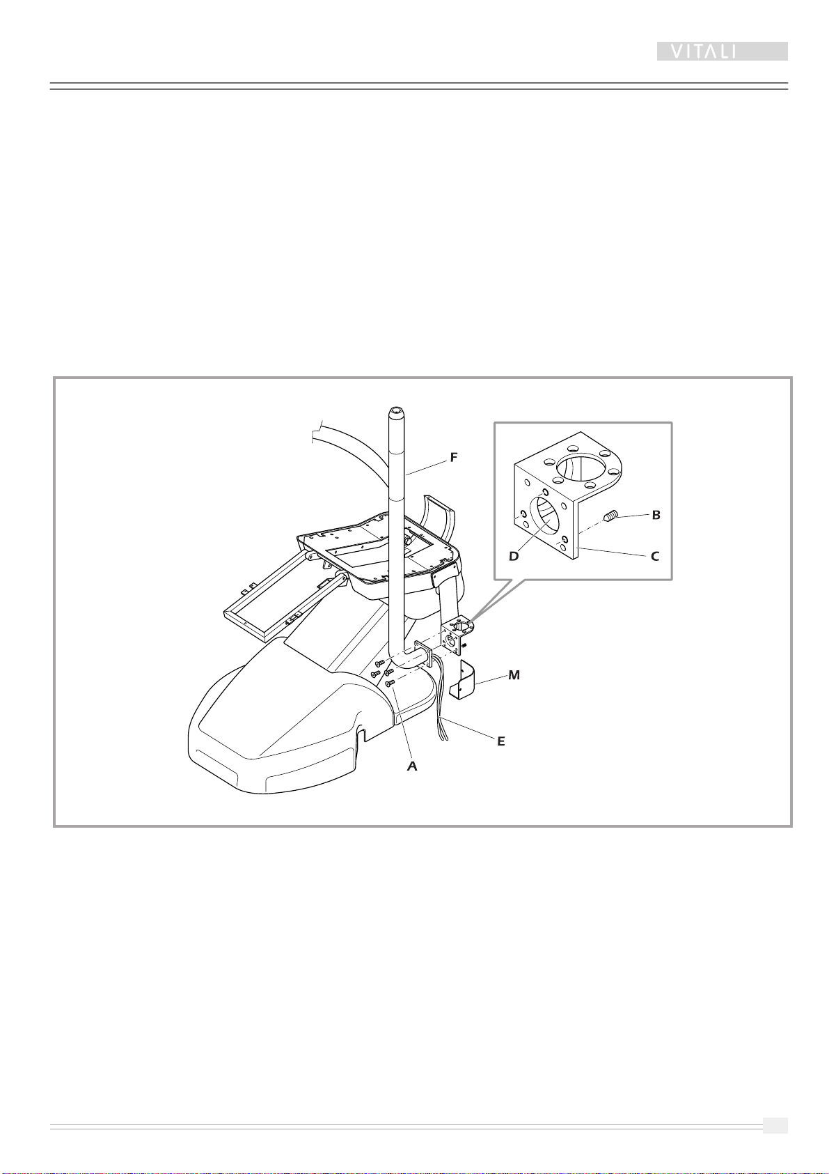
Assembling the instrument table arm
Proceed as follows to assemble the instrument table arm:
1) Insert all of the cables and hoses “E” from the instrument table arm through the hole “D”
2) Secure the tray table to the dental unit bracket with the four M8 screws “A” provided, level the arm with the three
M10 dowel pins “B” located on side "C".
3) Level using surface "F" as a reference allowing for possible bending and tighten the four Allen M8 screws "A".
4) Tighten the three M10 dowels "B" to avoid losing the leveling adjustment.
5) After installation, apply protection guard "M" on the bracket "C" by means of the two M5 screws.
T5
14
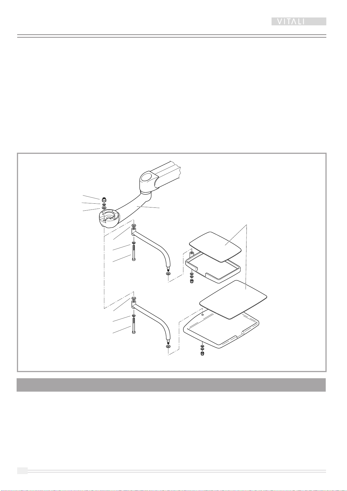
The tray table is supplied assembled. Fasten it to the instrument table support “A” as follows:
1) Use the M12 Allen screw “B” to fasten it to the instrument table support “A”, making sure to insert the nylon
washers "C", "D", "E" and the metal washer "F".
2) Finally, adjust the correct friction by means of the M12 nut "G".
Assembling the tray table
☞NOT
E: maximum weight applicable to the tray table = 1.5 kg.
A
G
F
E
D
C
B
D
C
B
Silicone protection,
washable in autoclave

15
T5
☞
NOTE:
The water unit, instrument table arm
and dental unit bracket are supplied
disassembledandappropriately packed. During
installation, failure to correctly complete all of
thegroundingconnections shown will seriously
compromise the safety and proper operation
of the equipment
CORRECT GROUNDING
CONNECTION
Grounding connection
water unit - dental unit bracket - instrument table arm
Water unit
electrical connection
1 2 3 4 5 6 7 8
ON
59400001
☞NOTE:Connect the connectors to the
card indicated, respecting the
numbering marked on the
connectors (see paragraph "Dental
Unit Electrical Group").

T5
16
Assembling the instrument table
To access the interior of the instrument table, see the chapter on "Accessing the internal parts of the instrument
table".
Before fastening the instrument table, insert all of the cables from the support “A” through the hole “C” at the bottom
of the instrument table.
Use the 3 M8-screws “B” provided to fasten the instrument table to the support “A”.
C
A
CLUTCH
MECHANICAL
STOP
NOTE: CHECK THE SERIAL NUMBER ON THE
BOTTOM OF THE INSTRUMENT TABLE, TO MAKE
SURE IT MATCHES THE ONE SHOWN ON THE
SERIAL NUMBER PLATE OF THE WATER UNIT.
B
This manual suits for next models
1
Table of contents
Other VITALI Medical Equipment manuals


