Vitec Multimedia aktiv6 User manual

aktiv6, 8, 8T Fluid Head
User Guide
S2064S aktiv6
S2068S aktiv8
S2068T aktiv8T
EN www.sachtler.com
aktiv6, aktiv8, aktiv8T Fluid Head

Copyright © 2022
All rights reserved.
Original Instructions: English
All rights reserved throughout the world. No part of this publication may be stored in a retrieval system, transmitted, copied or reproduced in any
way, including, but not limited to, photocopy, photograph, magnetic or other record without the prior agreement and permission in writing of the
Videndum Group Plc.
Disclaimer
The information contained in this publication is believed to be correct at the time of printing. Videndum Production Solutions Ltd reserves the right
to
in new versions of the publication.
Should this publication not contain information on the core functionality of your product, please let us know. You may be able to access the latest
revision of this publication from our website.
Videndum
Trademarks
All product trademarks and registered trademarks are the property of The Videndum Group Plc.
All other trademarks and registered trademarks are the property of their respective companies.
Published by:
Videndum Production Solutions Ltd
Email: technical.publications@Videndumgroup.com

Contents
Safety.....................................2
About this Guide............................ 4
Intended Use ............................. 4
About this User Guide ...................... 4
Warranty ................................ 4
Extended Warranty ........................ 4
Serial Number Location..................... 4
Box Contents .............................. 5
Optional SpeedSwap Accessories ............. 6
Operating Elements . . . . . . . . . . . . . . . . . . . . . . . . . 8
Left View ................................ 8
Right View ............................... 9
PrismBubble ............................ 10
1st Time Installation........................ 11
...... 11
. 13
Operation.................................16
Attaching, Levelling and Dismounting Head .... 16
........ 18
..... 20
Fitting the Pan Bar........................ 22
Adjusting the Pan Bar ..................... 22
................... 23
Balancing the Payload..................... 24
....... 24
............... 26
............... 26
Adjusting the Drags ....................... 28
Transportation Head Settings ............... 29
Transporting with the Pan Bar ............... 29
Maintenance .............................. 30
................... 30
...................... 30
Routine Maintenance ..................... 30
Bowl Connector Trouble Shooting ............ 31
Technical Specication ..................... 32
General Notices ........................... 33

2
Safety
Important information on the safe installation and operation of
this product. Read this information before operating the product.
For your personal safety, read these instructions.
Do not operate the product if you do not understand how to use
it safely.
Save these instructions for future reference.
Warning Symbols Used in these Instructions
Safety cautions are included in these instructions. These safety
instructions must be followed to avoid possible personal injury and
avoid possible damage to the product.
!
WARNING!
Where there is a risk of personal injury or injury to
others, comments appear supported by the word
‘WARNING’.
Health and Safety
!
WARNING! Risk of personal injury or injury to others. All
personnel must be fully trained and adhere to correct manual
responsibility of the local organisation to enforce safe working
practices at all times.
Mounting and Installation
!
CAUTION!
Where there is a risk of damage to the product,
associated equpment, process or surroundings,
comments appear supported by the word ‘CAUTION’.
Refer to the product instruction manual.
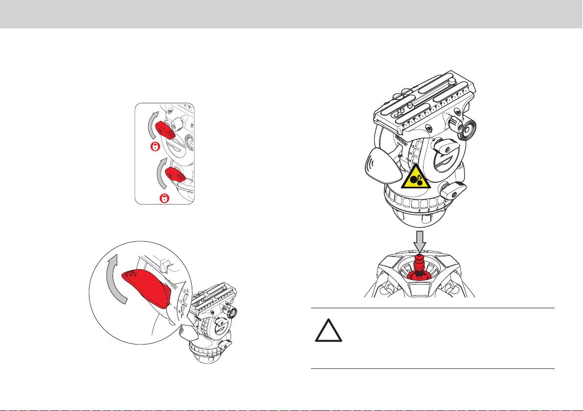
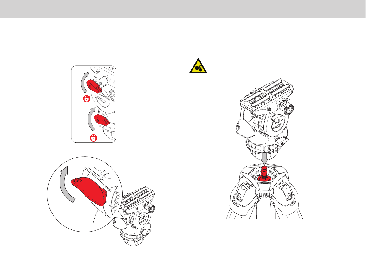
WARNING!
caution.
TM
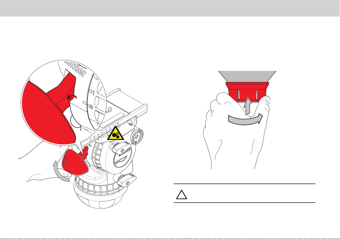
Risk of nger entrapment. When removing the head
from the tripod, take care the SpeedLevel Lever does not
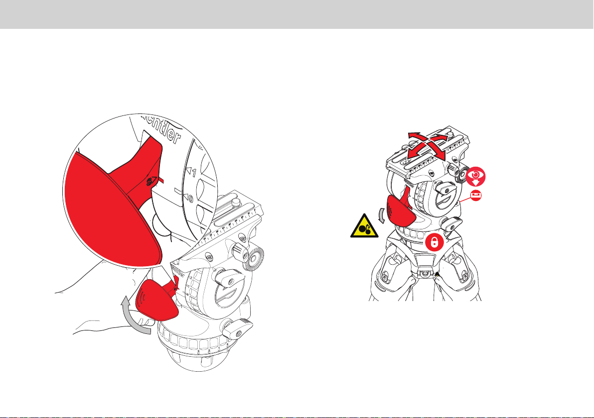
WARNING! Risk of nger entrapment. Do not place
head
!
WARNING! Do not
support the combined mass of the head and its full
payload.
!
WARNING! Avoid unintentionally lifting the SpeedLevel
Lever above the detent as the head will be released
suddenly from the tripod.
!
CAUTION! Always lock the horizontal and vertical brakes
when the camera is mounted but not in use or when level-
!
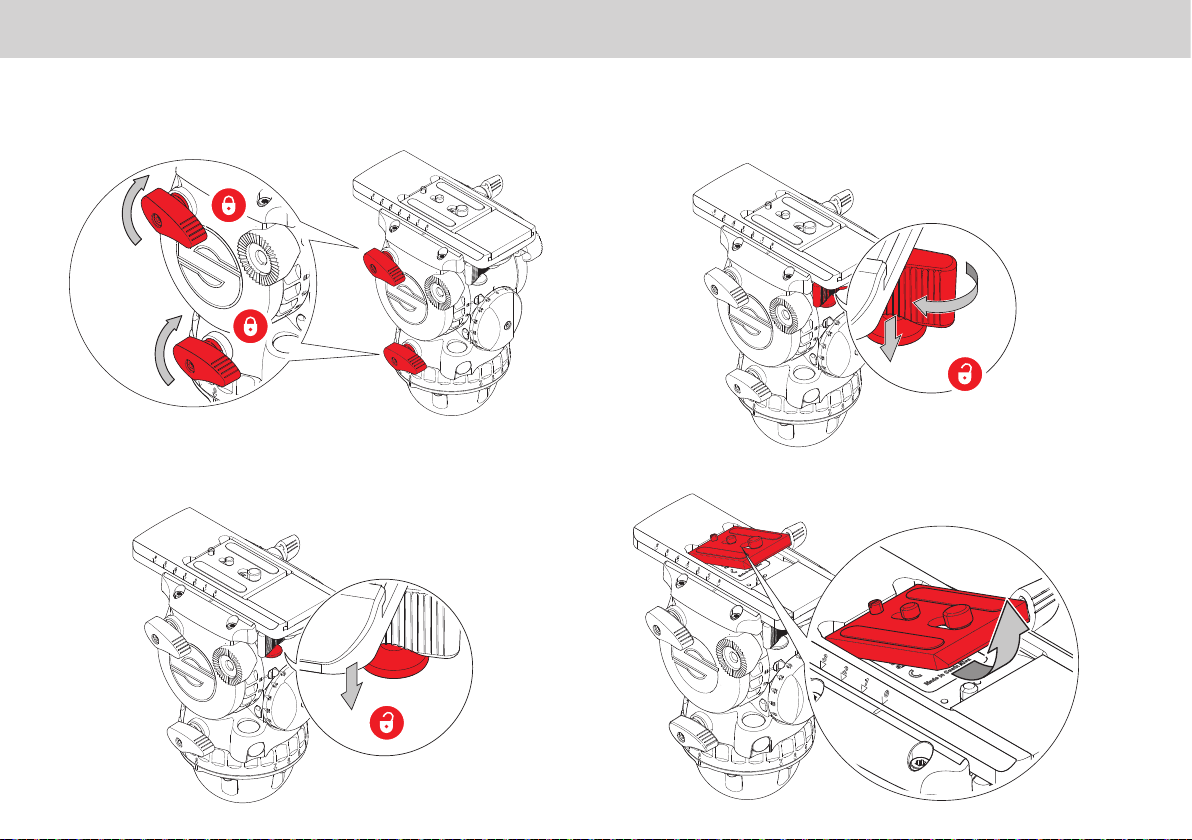
CAUTION! Hold the camera securely when mounting or
adjustments to the tripod height or footprint.
!
CAUTION! Always hold the pan bar when making
adjustments to the counterbalance or camera position. Do
not
!
CAUTION! Do not attach heavy items to the pan bar.
!
CAUTION! Always remove the camera before
transporting.

3
Safety
Maintenance
!
WARNING!
accessories or servicing by non-approved personnel could
terms and conditions of the product warranty.
!
CAUTION! When replacing the battery, only use the same
or an equivalent type of battery recommended for use with
this product.

4
About this Guide
pan and tilt movement giving the operator total image control through
a wide range of angles.
This user guide has been produced to instruct the user on the correct
Intended Use
About this User Guide
Warranty
This product is covered by a one year warranty.
The warranty will be invalidated if:
• The head is improperly installed or used in a manner contrary to
this user guide.
• The head housing is opened by unauthorised personnel.
Extended Warranty
Please register at www.sachtler.com for an extended warranty
period.
Serial Number Location
Located under the camera plate on both Touch and Go and Sideload
cradles.

5
Box Contents
Item Description Part No
1 S2064S
aktiv8 S2068S
1a S2068T
2aktiv75 bowl connector S2080-0012
3 0364
4Sideload camera plate S 0164
5Pan bar plus right 0992SP
6User guide S2068-4980
6
OR
1a

6
Optional SpeedSwap Accessories
S2080-0003
S2080-0012 S2080-0005
Adaptor aktiv head / slider 75 mm
aktiv bowl connector 75 mm
Adaptor aktiv slider / tripod 75 mm

7

8
Operating Elements
Left View 1Rosette for left pan bar
2Vertical brake
3Horizontal brake
4Horizontal drag control
5SpeedLevel Lever
6Vertical drag control
7Sideload plate lock
8Spare camera screws
9Illumination for drag and counterbalance
10 Levelling bubble
11
12 Sideload system safety lock
Touch & Go System
Sideload System
2
3
6
4
5
8
1
7
12
9
10
11
8

9
Operating Elements
1Sideload camera plate
1a
2Rosette for right pan bar
3Bowl
4
5Balance plate clamp knob
6
Right View
Sideload system
Touch & Go System
1
3
2
4
6
1a
5

10
Operating Elements
PrismBubble
easy levelling in poor lighting conditions.
The head also features a prism to view the bubble when the head is
switch.
In addition the PrismBubble may be lit on its own or with the control
LED’s to enable setup up in low light conditions.
The illumination will be activated by pushing the bubble prism window.
1.
approx.10s ± 1s.
2. Pressing and holding the window for >1s will turn on the level
bubble LED and all control LED’s for 20s ± 2s.
3. Pressing the window again when any of the illuminations are on,

11
1st Time Installation
Connector StudAdjustment Knob
Fitting 75 mm Bowl Connector For The 1st Time
further adjustment required.
Prepare the Bowl Connector
adjustment knob.
The assembly is supplied unscrewed but loosely assembled.
To aid with tting of the Bowl Connector
for the rst time, it is highly recommended
to view the installation video. This will help
ensure correct installation.
Scan the QR Code to see installation video or
type into browser:
sachtler.com/aktiv-head-installation

12
1st Time Installation
Install Bowl Connector to Tripod
1.
2.
bowl.
Align
ats
Visual markers show the
location of the ats
3.
4. Push up the adjustment knob outer ring and keep pushing while
turning clockwise.
5.
bowl.
Note! The goal here is not to fully clamp the tripod as would be
done with a traditional tie down, but to leave a small amount of
spring free-play felt when the stud is pushed from above. If too tight
the head will not latch properly.
6. Final adjustments will be made in the following section.

13
1st Time Installation
1.
with one hand.
Mounting the Head and Setting Connector Tension
2. Lift the SpeedLevel Lever as shown all the way to the top.
3.
SpeedLevel Lever.
!
CAUTION! Try to lift the head from the tripod to ensure it
has latched onto the connector. If the head lifts free of the
connector the clamp has been tightened too much and
will require loosening. With the head removed turn the
the connector by repeating steps 2 and 3.

14
1st Time Installation
4. To set the connector tension, raise the tripod so the head is at eye
level.
5. Lift the SpeedLevel Lever on the head and hold with “S mark”
aligned to the Setting mark on the body.
6.
ring and turning clockwise to remove the clearance.
`
!
CAUTION! DO NOT over-tighten, the objective is to eliminate
a gap rather than attempting to tighten in the same manner as
a tie down.

15
1st Time Installation
45°
60°
7. The tension is correct when the SpeedLevel Lever is released and
sits between approximatel
from the body of the head as shown in the diagram below.
loose, repeat steps 5 and 6.
Approximately 45° to 60° from the body
!CAUTION! Push the SpeedLevel Lever fully closed against
the head body before use.
!CAUTION! Try and lift the head to ensure the head is fully
secured to the tripod.

16
Operation
WARNING!
Attaching, Levelling and Dismounting the
Fluid Head From the Tripod
Attach Head to Tripod
1. Apply the brakes.
2. Lift the SpeedLevel Lever as shown all the way to the top.
3.
SpeedLevel lever.
CAUTION! Push the SpeedLevel Lever fully closed against the
head body before use.
CAUTION! Try and lift the head to ensure the head is fully
secured to the tripod.

17
Operation
Dismounting the Fluid Head
To release the head from the tripod, lift the SpeedLevel Lever to the top
and lift the head away from the tripod.
With the head removed carefully lower the SpeedLevel Lever.
Levelling the Fluid Head
1.
To level the head lift the SpeedLevel Lever until the head is free
2.View the bubble from above, or through the horizontal prism
3.
re-adjust if required.
CAUTION! Push the SpeedLevel Lever fully closed against the
head body before use.

18
Operation
Mounting and Dismounting the Camera (Touch and Go)
1.Apply the horizontal and vertical brakes.
2.Hold the camera plate or camera with one hand. Grasp the locking
button.
3.With the safety button held down, move the locking lever
as far as possible to the left.
4.The camera plate or camera will be released from the
sliding balance plate.
This manual suits for next models
5
Table of contents
Other Vitec Multimedia Camera Accessories manuals
Popular Camera Accessories manuals by other brands

VADDIO
VADDIO OneLINK Installation and user guide

NOVOFLEX
NOVOFLEX Panorama VR-System Mini manual

Broncolor
Broncolor Scoro S WiFi / RFS 2 operating instructions

Ikelite
Ikelite 6241.13 Supplemental instructions

GreenWorks
GreenWorks BAB740 Operator's manual

Panasonic
Panasonic AW-360C10 operating instructions