Vitek VTC-TNB5RFEA-2 User manual

VITEK
VITEK
VTC-TNB5RFEA-2
Transcendent Series 5 MegaPixel Fixed
IP WDR Bullet Camera
QUICK START GUIDE
FEATURES:
• 1/2.7” 5.0 Megapixel CMOS Image Sensor
• Up to 20fps@5MP (2880 × 1620), Up to 30fps@4MP (2560 × 1440), 3MP
(2304 × 1296), 1080P (1920 × 1080), 720P (1280 × 720), D1, 480× 240, CIF
• 2.8mm Fixed Iris Lens
• Matrix IR (up to 100’ IR Range)
• True Wide Dynamic Range (120dB)
• True Mechanical Day/Night function by ICR
• XD-DNR (3D & 2D-DNR) Noise Reduction
• Region Intrusion Detection, Object Abandoned / Missing, Scene Change Detection, Line
Crossing, Video Blur, Video Color Cast Detection
• H.265+ / H.265 / H.264+ / H.264 / MJPEG
• MicroSD Card Slot for Local Recording (Up to 256GB)
• 1 Ch. Audio In + Built-in Mic*
• Remote Viewing via CMS, IE (plug-in required)/Google Chrome/Edge/Firefox/Safari,
and iOS & Android Apps
• ONVIF Compliant
• IP67 Weather Resistance
• Wall Mount Included & Optional Junction Box (VT-TJB08) Available
See Additional Mounting Options on Pg. 9
• 12VDC & PoE (Power over Ethernet) Operation
• 3-Year Warranty
*Please research local, state and federal lawsregarding the implementation
of audio surveillance.
PLEASE NOTE:
Complete User Guide, Software, Tools, and Updates are
available online. Scan the QR Code or visit:
http://www.vitekcctv.com/Downloads

2 3
Components and Accessories
Cable Connections
Overview
First connect the weather resistant cap to an ethernet patch cable,
then connect the cameras ethernet adaptor. If not powering the
camera with PoE, also connect the power cable to an approved
12VDC power supply.
Camera
Quick Guide
Screws
Drill Template
Plastic Plugs
Network Coupler
DC12V
Weather Resistant Security Cap
2
1
3
4
5
7
6
1. Locking Ring
2. Mounting Base
3. Network Connector
4. Audio Input
5. Power Connector
6. MicroSD Card Slot
7. Reset
8. Mic
8

3
Installation
Before beginning installation, make sure that the wall or ceiling is
strong enough to withstand 3 times the weight of the camera. The
mounting steps are as follows:
1. Attach the drill template to
the place where you want to
install the camera, then drill
3 screw holes and 1 cable
hole (if you want to route the
cables through the mounting
base) according to the drill
template
MicroSD Card Installation: Remove the plastic cover (a) from the
camera, then loosen the two screws on (b). Remove (b) and insert
card before re-installing (b) and (a).
Weather Resistant Network Coupler
1. Loosen the nut from the Weather Resistant Network Coupler,
2. Run ethernet cable through coupler, then attach a RJ-45 connector.
3. Tighten the nut and coupler for a weather resistant seal.

4 5
2. Route the cables and connect the power & video cables, use the
rubber plug to fill the gap of the mounting base. then secure the
mounting base to the ceiling or wall with screws.
3. Loosen the locking ring to adjust the Pan and Tilt of the camera,
then tighten the locking ring to secure the viewing angle adjust-
Locking
Ring

5
LAN Configuration
The camera can be accessed on the local network either using the
IP-Tool or directly in a web browser.
Accessing the Camera Using the IP-Tool
1. Make sure the camera and PC are connected to the LAN.
2. Locate the IP-Tool installer at www.
vitekcctv.com/Downloads/Soft-
ware/Transcendent-IPTool_v2.0.2.zip
, then install on the PC. Open
the installed application.
3. Modify the IP address. The default IP address is 192.168.226.201.
Click the information of the camera listed in the above table to show
the network information on the right side. Modify the IP address and
gateway of the camera and make sure its network address is in the
same local network segment as the computer’s. Please modify the
IP address of your device according to the practical situation.
For example, the IP address of your computer
is 192.168.13.4. So the IP address of the
camera shall be changed to 192.168.13.X.
After modification, please input the password
of the administrator and click “Modify” button
to modify the setting.
** Default admin password: “123456".
MENU
IP Camera
Net wor k Cabl e Net wor k Cabl e
Swi tch
Router Computer

6 7
4. Double-click the IP address and then the system will pop up the web
browser to connect IP-CAM . IE browser will download the Active X
control. After downloading, a login window will pop up as shown
below:
Input the user name and password to log in.
Default user name: admin / Default password: 123456.
Directly Access Through a Web Browser
The default network settings are as shown below:
IP address: 192.168.226.201 HTTP: 80
Subnet Mask: 255.255.255.0 Data Port: 9008
Gateway: 192.168.226.1
You may use the above default settings when you log in the camera for
the first time.
1. Manually set the IP address of the PC. The network segment should
be the same as the default settings of IP-CAM. Open the network
and share center. Click “Local Area Connection” to pop up the
following window.
Select “Properties” and then select Internet protocol according to the
actual situation (for example: IPV4). Next, click “Properties” button to
set the network of the PC.

7
2. Open the IE Browser and input the default address of IP-CAM and
confirm. The IE browser will download Active X control.
3. After downloading Active X control, the login dialog box will pop up.
4. Input the default username and password and then enter to view.
WAN Configuration
Access the camera by the router or virtual server for example.
1. Make sure the camera is connected to the LAN; Then log into the
camera via LAN and go to System Congfig→Network Config→Port
menu to set up the port number.
2. Enter System Config→Network Config→IP Address menu to modify
the IP address.
4. Open the web browser and input its WAN IP and HTTP port to
access the IP-CAM.
3. Go to the router’s management interface through IE browser to
forward the IP address and port of IP-CAM in the “Virtual Server”.
5. For additional setup, features and functions, please scan
the QR code on the front page of this quick guide and
download the complete manual.

8 9
Image Sensor
Image Size
Resolution
Min. Illumination
Electronic Shutter
Lens
IR LEDs (Range)
Video Compression
Audio Compression
Main-Stream
Sub, Third Stream
Bit Rate / Type
Wide Dynamic Range
Digital Noise Reduction
Other Features
NDAA Compliant
Image Setting
Analytics
Smart Alarm
General Functions
Region of Interest (ROI)
Hardware Reset
Analog Video Output
Audio
Local Storage
Remote Viewing
Supported Browsers
Connection Protocol
Weather Resistance
Power Input
Power Consump 12VDC, PoE
Working Environment
Weight Net (Shipping), Dimensions L×W×H
1/2.7” 5.0 Megapixel CMOS Image Sensor
5 MegaPixel (2880 × 1620)
Up to 20fps@5MP (2880 × 1620), Up to 30fps@4MP (2560 × 1440), 3MP (2304 × 1296), 1080P (1920 × 1080), 720P (1280 × 720), D1, 480× 240, CIF
0.007 lux @F1.6, AGC ON; 0 lux with IR
1 s ~ 1 / 100000 s
2.8mm Fixed Iris Lens, FoV H: 110.5°, FoV V: 57°, FoV Diag: 131°
1 Matrix Style IR (up to 100’)
H.265+ / H. 265 / H.264+ / H.264 / MJPEG
G.711A / G.711U
5MP(1~20fps)/4MP/3MP/1080P/720P(1~30fps)
720P/D1/ CIF (1~30fps), 60Hz: D1/480× 240/CIF (1~30fps)
64 Kbps ~ 8 Mbps / VBR + CBR
120dB WDR
3D-DNR
Back Light Compensation, Highlight Compensation
Yes
ROI, Saturation, Brightness, Hue, Contrast, Wide Dynamic, Sharpness, Image Mirror, Image Flip, NR
Region Intrusion, Abandoned Object, Scene Change, Line Crossing, Video Blur, Video Color Cast Detection
Motion Detection, SD Card Error, SD Card Full
Watermark, IP Filter, Video Mask, Illegal Login Lock
Each ROI to be configured separately
Yes
No
1 Ch. Audio In + Built-in Mic*
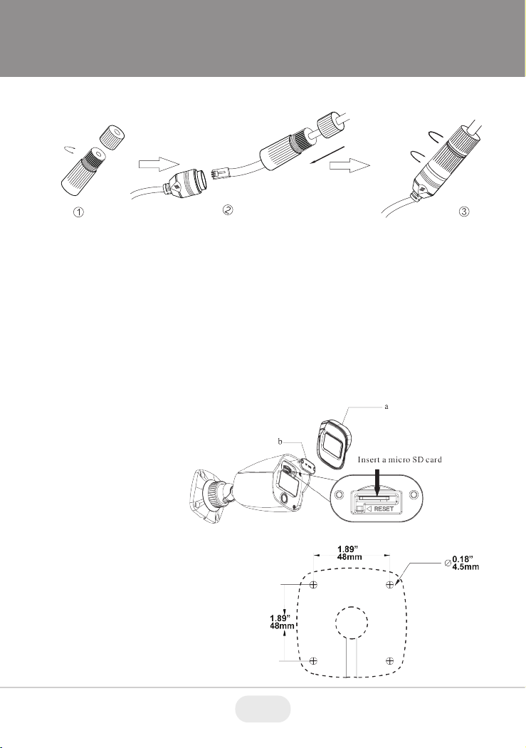
Built-in Micro SD card slot up to 256GB
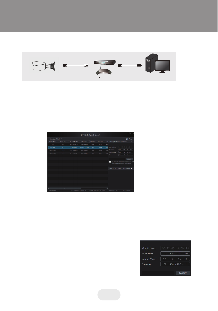
CMS / Web Browswer / iOS & Android Apps
IE (plug-in required) / Google Chrome / Edge / Firefox / Safari
ONVIF
IP67
12VDC / PoE
300mA (LEDs Off) / 600mA (LEDs On), <6W
-22°~140°F (-30°C ~ 60°C) / < 95% Humidity
14.11oz / .88lb / 400g (19.40oz / 1.21lb / 550g), 6.60 ×2.94 ×2.94” (167.6 ×74.7 ×74.7mm)
VTC-TNB5RFEA-2 Detailed Specifications
*Please research local, state and federal laws regarding the implementation of audio
surveillance.

9
VT-TPLMT
Transcendent
Universal Pole
Mount - Ivory,
reqs. VT-TJB08
VT-TCNMT
Transcendent
Universal Corner
Mount - Ivory,
reqs. VT-TJB08
OPTIONAL ACCESSORIES
AND RELATED PRODUCTS
FOR VTC-TNB5RFEA-2
VT-TJB08
Optional Junction Box
8.46”
6.43”
8.46”
8.47”

10 11
OPTIONAL ACCESSORIES AND
RELATED PRODUCTS FOR
NDAA COMPLIANT
TRANSCENDENT IP CAMERAS
VT-TNR1626PN
VT-TNR414PN
VT-TNR818PN
• 8MP (4K) HDMI Output
• H.265S / H.265+ / H.265 / H.264 Video Compression
• Analytic Support Including Basic Face Detection,
License Plate Recognition, and More!
• Available in 4, 8, and 16 Channels
• Up to 24TB Depending on Model (12TB per HDD)
• PoE Support on ALL Models
A Standalone Solution with
Analytic Support and
NDAA Compliance!
TRANSCENDENT NVRs

11
Also Consider Vitek NDAA Compliant Wireless
Access Points to Reduce Costly Cable Installation!
VT-WAP1150 and VT-WAP2150 High Speed 5.8GHz DIP
AP / CPE Wireless Bridge w/ 8MB Storage, 64MB RAM,
150MBps transmission, and Point-to-Multi-Point (P2MP)
Topology
With high speed transmission of 150Mbps and a wireless range
of 3000ft. (VT-WAP1150) and 1.25 miles (VT-WAP2150) these
products eliminate the need for expensive and troublesome long-
distance cables in areas where CCTV monitoring and rigorous
surveillance take place. These small, lightweight and durable units are
easy to install and easy to use with an innovative and straightforward
10-button plug-and-play dip switch that facilitates the creation of a
robust wireless network without a computer. Set-up can be simply
configured for point-to-point or point-to-multipoint topology depending
on the application, with up to 128 IP group configurations!
VT-WAP1150 VT-WAP2150

28492 CONSTELLATION ROAD VALENCIA, CA 91355
WWW.VITEKCCTV.COM
Version 1.1
June 2022
LIMITED PRODUCT WARRANTY
VITEK products carry a three (3) year limited warranty. VITEK warrants to the
purchaser that products manufactured by VITEK are free of any rightful claim
of infringement or the like, and when used in the manner intended, will be
free of defects in materials and workmanship for a period of three (3) years,
or as otherwise stated above, from the date of purchase by the end user.
This warranty is nontransferable and extends only to the original buyer or end
user customer of a VITEK Authorized Reseller.
The product must have been used only for its intended purpose, and not
been subjected to damage by misuse, willful or accidental damage, caused
by excessive voltage or lightning.
The product must not have been tampered with in any way or the guarantee
will be considered null and void.
This guarantee does not affect your statutory rights.
Contact your local VITEK Reseller should servicing become necessary.
VITEK makes no warranty or guarantee whatsoever with respect to products
sold or purchased through unauthorized sales channels. Warranty support is
available only if product is purchased through a VITEK Authorized Reseller.
Table of contents
Other Vitek Security Camera manuals

Vitek
Vitek VTD-MVH2910 User manual

Vitek
Vitek Transcendent Series User manual

Vitek
Vitek Transcendent Series User manual

Vitek
Vitek VTC-LED667HRCB User manual

Vitek
Vitek VTC-C750 User manual

Vitek
Vitek VTC-IRLED30A User manual

Vitek
Vitek VTC-IRH70 User manual

Vitek
Vitek VTC-C770DN User manual

Vitek
Vitek VTC-C594DN User manual

Vitek
Vitek VTC-HOCRBD2812 User manual

Vitek
Vitek VTC-C770/WDR User manual

Vitek
Vitek VTC-IRLED30A User manual

Vitek
Vitek VTC-IRLED24H User manual

Vitek
Vitek VTD-TND4RMS User manual

Vitek
Vitek VTD-VH49VP4 User manual

Vitek
Vitek VTC-BHOCRAZ User manual

Vitek
Vitek VTD-TND4RFA4 User manual

Vitek
Vitek VTC-HD713A User manual

Vitek
Vitek VTC-HD713A User manual

Vitek
Vitek VTD-A4F/IB User manual