VITO Vitolux VXI-4 Series User manual

Conte•tl
1 SafetyPrecaution•
and
ProductModel................................................................................
..
....................................... 1
1,1
Safety
Preaudions
...........................................................................................................................
..
.......
..
... 1
1,2 NameplateIntroduction:.................................................................................................................
....
.....
....
. 1
1.3 VFD Serles
Type
...........................................................................................................................................2
1.4
Technkal
Index
IUld Spedfication.......................................................................................................
..
.......2
2 Inatallation andWiring..................................................................................
..
....................................................
..
.......4
2.1 OperationEnTironment.................................................................
..
.............................................................S
2.2 In.tailingDirection
and
Space ...........................
..
...................................................................................
....
s
2.3 Appearance
and
Dimension
of
Keypad....................................................................................................... s
2,4
Whole Structure...................................................................................................................................
..
...
..
6
2.5
Batie
Riinning
Wiring......
..
....
.
....
.
....
..
....
.
....
.
....
..
....
.
....
.
....
..
....
.
....
.
....
..
....
.
....
.
....
..
....
.
....
..
....
.
....
.
....
...
..
.......
...
6
2.6 MajorLoop
Termiml
Wiring............................
..
..............................................................
..
..............
..
....... 7
2.7 MajorLoop
Termiml
Diagram.........................
..
...................................................................................
....
7
2.8 ControlLoop TerminalDiagram............................................................................................................
....
7
2.9 ControlLoop TerminalFunction Table ..................................................................................................... 7
2.10 DialSwitch................................................................................................................................................ 8
2,11
Wuing
Notiees
..
..................................................................
..
..............................
..
..........................
..
.........
..
9
3 OperationPanel
and
OperlltionMethod .................................................................................................................... 9
3.1 Operation PanelKe)'I ................................................................................................................................ · 9
3.2 LED aodIndicator
Light
De1eription1
..
.
..
.......
..
.......
..
.........................................................
..
................... 10
3.3 MonitoringParameterDiaplay....................................
..
................
..
.......
..
.................................................. 10
3.4
Run Statu1 ParameterDiaplay....................................................................................................
..
.............· 11
3.5 Malfunction
Alarm
Dllplay..................
..
.........................................................
..
......................................... 11
3.6 Function CodeEditing Diaplay.......................................................................................................
..
.....
..
..
· 12
3.7 MonitoringParameter................................
..
................
..
.......
..
..............................................................
..
..
. 12
3.8 Function CodeSetting................................................................................................................................. 13
3.9 U1er Pu1WordSetting
and
Function Code
Edit
.
..
.......
..
..
..
............
..
...
..
................
..
.......
..
.......
..
...
..
.......
..
..
..
13
4 Function
Parameter
Table
and
De1eription............................
..
.......
..
..............................
..
.........................
..
.............. 15
4.0
MonitoringParameter
Group
IUld
Fault
Record
.......................................................................................
15
4.1
Function Code.............................................................
..
..............................................................................
18
4,2 DetailedFunctionDeleription
..
......................................................................................................
..
.......
..
·45
F8
Proce.11
PID
Parameter
..
...........................................................................................................................79
F9
ProgrammableOperationParameter .......................................................................................................
84
FA
Protection Parameter
..
...............
..
....
..
...........................
..
.....................
..
....
..
...........................
..
.........
..
····92
FB
Communication
Parameter
.........................
..
.......................................
..
............................................
..
....97
FC
AdvanceFnnctionParameter
and
PerformanceParameter ....................................................
..
..............98
FE
Panel
F11Dction
Setting
and
ParameterManagement
(PD
group
re.erved)
.....
..
.......
..
...........
..
............ 102
5 CommunicationProtocol........................................................................................................................................... 108
5.1
RTU mode
IUld
format...................................................................
..
.......
..
................................................ 108
5.2 Regi8ter
Addrell
andFunction Code .....................................................
..
................................................ 108
5.3 Functions ofotherRegiaterAddre11: .....................................................
..
................................................ 1
13
5.4 FaaltCodes ...........................................................
..
.....................
..
......................................................... 114
5.5 Pre-alarmCode
of
theDriver:..............
..
.........................................................
..
...........................····.....··· 115
5.6 ControlCommand
Format
(seefanctien code 06H example)s
..
.......
..
.......
..
...........................................
11
5
5.7 ParameterAttrlbnte1 ..........................
..
................................................
..
......................................
..
........ 1
16
5.8
Error
Codefrom Slave Relponse
of
AbnormalInformation1 ..............
..
.......
..
.......................................
116
5.9 Comm
uni
cation Add
raa
ofal1Paramet12"1: .......................................................................................... 116
6 Troubleshooting........................................................................................................................................................ 1
17
6.1
Faalt
information
and
Troubleshooting ..............................................................................................
..
... 1
17
6.2 AbnormalPhenomena Solutl.on ...
..
................
..
............
..
.................................................................
..
........ 119
7 Maintenance........................................
..
.......
..
.......
..
........................................................................................
..
........ 1
21
7.1 Roatine Malntenance............................
..
........................................................................................
..
........ 1
21
7.2 PeriodicMaintenance .....................................................................................................................
..
........ 121
1
Slife•
Precautions
and
Product
MOdel
1.1 SafetyPn:caution1
..t..
Do
not install this equipment
in
anexplosive
gas
atmosphere, or there
will
be explosionhazards.
..t..
Only
qualified individuals should proceed with wiring. or
the.re
will
be electric
shock
hazards.
Do
not
conduct
any
wiring during the system poweron
to
avoid
the
electric shock..
..t..
Do
not
touch
control
termina.ls
,
in1ema.I.
circuit boardandits components,
or
the.re
willbe electric shock hazar
d.
..t..
Earthterminal
IIl1l8t
be exactlygrounded whenusinginverter. Grounding must be confirmedwith
the
national electric
safetyregulation
and
other
electric code.
..t..
Afterpower ott;
do
not touch internal circuit board
or
any parts inside within5 minutes after
keyp
ad
di
splay wento
ff.
Any
intemal operation must be after making sure of discharge off with instrument checking
to
avoid the electric
shock.
..t..
Do
not connect AC
power
to
output terminal
(U
,
V,
W)
of inverter. The only terminal
the
AC
power
allowed
to
be
connected
is
R,
S, T (or
Ll
, L2 single-phrase sourceinverter
).
..t..
Static electrici
ty
on human bodycan
damage
MOS device. Donot
touch
PCB andIGBTwithout anti-static measure.
..t..
Do
not lose screws, spacers andother metallic fureign bodies inside the driver
to
avo
id
fire hazardanddri
wr
damage.
..t..
Do
not connect 220VAC power to
intema1
control terminal
of
th
e driver, or there will be serious
dama
ge
to
the
dri
ver.
..t..
If
ovcn:urrmtprotection occurs afterstart
the
driver, confirm again
the
cxtemal wiring and thenpower on and
nm
the
driver.
..t..
Do
not switch offthepower
to
stop the dri
ver.
Cut offpower source after
the
motor stops running.
..t..
Do
not install
the
driverinplaces wi
th
direct
sunlight
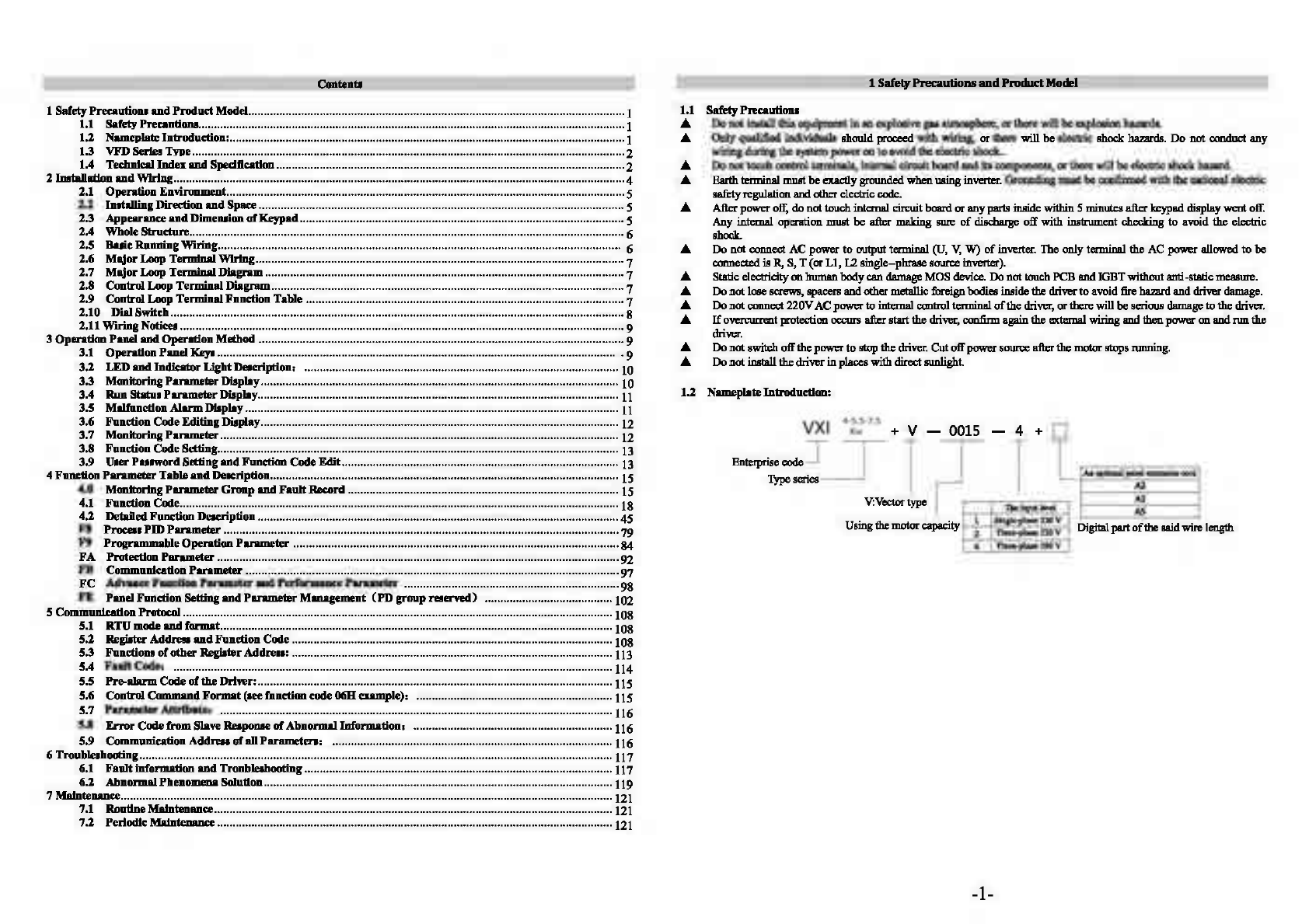
1.2 NameplateIntroduction:
VXI 4-5.5-7.5 + v - 0015 - 4 +
Kw
Enteiprise code .J
-r
T
~
Type
sc:nes
__J
I
V:Vector
type
Using
the
motor capacity
Tboinput i.v.J
I 1
S~
e
220V
I 2 fhre&.p
bue
220 v
Di
gitalpartof the said wire length
I 4
'fhrO&.pbuo
380v
-1-
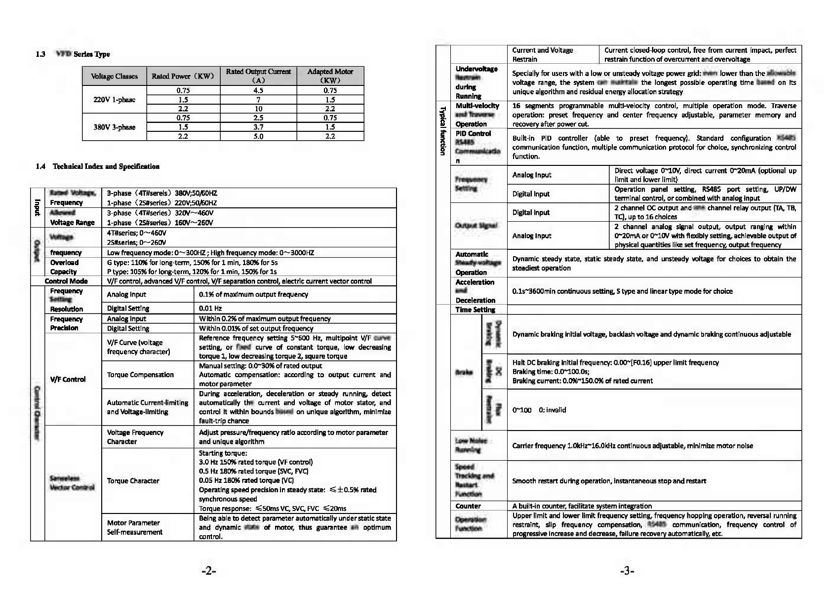
1.3
VFD
SerlesType Current and Voltage ICurrent closed-loop control, free
from
a.irrent impact, perfect
Restrain restrainfunction
of
overcurrent and overvoltage
Voltage
Classes
Rated
Power
(KW)
RatedOutput
Cunm
.Adapted Motor
(A)
(KW
)
0.75 4.5 0.75
220V
I-phase 1.5 7 1.5
2.2 10 2.2
0.75 2.5 0.75
380V
3-phase 1.5 3.7 1.5
2.2 5.0 2.2
1.4
Technieal
Index
and
Specification
Undervolt:qe
Specially
for
users
with
a
low
or
unsteadyvoltage
power
grid: even
lower
than
the
allowable
Restrain
during
voltage range,
the
svstem can maintain
the
longest possible operating
time
based
on
Its
Running uniquealgorithm and residual energy allocation strategy
~
Multl-veloclty
16
segments programmable multi-velocity control, multiple operation mode. Traverse
"a
andTnvene operation: preset frequency and center frequency adjustable, parameter
memory
and
[ Operation recovery
after
powercut.
2' PI
DConlrol
Built-in
PIO
controller
(ab
le
:I
to
preset frequency). Standard configuration
RS485
a..
RS485
0 CommunlQIUo communication function, multiple communication protocol
for
choice, synchronizing control
:I
function.
n
Analog
Input
Direct voltage
o-1ov,
direct current
0-20mA
(optional
up
Frequency
limit
and
lower
limit)
Rated
Voltage,
3-phase (4T#sereis)
380V;SOfoOHZ
S' Frequency 1-phase (2S#series)
220V;S~HZ
"a
a
Allowed
3-phase (4T#series)
320V-460V
Voltage
Range
1-phase (2S#series)
160V-260V
Voltage 4T#series;
0-460V
0 2S#serles;
0-260\/
c
..
frequency Lowfrequencymode:
0-300HZ
; Highfrequency mode:
0-3000HZ
"a
a OVerlmd Gtype:110%
for
long-tenn, 150%
for
1 min, 180%
for
Ss
capacrtv
Ptype: 105%
for
long-term, 120%
for
1 min, 150%
for
ls
Settin1 Digital Input Operation panel setting,
RS485
port
setting, UP/OW
tenninalcontrol,
or
combined withanalog
input
DigitalInput 2 channel oc
output
and one channel relay
output
(TA,
TB,
TC),
up
to
16
choices
OUtputSignal 2 channel analog signal
output,
output
ranging
within
Analog
Input
0-20mA
or
o-1ov
with
flexiblysetting, achievable
output
of
physical quantitieslikesetfrequency,
output
frequency
Automatic
Dynamic steady state, static steady state,
and
unsteady voltage
for
choices
to
obtain
the
Stady-voltage
Operation steadiest operation
Control
Mode
V/Fcontrol,advanced V/Fcontrol, V/F separation control, electric current vector control Acceleration
Frequency Analog
Input
0.1%
of
maximum
output
frequency
Setting
and
o.1s-3600mincontinuous setting,Stypeand lineartypemode
for
choice
Deceleration
Resolution Digital Setting 0.01
Hz
Time
Setting
Frequency Analog
Input
Within
0.2%
of
maximum
output
frequency
Precision Digital Setting
Wlthln
0.01%
of
set
output
frequency
V/F Curve{voltage Reference frequency setting
5-500
Hz, multipoint V/F curve
frequency character) setting,
or
fixed
curve
of
constant torque,
low
decreasing
torque
1,
low
decreasing
torque
2,
square
torque
Manualsetting: 0.0-30%of rated
output
V/F-
Control TorqueCompensation Automatic compensation: according
to
output
current
and
6'
motor
parameter
:I
During acceleration, deceleration
or
steady running, detect
..
2.
AutomaticCurrent-limiting automatically
the
current and voltage of
motor
stator, and
g
and
Voltage-llmltlng
contro
l
It
within
bounds based
on
unlque algorithm, mlnlmlze
• fault-trip chance
i1
it Voltage Frequency Adjust pressure/frequency ratio according
to
motor
parameter
..
Character and uniquealgorithm
Startingtorque:
gJ
!i
i il Dynamicbraking initialvoltage, backlashvoltageand dynamic braking continuousadjustable
-3
ill;;·
gJ
Halt
DC
braking initialfrequency: 0.00-[F0.16)upper
limit
freq
uency
Brab
I~
Brakingtime: 0.0-100.os;
::I Brakingcurrent:0.0%-150.0%
of
rated
ament
....
!
l!
0-100
O:inllillid
!!l.
Ii
a
Low
Noise Carrierfrequency1.0kHZ-16.0kHzcontinuous adjustable, minimize
motor
noise
Running
3.0
Hz
150%rated
torque
(VF
control)
senseless
0.5
Hz
180%rated
torque
(SVC,
FVC)
Torque Character 0.05
Hz
180%rated
torque
(VC)
Vector
Control Operating speed precision
in
steadystate:
~±0.5%rated
synchronousspeed
Torque response:
~SOms
VC,
SVC,
FVC
~20ms
Motor
Parameter Being able
to
detectparameterautomaticallyunderstaticstate
Self-measurement and dynamic state
of
motor, thus guarantee an
optimum
contro
l.
Speed
Tracking
and
Smoothrestartduringoperation, instantaneous
stop
andrestart
Restart
Function
Counter A built-
in
counter, facilitate system integration
Operation Upper
limit
and
lower
limit
frequency setting, frequency
hopp
in
g operation, reversal running
Function restraint, slip frequency compensation,
RS485
communication, frequency control
of
progressive increase
and
deaease, failure recoveryautomatically,etc.
-2- -3-

:II
i
iii
Output frequency,
output
current,
output
voltage,
motor
speed, set frequency, module
..
, temperature,
Pl
Dsetting.feedback, analog
input
and
output
.
2 2 i.
..
.;
0
J f i
The
latest 6 faults record; running parameters record when
the
latest
fault
trippinghappens
i
~
including
output
frequency, set frequency,
output
current,
output
voltage,
DC
voltage4 and
~
moduletemperature.
OVercurrent, overvoltage, undervoltage, modulefault, electricthermal relay, overheat, short
ProtectiveFunction circuit, defaultphase
of
input
and output,
motor
parameteradjustmentabnormality, internal
memory
fault, etc.
Ambient
-lo"C-+40"C
(please
run
the
VFD
In derated capacity
when
ambient temperature
Is
40"C
m
Tempe111ture
-so"C)
i
..
Ambient
g S%-95%RH,
without
condensing drops
3
Humidity
..
a Surroundings Indoors
(without
directsunlight, corrosllle
or
flammable gas, oilfog and dust)
Altitude
Running
in
deratedcapacity above 1000m,derate 10%
for
every1000m rise.
~
Protection IP20
c
level
ii
Coollng
!i
Air
cooling
with
fan
control
..
Method
Installation
Method
Wall-hangingtype,cabinet type
2 IBl1allation
and
wiring
1.
Ensure
the
power
hasbeen
cut
offbefore
wiring.
Electricchockand firehazard.
2.
Askelectric
eftlineerin1
professionals
to
conduct
wiring.
Electricchock and fire hazard.
3.
Earthterminals
must
be
reliable lll'Ounded.
(380Vclass: especially
the
third
grounding)
Electricshockand
flre
hazard.
DANGER
4.
Check
If
ItsactionIseffective
after
emergency
bnke
termlnal
Isconnected.
Injuryrisk(wiring responslbllltyshould be beard byusers).
5.
Do
not
touch
output
termlnals directly.The
output
terminal
Isconnected
dlrectly
to
motor.There should
be
no
short
circuitbetween
output
termlnals.
Electricshockand
short
circuithazard.
6.
Install
the
terminal
cover
beforepower on,
and
ensure
~r
off
when
dismantling
the
termlnal
cover.
Electricshockhazard.
7.
Conduct check and maintenance
after
s~a
minutes
after
power
off
when
internal residual electricity isdischarged
completely.
Hazard
of
residual voltage
in
electrolyticcapacitor.
-4-
CAUTION
1.
Check
If
the
voltage
of
power
Inlet
wire
agrees wltfl rated
Input
voltage
ofVFD.
Injuryand
fire
hazard.
2.
connect
brake resistor
or
brake
unit
according
to
wiring
diagram.
Fire hazard.
3.Choose screw
driver
and wrench
with
specified
torque
to
fastenterminals.
Fire hazard.
4.
Do
not
connect
the
power
Input
wire
to
output
U,V, W termlnals.
It
will
cause internaldamage
to
VFD
if
load
the
voltage
on
output
terminals.
5. Do
not
dlsrnantle
the
front
panel cover,
only
the
terminal
clM!r
needs
ta
be
dlsmantled
when
wiring.
It
maycause
lntemal
damage
to
VFD.
2.1 Operation Environment
<D
No corrosive
gases,
vapors,
dust
or
oily
dust
, nodirectsunlight.
@ Nofloating
dust
and metalparticle.
@ Ambient
humidity
20%-90%
RH.
@ VibrationlessthanS.9rn/s2(0.6g).
@ No electromagneticinterference.
@ Ambienttemperature-10"C-40"C. Ensuregoodventilation when ambienttemperatureexceeds 40"C.
Q)
Use
electric cabinet
or
remote control metnod
in
non-standard operation environment and ensure good ventilation
and heat dissipation. The service life of
VFO
lies in installing
env
ironment and operation condition.
But
even
in
standard
environment, a long-term continuous running can guarantee a life
of
no
more than 5 years
for
electrolytic capadtor and
about
3 years
for
coolingfan.
An
update
or
athorough maintenance
in
advance
is
recommended.
2.2 InstallingDirection
and
Space
To
ensure agoodcoolingcycle,
the
VFD
must
be
Installed vertically, and keepenough space
from
surroundings.
2.3
Appearuce
and
DimensionofKeypad
-
74.0mm
-
000000
c=
·
~
0000
0000
L70.
0mm
I
E
E
0
~
I
17.
0mm
14
.
0mm
-5-

2.4 Whole Structure
2.5 BasicRlllll1ing Wiring
90.
0
••
s.
0
••
31.0
..
~O
.
0
••
I
D
~
The wiringparts
of
VFD
include majorloopand control loop. Open
the
cover
of
1/0
terminals, users
can
see
the
majorloop
terminal and control loopterminal,
and
mustconduct
the
wiring according
to
the
following diagram.
.,____}
""'--
,_____!
I
A01
@ @
I
(DC0-10\I)
~
A02
All
(DC/4-2CJmA)""'"""I
COM
GND @
-6-
i
j
i
2.6
Major
Loop
Termlml
Wiring
2.7
Major
LoopTerminalDiagram
R
s
T
• +
PB
u
v
w
@
EBEBEB
EB
EBEB
EB
EB
EB
R
S{,
Tiu
P+
PB u v w
~
2.8 Control
Loop
TerminalDiagram
+l
OV
GND
AOl
W + 485-
X2/RBV
X4
X7/XP
Yl
+24V
'nil
IEBIEB
I
EBI
EB
IEBIEBIEBIEB
I
EB
I
EB
IEBI
IEBIEBIEB
I
EBI
EB
I
EB
IEBIEBIEB
I
EB
I
EBI
Al
l
AI2
Gl'irD
AOl/DO
X1J9WD
Xl
X5
(X)M
Y2
T
Al
TC
l
2.9 ControlLoopTerminalFunction Table
FunctioalllSoecllkatioa
of
Control
Loon
Terminal
Category Terminal Functions Specification
Number
Xl
X2
Effective when short circuit between(Xl,
X2,
)(3,
X3
X4, XS, X6, X7, XS)
-COM,
and
the
functions
are
Multi-functional
X4
set
by
parameters F7.00-F7.07 (common port:
Digital Input
X5
COM)
INPUT,
0-24V
level signal, low
level effective,
SmA.
Tenminal
X7
X6
can
work
as
one
of
the
multi-functional
X6
terminals, also
as
high-speed pulse Input
te
rminal
withprogramming, see
F7.05.
Yl
Multi-functional programmable collector open
circuit output channel 2,
can
be
programmed
as
OUTPUT,
maximum load
Digital Output
Y2
DO
terminal
of
various functions (common port: currentsSOmA.
COM)
Tenmrnal
Can
be
programmed
as
impulse outputtenminal
of
OUTPUT,
frequencyoutput
DO
various functions
as
many
as
13
kinds (common rangeF6.32-F6.35, set maximum
port:
COM).
See
F6.23.
frequency
as
high
as
SOKHz.
All
receives voltage/current input. Jumper
CN4
Analog
Ail
(for
jumper
terminal
All)
can
select voltage
or
INPUT,
input voltage range:
o-
Input/Output current input mode,
and
voltage input is the lOV (Input Impedance:
lOOKO),
Tenminal default one. For current Input,
just
short the input current range 0 - 20mA
AI2
middle and another pin
with
the
jumper cap.
Al
2 (inputimpedance:
5000)
•
only receives voltage input. Measuring range
-7-

setting is function code F6.00--F6.11. (reference
ground:GND)
AOt
is able
to
output
analog voltage/current (total
AOl
13
kinds
of
signals). Jumper
CN3
(for
jumper
OUTPUT,
0~1ov
DC
voltage.
terminal
AOl)
can select voltage
or
current
ouput
Output
voltage
of
AOl,
A02
came
mode, and voltage
output
is
the
default one. For
from
PMW waveform
of
CPU.
current
output,
just
short the middle and another
Output
voltage is in direct
A02
pin
with
the
jumper
cap.
A02
can
only
provide proportion
to
the
width
of
PWM
analog voltage output. see F6.21, F6.22. waveform.
(Reference ground:GND)
TA1/TA2
TA-TB:
normalclose;
TA-TC:
RelayOutput
Tw~channel
programmable relay
output
terminal, normalopen. Contactcompadty:
Terminal TB1/TB2 TAl/TA2, TBl/TB2, TCl/TC2 as many
as
99 kinds. 250VAC/2A
(COSCl>=l);
TC1/TC2 See F7.20.
250VAC/1A(COSll>=0.4),
30VDC/1A.
PowerPort +
24V
24V
Is
the
common
power
for
circuits
of
all digital Maxi
mum
output
current
200mA
signal
input
terminals.
A Control terminal
Alt
can
input
both voltage and current signal, while Al2 can
only
input
voltage signal; users can
conduct corresponding
jumper
on mastercontrolboardaccording
to
signaltype.
A.
Connecting
week
analog slgnal Iseasily affected byexternal disturbance. So wiring should
be
as
short
as
po.sslble. The
external control lineshouldbe set
with
isolating device
or
shieldingline, andshould be grounded.
A.
Input
order
signal line and frequency
meter
should be wired separately
with
shielding, and away
from
major loop
wiring.
A.
Control
loop
wiring
should
be
over
0.75
mm
2, and
STP
(shielded
twisted
pair)
is
recommended. The connecting
part
of
controlloopterminals should
be
enameled
with
tin,
or
processmetal
joint
with
coldpressing.
A.
Whileconnectinganalogsignal
output
devices, malfunction mayoccurbecause
of
interference
from
VFD,
which can be
solved
by
fixing
with
capacitor
or
ferrite
bead
to
the
analogsignal
output
device.
Z.10
Dial
Switch
A02
00
OFF
ON
Cin
Vin
Vout
Cout
JP6
1• • •
~
Ao2
I
ooI
1P5
~
JP2
~
JP3
~
JP4
1• • e
~
Cou~Vou~
JP5&JP6
A02
of
AO~DO
iseffective,
output
voltage
signal
DO
of
A02/DO
is
effective,
output
pulse
signal
JP2
No~connecting
for
matched resistance
of
485
communication
Connecting
for
matched resistance
of
485
communication
JP3
All
input
currentsignal
Alt
input
voltage signal
JP4
AOl
output
voltage signal
AOl
output
currentsignal
-8-
2.11
WirlogNotices
©
Cut
off
the
input
power
of
VFD
while
dismantlingand changing
the
motor.
@ Switching
of
motor
or
work
frequency
power
supplyshould
only
be
conducted
when
the
VFD
stops output.
@
To
reduce
the
effect
of
EMI
(electromagnetic interference),add a surge absorberwhen electromagneticconnector
and relayareclose
to
VFD.
© Do
not
connect
AC
Inputpower
to
output
terminal
U,
V,
W
of
VFD.
® Addan isolatingdevice
to
the
external controlline
or
use shield line.
@
Input
order
signal lineshould be wired separately
with
shielding, and awifl{
from
majorloopwiring.
<1J
When carrier frequency
is
less
than 4kHz, keep
the
distance between
VFD
and
motor
within
SOm;
when carrier
frequency exceeds 4kHz, make an appropriate reduction
of
the
distance, and
better
lay
the
wire
in
metaltube.
@ When adding peripherals (filters, reactors, etc.)
to
the
VFD,
check
the
ground resistance
with
lOOOV
tramegger
and ensure
the
value isabove4 MO.
® Do
not
add phase advance capacitor
or
RC
snubber
to
the
u,
v,
wtermlnal
of
VFD.
®
If
the
VFD
starts frequently,
do
not
cut
off
the
power, use
the
COM/RUN
of
control terminal
to
conduct
start
and
stop
so as
not
to
damage
the
rectifier
br
idge.
11 The earth terminal must begrounded reliably (grounding impedance should be under
100
Cl)
to
avoid accidents,
or
there might
be
electricleakage.
12 Choose
the
wire
diameteraccording
to
national electrical code whileconductingmajorloopwiring.
2.12
Spare
Circuit
It
may cause
big
downtime
loss
or
other
accidental failure during
VFD
failure
or
tripping. Addi
ng
spare circuit is
recommended
under
this
circumstance
to
ensure safety. Note: confirm and
test
the
operation characteristic
of
the
spare
circuitin advance
to
ensure
the
workingfrequencyand
the
phasesequence ofconvertedfrequencyareagreed.
3 Opera1ioa
Panel
and
OperalicmMethod
3.1
Operation
Panel
Keys
• • • • • •
'""
..,
""
"'
.'(•=
Key
Nime
Function
Description
• programming Enter
or
escape
from
programming
/escape
key
0
shift/monitor
Choose
the
bit
of
the
data
wh
ich
is
to
be
set and modified
when
the
VFD
is
in
key
edit
status; switch
mo
n
itor
parameter
to
be shown when
the
VFO
is
in
other
modes.
fa
Enter key Enter
into
sub-menu items
or
confirm data.
e Function key According
to
the
setting
of
function parameter
FE.01,
jog
or
reverse ru
n,
and
frequen
cy
clearance is availablewhenpressing
this
key underkeypad mode.
-9-

• Run key EnterIntorun mode
under
keypad model.
In
common run status
the
VFD
will
be stopped according
to
set
mode
after
-stop/reset press
this
key
if
run command channel
is
set as keyboard stopeffective mode.
key
The
VFD
will
be
reset and resume nonnal
stop
status
after
pressing
this
key
when
the
VFD
is
in
malfunctionstatus.
,.; Analog
set
the
frequency;
when
F0.07=0, digital encoder can set
the
frequency
as
potentlomet linkagecontrol
with
inaease/decrease key.
er
knob
0 Increase key Data
or
function code increase (speed up
the
increasing rate
by
keeping
pressing
the
key)
0 Decrease key Data
or
function code decrease (speed
up
the
decreasing rate
by
keeping
pressing
the
key)
3.2 LEDand
Indicator
Ught
De1erf.ption1
Tuble
3-1
LED andIndicator Li.mtDescriution
Item Function Description
Dil!italDisolav Disolavcurrentrun status
and
setnarameter.
(g
1~
Hz,A,
v Displayed
ph)'Sical
quantity
unit(current
A,
voltage
V.
frequency
Hz)
e·.f
Ahum
indicator light, indicate
that
the
VFD is in over current or over voltage suppressing
ALM
status orfailure
alarm
status currently.
FWD Thisindicator light turns
green
wbm
the
VFDis
in
forwardrunningstatus.
REV Thisindicator light turns
red
wbm
the
VFDisinreverse
rwmiDg
status.
REMOTE
Remote
control indicator.
Table
1-3
UnitIndicatorLight Descriution
A Currentdisplayed
pmameter
iscurrentwithunit
of
A,
LED
indicat<r lightAison
v
Cum:nt
displayed
parameter
isvoltagewith
unit
ofV,
LED
indicatorlight
Vis
on
~
Hz
Cum:nt
displayed
parameter
isfrequency with unit
of
Hz, LEDindicator light Hzis on
'Ki
Cum:nt
displayed
parameter
ispercentage, LEDindicator light
Hz
and
Vareon
f r/min
Cum:nt
displayed
parameter
isrotatiooal speed,
LED
indicator lightHz andA are on
m/s
Cum:nt
displayed
parameter
islinearvelocity,
LED
indicator lightV andAare on
'C
Currentdisplayed
pmameter
istemperature, LED indicator light
V.
Aand
Hz
are on
3.3Monitoring
Parameter
Display
Keypad
display status is classified
as
power-On
initialization display, function
code
and monitoring
parameters
display,
malfunction alann status display, runstatus parameters display. Afterpower-on,
LED
willdisplay"P.OFF',
then
entersetting
frequencydisplaystatus.
When
the
VFD
is stopped,
the
keypad
displays stopped state moniroring parameters,
ractory
setting is digital setting
-10-
frequency.
As
is
shown
in
figure 3-2,unit indicator light
reminds
that
the
unit
of
current displayed parameteris Hz.
Press
key 0,different monitoring parameters
in
stopped state
can
be
displayed circularly(default setting
in
sequence
is
main setting
frequency,
bus
voltage. Other monitoring
parameters
can be set to display
by
function code FB.10-FE.ll, for
details see function code table FE.10-FB.11); orwithout pressing 0 ,
but
set
tens
place ofFE.12as 1 (alternate display
ofmainand secondary parameters),
and
the
stopped state monitoring parameters
will
display circularly
every
other second
automatically; also
enter
monitoring
IIIClll1
bypressing 0 ,and
check
each monitoring parameter
by
0 ,0 and
e.
3.4
Run
StatusPlll'1UlleterDilplay
The
VFD enters intorunstatus
wbm
n:ceivingeffective runcommand andrun
status
monitoringparameters normallyoutput
ftequen
2i!.
s displayedon
the
keypad.
As
figure
1-4
shows,unit
is
displayed as
Hz.
Press
U ,
the
current
run status parameter will display circularly (default set is output
frequency,
output current, two
monitoring parameters in sequence. Other parameters display can
be
set by
FB.OS....FB.09,
for details see parameter
codes
table FE.08-FE.09); or without pressing 0,
but
set
tens
place
of
FB.12
as 1 (alternate display
of
main
and
secondary
param&:teII
),
and
the
stoppedstatemonitoring parameters will display circularly
every
other second automatically; also enter
monitoringmenu
by
pressing • ,
and
check each monitoringparameter
by
0 ,0 and • .
• • • • • •
··
-
(f}
: • • • • • •
··
· -=
l~l
~
l
~
l
~
I
l
~l
~
l
~
l
~
I
Fig
3-1
Power-on Parameter Display Fig3-2Stop Status Parameter Display
InitializationDisplay
«P.OFF"
DisplaySet Frequency
«so.OO"
3.SMalfunction
Alarm
Display
• • • • • •
'"'
·
··
=
l~l
~
l~l
~
I
Fig
3-3
Run
Status Parameter Display
DisplayCurrent Output Frequency«20.
00"
The VFD enters
into
malfunction
a1mm
displaystatus
upon
detecting
fiillure
signal and display
firilure
code
{as
shown
in
Fig
3-4);
Press Oto check relative parameters of stopped inveter; to check failure information, press • and enter into
program
mode
to
check
D
group
parameter. After1roubleshooting. conduct fault resetting
by
.
key
on the
keypad,
by
control terminalor communication command. Keep displaying fault
code
if
fault
existcontimwusly.
-11-

• • • • • •
••o
• ••=
Fig
3-4
FaultAlarmDisplay
of
Over
current duringAccelerating
Warning:
FOi'
some serious mult, such
as
inverse module protect,
over
cum:nt, over voltage, etc.,
do
not
conduct multreset
fOl'Cloly
to
makethe inverterrun
again
without fault eliminationconfirmed, OI' mightcause damage
to
the inverter.
3.6
Function
Code
Editing
DUplay
Understop, run
or
fault alarmstatus,press •
key
toentereditingstatus which isdisplayed as
two
classes
menu
(input
the
password first
if
it
is preset,
see
password unlock instruction). Press .
key
to enter items one
class
by
one class. Under
function parameter display status, press -
to
conduct
stOiag'e
operation,
pn:1111
• key
to
return
to
the
upper class
menuwithout storing modifiedparameter.
3.7MonitoringParameter
Example 1: statusparameter display switching
Undermonitoring status, press 0 key, the display
will
switch automatically
to
according value ofmonitoringparameter
according
to
FD
~
status
monitoring parameter setting,
and
meanwhile
the
corresponding
unit
indicator light
will
be
on.
For example, press W
to
switch
to
outputfrequency D-00, andthe indicatorlight
of
unit"Hz''
is
on.
Example2: check
monitoring~
item d-05 (outputcurrent)
Method 1:
CD
Press •
key
to
enter programming status, LED displays function
code
F0.00, press again • key, LED
displays function code d-00,
tliclccr
bit
stays
in ones place, adjust O
key
or
0
key
until
the
monitoring code turns
d-05.
® Press • key.
the
accordingvalue
of
d-05
displays
and
the
indicatorlight
of
unit "A:' is
on.
@ Press • key. escape
from
monitoringstatus.
0.00
) •
~[
F0.00 •
.0
0,0 [
• •
)4
(
)4
Escape
*****
-12-
d-05
Method2:
Undermonitoringmode interface, press • key. switchto next
moni
~
llillllldm
itemd-xx, press 0 keytomove
flicker bit
to
ones digit
of
the monitoring
code,
then adjust O
key
or
v
key
until the monitoring code displays d-05,
thenoperate accordingto step 2
and
step
3
of
method
1.
Example 3:check fault monitoringparameter
in
fault status
CD
Underfault statuspress •
key
andcheckD
group
monitoringparameterranging fromD-00 to D-57.
®
If
the
fault wasn'teliminatedduring checking the faultparameter, the interface will automatically switch to fault
alarmdisplay
Ss
laterafterstopping operation.
@
The
faultcode displays
raDging
from D-48toD-57 (the current status andlatest3 times).
3.8Function Code Setting
The function parameter system
of
this inverter includes function code
FO-FF,
fault code E group
and
monitoring code D
group. Each funetiongroupis
consist.ed
of
several function code, which ismarked as (function group
code+
function code).
For
example,
"F5.08"meanseighth functioncode
in
the
fifthfunction group.
Function
code
settingexample:
Example 1:
change
frequencysettingoffarwanijoggingform
5Hzto
lOHz (Fl.20modi.fiedfrom
S.OOHzto
10.00Hz)
CD
Press •
key
to
enterprogramming
sta1u8,
LED displays function
code
F0.00, flicker bitstays
in
the ones digit.
® Press 0 key,
move
theflicker bit
among
the
hundreds place,
tens
place
and
ones
pl8(:C.
@ Press Okey
or
0
keyto
modify the digit intheaccordingdigitplace.
LED
displays Fl.20.
© Press • key,
it
displays
the
according
value(S.00) ofFl.20,meanwhile
the
indicatorlight
of
unitHzison.
®
Press
0 key,
move
the flicker bitto thehighestplace"5", press 0,0 keyS times
to
changeit to 10.00.
® Press -key,
save
thevalue
ofFl.20
anddisplays nextfuru:tion
code
Fl.21.
CD
Press •
key,
escapefromprogramming status.
5.00
G •
~
FO.OO
J
~
I
[':
~
·
[
~
]+!-·
--
Fl.21
)4
.
84=...:../
o
-i!-o:
,....---'
3.9
User
Punrord
Setting
and
Function
Code
Edit
User password setting
is
used
fur preventingunauthorized people form checking
and
modifying function pllillllldm. Factory
set
of
um
password F0.00 is "00000",
user
can
conduct parameter setting
in
this interface (parameter
set
here
is
only
DDt
restricted
by
password protection, but is restrir;ted by conditions
like
whether is revisable during running.
the
monitoring
parameters,
etc.).
When
setting the
user
password,
press five-digit
number
and press -
to
confirm,
the password will
take
effect
automatically3 minutes later, or
just
power
down
to
make
it
effective. Afterthat,
if
the
password
is
not set right, keypad will
display "-Err-",
and
when
checking function codes, all will
display"--"
except
1he
password item (displays ''00000").
These function
codes
parameters can't
be
checked
and
modified until the password is set
right
and the keypad displays
"-En--"a
When
passwordmodifying is required, choose function
code
F0.00,
and
press • to enterpasswordauthentication status.
-13-

Move
to
modifying status after password verified mccessfully. Input a
new
password
and
press • to confirm.
Power-®wn or waitfar 3
minutes,
the
newpassword will
take
effect.
Example
I:change userpassword"22222"to "55555", checkfunction
rode
Fl
.02.
<D
Press •
to
enterprogrammingstatus,
LED
displays function
rode
F0.00, flicker bitstays
in
theones place.
® Press 0,move flickerbitamonghundreds place, tensplace andones place
of
functionitema.
@ Press O
key
or
O
key
to
modify
the
digit
in
the according digitplace. LED displays F1.20.
© Press • •
the
ac:corcling
data"--"
ofFl.20
isdisplayed.
@ Press •
to
enter
Fl
.03, repeatstep2 and step
3,
checlc
accordingdata "00000"
of
F0.00.
@ Press O
key
orOkey
to
modify the
digit
in
the
according
digit
place, LED displays "22222", and
the
passwordissetup.
cr>
Press • •
it
displays "-En--", meanwhilefunction
rode
displays F0.01.
® Repeat step2
and
step
3,
check
the
according
data
''00000"ofF0.00 and modify
it
to
"55555", press •
to
e.nd
the password changing, enter
FO.O
1item.
® Repeat step2 and
step
3,
checlc
the
according data "0.0''
of
Fl.02,
conduct
modifying
by
0 key
or
O
key.
®l
Press • , escapefrom edit status.
•
111(
FO.O
-14-
4F•.UO.ParumeterTable
udl>nc~
'----------
4.0
Monitorine
parameter dF
ult
RecordG
l'OllD
an a
DGroup-
Mollita
11•
l'llrmllltlhr
Group
•nd
Fiii*
ll9alrd
Function
s.tRllnp
Minimum
Factory Madllbtlon
Code
Nam9
Unit
Dmult
OutputFrequency o.oo -maximum
output
frequency 0.01Hz 0.00 •
d-00
(F0.15]
d-01 Set Frequency 0.00 -maximum
output
frequency 0.01Hz 0.00 •
(F0.15]
0.00 -maximum
output
frequency
d-02 Estimated
Motor
(F0.15]
0.01Hz 0.00 •
Frequency Note:
motor
running frequency
convertedfrom estimated
motor
speed
0.00 -maximum
output
frequency 0.01Hz 0.00 •
d-03 Main
Set
Frequency
(F0.15]
AuxiliarySet o.oo -maximum
output
frequency 0.01Hz 0.00 •
d-04 Frequency
(F0.15]
d-05 OutputCunrent
0.0-6553.5A
O.lA 0.0 •
d-06 OutputVoltage
0-999V
lV
0 •
d-07 Ou
tput
Torque -200.0-+200.0% 0.1% 0.0% •
d-08
Motor
Revolvln11
0-36000
(RPM/min)
1 0 •
Soeed(RPM/min)
d-09
Motor
Power Factor
0.00-1.00
0.01 0.00 •
d-10
Run
LinearVelocity
0.01-655.35(
m/s) 0.01
m/s
0.00 •
(m/s)
d-11 SetLinearVelocity 0.
01-655.35(
m/s) 0.01 rn/s 0.00 •
(m/s)
d-12
Bus
voltageM
0-999V
lV
0 •
d-13
Input
Voltage M
0-999V
lV
0 •
d-14 PIDSetValue
(VJ
0.00-10.oov
O.OlV 0.00 •
d-15
PIDFeedbackM
0.00-10.oov
O.OlV 0.00 •
d-16 Analog
Input
0.00-10.oov
O.OlV 0.00 •
All(V/mA)
d-
17
Analog
Input
Al2(V}
0.00-10.oov
0.01V 0.00 •
d-18 ImpulseFrequency o.oo-50.00KHz
O.OlKHz
0.00 •
lmput
(KHz)
d-19 Analog Output
0.00-10.oov
0.01V 0.00 •
AOl(V/mA)
d-20 Analog Output
0.00-10.oov
O.OlV 0.00 •
A02(V)
O-FFH
d-21
Input
Terminal Note:
the
sequence
from
high
to
low
1 0 •
Status
order
digit
in
binarysystem
XP/X.7/Xf/X.'!/X.~'¥1..'1/Xl
Ou
tput
Tenninal
0-FH
d-22 Note:
the
sequence
from
high
to
low
1 0 •
Status
order
digit
in
binarysystem R'1/Rl/V7/Yl
-15-
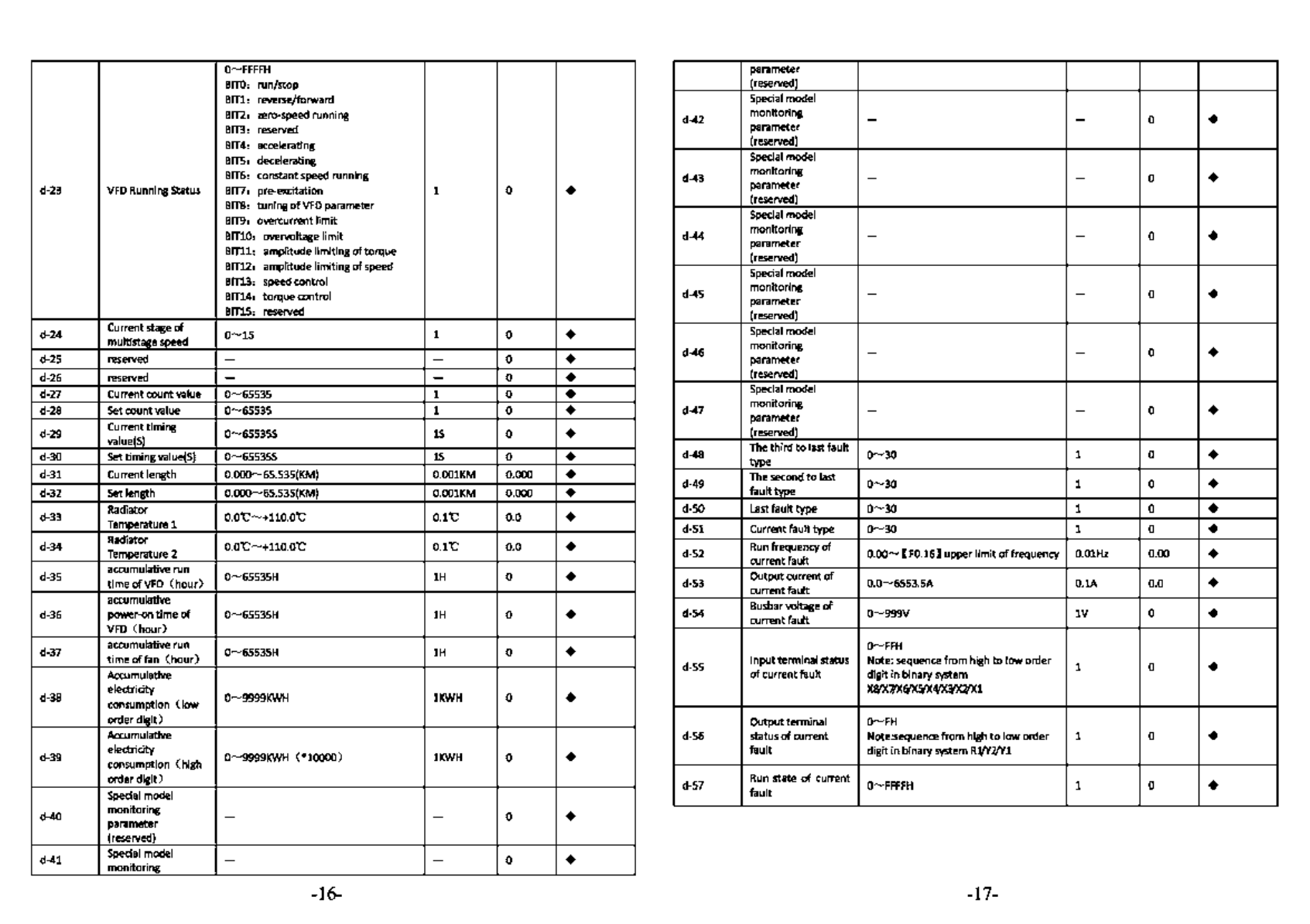
o~FFFFH
parameter
BITO:
run/stop (reseived)
Bill:
reverse/forward Special model
BIT2: zero-speed running
BIT3: reseived d-42 monitoring - - 0 •
parameter
BIT4: accelerating (reserved)
BITS,
decelerating Special model
BIT6: constant speed running
d-23
VFD
Running Status BIT7: pre-excitation 1 0 •
BITS:
tuning
of
VFD
parameter
BIT9: overcurrent
limit
BITlO,
overvoltage
limit
BITll:
amplitude limiting
of
torque
BIT12'
amplitude limiting
of
speed
BIT13: speed control
BIT14,
torquecontrol
Bins,
reseived
d-43 monitoring - - 0 •
parameter
(reserved)
Special model
d-44 monitoring - - 0 •
parameter
(reserved)
Special model
d-45 monitoring - - 0 •
parameter
(reserved)
d-24 Current stage
of
0~1s 1 0 •
multlstage speed
d-2S reseived - - 0 • Special model
d-46 monitoring - - 0 •
parameter
d-26 reseived - - 0 • (reserved)
d-27 Current count value
0-6SS3S
1 0 •
d-28
Set
count value
0-6SS3S
1 0 •
d-29 Current timing
0-6SS3S5
15
0 •
value(S)
d-30 Set timing value(S)
o~&ss3ss
15
0 •
Special model
d-47 monitoring - - 0 •
parameter
(reserved)
d-48 The third
to
lastfault
0-30
1 0 •
type
d-31 Current length 0.000-6S.535(KM}
O.OOlKM
0.000 •
d-32 Set length 0.000-6S.535(KM}
O.OOlKM
0.000 • d-49 The second
to
last
0-30
1 0 •
fault
type
d-33 Radiator
o.o'C-+110.o'C
O.l'C o.o •
Temperature 1 d-50
Last
fault type
0-30
1 0 •
d-Sl
Current fault type
0-30
1 0 •
d-34 Radiator
o.o'C-+110.o'C
O.l'C 0.0 •
Temperature 2
d-35 accumulative run
0-6S535H
lH 0 •
time
ofVFD
(hour)
d-52
Run
frequencyof
O.OO~
[ F0.16] upper
limit
of
frequency O.OlHz 0.00 •
current fault
d-53 Outputcurrent
of
o.o~65s3.SA
O.lA 0.0 •
current fault
accumulatlve
d-36 power-on
time
of
o~&ss3sH
lH 0 •
VFD
(hour)
d-54 Busbarvoltage
of
0-999V
lV 0 •
current fault
d-37 accumulative run
o~&S535H
lH 0 •
time
offan
(hour)
Accumulative
0......,FFH
d-S5 Inputterminal status Note: sequence from high
to
loworder 1 0 •
ofcurrentfault digit in binary system
d-38 electricity 0-9999KWH
lKWH
0 •
consumption Clow
X8/X7/Xf,fXS/X4fl2/X'1/X1
order
digit)
Outputterminal
O......,FH
Accumulative d-S6 status of current Note:sequence
from
high
to
low order 1 0 •
d-39 electricity
o~9999KWH
(•10000)
lKWH
0 •
consumption
(high
fault
digit in binary system
R'J/Y'1/Yl
order
digit)
Special model d-57
Run
state of current 0-FFFFH 1 0 •
fault
d-40 monitoring - - 0 •
parameter
(reseived)
d-41 Special model - - 0 •
monitoring
-16- -17-
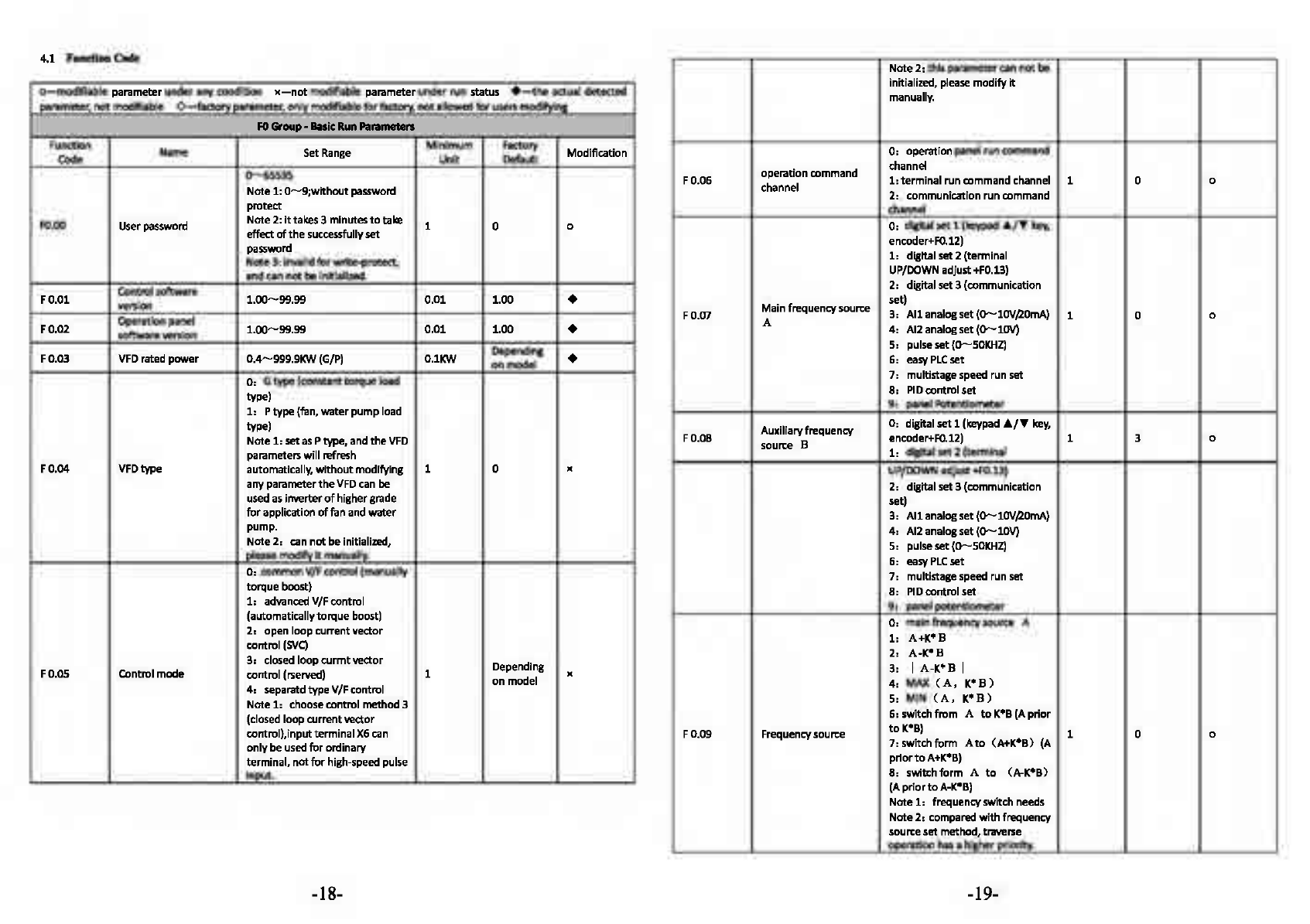
4.1
FunctionCode Note
2,
thisparametercan
not
be
o-modifiable
parameter under anycondition
x-not
modifiable parameter under
run
status •
the
actual detected
parameter,
not
modifiable
0-fattory
parameter,
only
modifiable
for
factory,
not
allowed
for
usersmodifying
initialized, please
modify
it
manually.
FO
Group-
Bllslc
RunParameters
Function
Minimum
Factory Modification
code
Name Set
Range
Unit Default
0-65535
Note
1:
0-9;withoot
password
O:
operation panel
run
command
operationcommand channel
F0.06
l:terminal
run
command channel 1 0 0
channel
2:
communication
run
command
protect
F0.00 User password
Note
2:
It
takes3 minutes
to
take 1 0 0
effectof
the
successfully
set
password
Note
3:
invalid
for
write-protect,
and can
not
be
initialized.
F0.01 Control software
1.00-99.99
0.01
1.00
•
version
F0.02 Operation panel
1.00-99.99
0.01
1.00
•
softwareversion
VFD rated
power
0.4-999.9KW
(G/P) O.lKW Depending •
F0.03
on
model
O: G
type
(constant
torque
load
type)
1:
P
type
(fan, water
pump
load
channel
O:
digital
set
1 (keypad
•I~
key,
encoder+F0.12)
1:
digitalset2 (terminal
UP/DOWN adjust+F0.13)
2: digitalset3 (communication
Mainfrequencysource set)
FO.Q7
3: Al
lanalogset(0-10V/20mA)
1 0 0
A
4:
Al2 analogset
(O-lOV)
5:
pulseset(O-SOKHZ)
6:
east
PLC
set
7:
multistage speed run set
8:
PIO
control set
9:
panel Potentiometer
type)
Note
1:
set
as
Ptype,
and
the
VFD
parameters
will
refresh
Auxiliaryfrequency
0:
digital
set
1 (keypad
•t~
key,
F0.08 encoder+F0.12) 1 3 0
source B
1:
digitalset2 (terminal
F0.04 VFDtype automatlcally,
without
modifying 1 0 x UP/DOWN adjust+F0.13)
any parameter
the
VFD
can
be
usedas inverter
of
highergrade
for
application
of
fan and
water
2: digitalset3 (communication
set)
3:
Allanalogset(0-10V/20mA}
pump.
Note
2:
can
not
beinitialized,
please modify
it
manually.
O: common V/Fcontrol (manually
torque
boost}
1:
advanced V/Fcontrol
(automatically
torque
boost)
2:
openloopcurrentvector
control
(SVC)
3:
closed
loop
curmt
vector Depending
Controlmode control (rserved) 1 x
F0.05
on
model
4:
separatd
type
V/Fcontrol
Note
1:
choosecontrol method 3
(closed loopcurrentvector
control),inputterminalX6can
only
be
used
for
ordinary
terminal,
not
for
high-speed pulse
input.
4:
Al2 analogset
(O-lOV)
5: pulse
set
(0-SOKHZ)
6:
east
PLC
set
7:
multistage speed run set
8:
PIO
control set
g, panel potentiometer
0:
main frequencysource A
1:
A+K*B
2:
A-K*B
3:
I
A-K*B
I
4:
MAX
CA,
K*B)
5: MIN
(A,
K*B)
6:
switch
from
A
to
K*B
(A
prior
F0.09 Frequencysource
to
K*B) 1 0 0
7:
switch
form
A
to
(A+K*B)
(A
prior
to
A+K*B)
8:
switch
form
A
to
(A-K*B)
(A
prior
to
A·K*B)
Note
1:
frequencyswitch needs
Note
2:
compared
with
frequency
sourceset method,traverse
operation
has
a higherpriority.
-18- -19-

LED
ones
digit:
power
down
storage
F0.10
Digital
set
1 control
0:
storage
1
000
0
1:
not
storage
0:
start
at
start
frequency
F
1.00
Start
mode
1:
DC
braking+
start
at
start
1 0 x
frequency
2:
start
with
speed
tracking
LED
tens
digit: hold
when
stop
F
1.01
Stan
frequency
0.00-50.00Hz
O.OlHz 1
.00
0
0:
hold
1:
not
hold F
1.02
Start
frequency
hold
0.0-100.0s
O.ls
0.0
0
time
LED
hundred
digit: J../'f key,
F
0.11
Digital
set
2 control UP/DOWN
frequency
1
000
0
0:
invalid
1:
valid
F
1.03
DC
brake
current
at
0.0-150.o%•rated
current
of
0.1% 0.0% 0
startup
motor
Fl.04
DC
brake
time
at
0.0-100.0s
O.ls
0.0
startup
0
LED
thousands
digit:
reserved
F
0.12
Frequency
source
O.OOHz-
[F0.16]
upper
limit
of
0.01Hz
50.00
0
digital
setting
1
frequency
F
0.13
Frequency
source
O.OOHz-
[F0.16]
upper
llmlt
of
0.01Hz
50.00
0
dlgttal
setting
2
frequency
Auxiliary
frequency
F
1.05
Accelerating
and
0:
linearAce/Dec
mode
1 0 x
decelerating
mode
1:
S curve Ace/Dec
mode
F
1.06
Time
ratio
of
initial
10.0-so.0%
0.1% 20.0%
segment
in
Scurve 0
F
1.07
T
ime
ratio
of
ending
10.0-50.0%
0.1% 20.0% 0
segment
in
Scurve
F0.14
source
weight
0.01-10.00
0.01
1.00
0
coefficientK
setting
Low
frequency
range:
MAX
Fl.OS
Stop
mode
0:
Decelerate
to
stop
1 0 x
1:
coasttostop
Maximum
output
{50.00,
[F0.16]
} -
300.00
F
0.15
0.01Hz
50.00
x
frequency
High
frequency
range:
MAX
{50.00,
[F0.16]
} -
3000.0
F
0.16
Upper
limitfrequency
[F0.17]
-
[F0.15]
0.01Hz
50.00
x
Fl.09
Frequencythreshold of
0.00-
[F0.16]
upper
limit 0.01Hz
0.00
0
DC
brake
frequency
F
1.10
DC
brake
delay
time
0.0-100.0s
O.ls
0.0
0
F
1.11
DC
brake
current
0.0-150.0%*rated
current
of
0.1% 0.0% 0
motor
F
0.17
Lowerlimitfrequency O.OOHz-
[F0.16]
0.01Hz
0.00
x F
1.12
DC
brake
time
at
stop
0.0-100.0s
O.ls
0.0
0
0:
low
frequency
mode
(0.00-
300.00Hz) F
1.13
Acctlme2
0.1
Depending 0
on
model
F
0.18
Frequency
output
1:
high
frequency
mode
(O.O
-1 0 x
mode
3000
.0Hz)
Note: high
frequency
mode
is
onlyeffective
to
VF
control
F
0.19
Acceleration
time
1
0.1
-3600.0s
0.ls
Depending
on
model
0
0.4
-4.0KW 7.55
5.5
-30.0KW
15.0s
F0.20
Deceleration
time
1
37.0
-132.0KW 30.0s
0.ls
Depending 0
160.0-
630.0KW 60.0s
on
model
Fl.14
Dectime2
0.1
Depending 0
0.1
-
3600.0s
on
model
F
1.15
Acctinme
3
0.4
-4.0KW
7.5s
0.1
Depending 0
on
model
5.5
-30.0KW 15.0s Depending
F
1.16
Dectime3
37.0
-132.0KW 40.0s
0.1
on
model 0
160.0-
630.0KW 60.0s Depending
F
1.17
Acctimne4
0.1
on
model 0
F
1.18
Dectime4
0.1
Depending 0
on
model
0:
forward
F
0.21
Runningdirection
1:
reverse 1 0 x
2:
prevent
reversing
F
1.19
Ace/Dec
time
unit
0:
second
1:
min
u
te
2:
O.ls 1 0 0
F
1.20
Frequencysetting
of
0.00-
[F0.16]
upper
limit O.OlHz
5.00
0
forward
jog
operation
frequency
1.0-16.0KHz
D.4-4.0KW
6.0KHz F
1.21
Frequency
setting
of
o.oo-
[F0.16]
upper
limit 0.01Hz
5.00
0
reverse
jog
operation
frequency
1.0-16.0KHz
5.5-30KW
4.5KHz Depending
F
0.22
Carrier
frequency
1.0-16.0KHz
O.lKHz
on
model
0
37-132KW
3.0KHz
1.0-10.0KHz
0.1
-
3600.0s
Depending
F
1.22
Jog
Ace
time
0.4
-4.0KW
7.5s
O.ls
on
model 0
5.5
-30.0KW 15.0s
37.0
-132.0KW 40.0s Depending
F
1.23
Jog
Dec
time
160.0-
630.0KW
60
.
0s
O.ls
on
model 0
160-630KW
1.SKHz
1.0-5.0KHz
Fl
Group
-Auldllary
Operatlns
,.........,..
F
1.24
Jog interval
time
0.0
-100.0s
O.ls
0
.1
0
F
1.25
Hopping
freq.l
0.00-upper
limitfreq. O.OlHz
0.00
0
F
1.26
Hopping
freq.1
range
0.00-upper
limitfreq. 0.01Hz
0.00
0
F
1.27
Hoppingfreq.2
0.00-upper
limitfreq. O.OlHz
0.00
0
-20- -21-

F1.28 Hoppingfreq.2 range
0.00-upper
limitfreq.
O.OlHz
0.00
0
F1.29 Hoppingfreq.3
0.00-upper
limitfreq.
O.OlHz
0.00
0 F2.10 No-load current
of
O.Ol
-655.35A
O.OlA
Depending
asvnchronous
motor
on
model
JC
F1.30 Hoppingfre.3 range
0.00-upper
limitfreq.
O.OlHz
0.00
0
0:
run
at
lower limit freq. F
2.11-
Reserved 0 •
F2.15 - -
Action
when
set
freq.
1:
run
at
zerofreq. after delay
F1.31 is lower
than
lower
time
(start
without
delay)
1 0 "
0:
no
action
limitfreq.
2:
stop
afterdelay
time
(start
without delay) F2.16 Motortuning
1:
statictuning 1 0
JC
2:
no-load complete tuning
Delay time
of
stopping
3:
on-load complete tuning
F1.32
when
freq. is lower
o.0-3600.0s
0.1
10.0
0
than
limit(simple
0.00-10.oos
0.4-4.0KW
O.OSs
sleep)
F1.33 Zero freq. brake
0.0-150.0%*rated
current
of
0.1 o.o
)(
current
motor
F2.17 pre-excitation time
of
S.5-30KW
O.lOs O.
Ols
Depending
JC
asynchronous
motor
37-132KW
0.30s
on
model
160-630KW
a.sos
F1.34 FWD/Rf)! transition
0.0-100.0s
O.ls 0.0 0
time
note
: invalid for
VF
control
FJ
Group
-
Reserved
Pll'llmeterl
F1.35 FWD/Rf)! switch mode
0:
over
zerofreq. switch 1 0 "
1:
over
start
freq. switch
Standbydeceleration
f.tGroup·
Speed
Loop,
Torque
and
Flux
COntrol
P1111met1rs
F4.00
Speed loop
(ASRl)
0.000-6.000
0.001 1.000 0
proportional gain
F1.36
time
when
emergency
0.1-3600.0s
O.ls 1.0 0
brake F4.01 Speed loop
(ASRl)
0.000-32.000s
O.OOls 1.000 0
integral
time
P2Group.
Motor
Parameters
F4.02 ASRl filter time
0.000-0.lOOs
O.OOls
0.000 0
constant
0:
AC
asynchronous
motor
1:
PMSM
(reserved)
Note
1:
onlyclosed-loopvector
Fl.00
Motor
type control isacceptable
by
1 0 "
synchronous machine
at
present
Note
2:
this
parameter
can
not
be
initialized, please modify it
manually.
F2.01 Motor's rated power
0.4-999.9KW
O.lKW
Depending "
on
model
F4.03 Switch low point freq. O.OOHz-
[F4.07]
O.OlHz 5.00 0
F4.04
Speed loop
(ASR2)
0.000-6.000
0.001 1.500 0
proportional gain
F4.05 Speed loop
(ASR2)
0.000-32.000s
O.OOls
0.500 0
Integral
time
F4.06
ASR2
filter time
0.000-0.lOOs
0.001s 0.000 0
constant
F4.07
Switch high pointfreq.
[F4.03]-[F0.16]
upper
limit
O.OlHz
10.00 0
freq.
Fl.02
Motor's ratedfreq. 0.01Hz-[F'-0.15]maximum freq. 0.01Hz 50.00 "
F2.03 Motor's rated
speed
0-60000RPM
lRPM Depending "
on
model
F2.04
Motor's ratedvoltage
0-999V
lV
Depending "
on
model
Fl.OS Motor's ratedcurrent
0.1-6553.5A
O.lA Depending "
on
model
F2.06
Stator
resistance of
0.001-20.0000
0.0010
Depending
asynchronous
motor
on
model "
F2.07 Rotor resistance
of
0.001-20.0000
0.0010
Depending
asynchronous
motor
on
model
JC
Stator
and
rotor Depending
F2.08
Inductance of
0.1-6553.SmH
O.lmH
JC
asynchronous
motor
on
model
Vector control of
positive slip 50.0% -200.0%*rated slip
F4.08
compensation factor frequency 0.1% 100.0% 0
(electromotion state)
Vector control of
negative slip 50.0% -200.0%*rated slip
F4.09
compensation factor frequency 0.
1%
100.0% 0
(brakingstate)
0: speed
F4.10 Speed
and
torque
1:
torque
1 0
control
)(
2: valid conditionally(terminal
switch)
F4.11 Speed
and
torque
0.01-1.00s
O.Ols 0.05
switchingdelay
)(
Stator
and
rotor Depending
F2.09
mutual inductance
of
0.1-6553.SmH
O.lmH
JC
asynchronous
motor
on
model
0:
keypad set
F4.12 Torque command
1:
All
1 0 0
2:
All
3:communication
set
-22- -23-

F4.13
Torque
set
by
keypad -200.0%-200.0%*rated current 0.1% 0.0%
of
motor 0
Speed limit channel 1
0:
keypad
set
1
F4.24
Torque detection
time
o.0~10.0s
O.ls 0.0 x
F4.25 Cut off freq.
of
statlc
0.00-300.00Hz
O.OlHz
10.00 0
friction coefficient
F4.14
of
torquecontrol mode
1:
All
1 0 0
(forward}
2:
Al2
F4.26 Static friction
0.0-200.0
0.1 0.0
coefficient
set
0
speed
limit channel 1
0:
keypad
set
2
F4.15
of
torque
control mode
1:
All
1 0 0
(reverse)
2:
Al2
F4.27
Hold
time
of static
0.00-600.00s
O.Ols 0.00
friction coefficient x
F5
Group-
VF
Control
,_.IMhnl
0:
linearcurve
F4.16
Keypad limit
speed
1
0.0-100.0%*[F0.15]maximum
0.1% 100.0% 0
freq.
1:
decreasing
torque
curve
1(
1.3
power)
F4.17 Keypad llmit
speed
2
0.0-100.0%*[F0.15]maximum
0.1% 100.0% 0
freq.
f 4.18 Torque risetime
0.0-10.os
0.15
0.1
0
2: decreasing
torque
curve
2(
1.5
FS.00
V/F
curve
set
power)
1 0
)(
3:decreasing
torque
curve 3(1.7
F4.19 Torque decline
time
0.0-10.os
0.15
0.1
0
power)
G
type:
o.0%-200.0%*rated
4:
squarecurve
F4.20
Electromotion torque current
of
motor 180.0% 0.1% Depending
limit ofvectormode P
type:
o.0%-200.0%*rated
on model 0 5: user
set
V/F
curve
(determined
by
F5.01-FS.06)
current
of
motor 120.0% F5.01
V/F
frequency
Fl
O.OO-F2 (frequencyvalue) 0.01Hz 12.50
)(
G
type:
0.0%~200.0%*rated
f 4.21 braking torque limit
of
current
of
motor 180.0% 0.1% Depending
vector mode P
type:
0.0%-200.0%*rated
on model 0
F5.02
V/F
voltage
Vl
O.O-V2{voltage value) 0.1% 25.0%
)(
F5.03
V/F
frequency
F2
F1-F3
(frequencyvalue)
O.OlHz
25.00 x
current
of
motor 120.0%
0:
detect
Invalid
F5.04
V/F
voltage
V2
V1-V3
(voltagevalue) 0.1% 50.0% x
1:
keep running after over
torque
detected duringconstant FS.05
V/F
frequency
F3
Freq. Value
F2-
[F2.02)
rated
O.OlHz
37.50
)(
frea. of motor
speed
2:
keep runnlng after over F5.06
V/F
voltage
V3
Voltage value
V2-100.0%*
0.1% 75.0%
)(
[ F2.04) rated voltage ofmotor
torquedetected duringrunning
3:
cut
off
output
afterover
torque
detected duringconstant
speed
4:
cut
off
output
afterover
Torque detection
torque
detected duringrunning
F4.22
action
5:
keep runnlng after
torque
1 0
)(
shortage detectedduring
constantspeed
6:
keep running after
torque
shortage detectedduring
running
7:
cut
off
output
after
torque
shortage detectedduring
constantspeed
8:
cut
off
output
after
torque
shortage detectedduring
running
G
type:
o.0%-200.0%*rated
F4.23
Torque detection level current
of
motor 150.0% 0.1% Depending
Ptype:
o.0%-200.0%*rated
on model x
current
of
motor 110.0%
F5.07 Torque boostsetting
0.0-30.0%
*ratedvoltage
of
0.1% Depending x
motor
[F2.04)
on
model
F5.08 Torque boostcutoff
0.00-rated
freq.
of
motor 0.01Hz 50.00 x
point
V/F
control slip
0.0-200.0%*rated
slip
FS.09 frequency note: default
as
100.0%ln 0.1% 0.0% 0
compensation advanced
VF
control mode
V/F
control slip
FS.10 compensation filtering
1-10
1 3 0
coefficients
V/F
control torque
F5.11 compensation filtering
0-10
1 0 0
coefficients
0:
VF
halfseparated mode,
voltageopen-loop
output
1:
VF
halfseparated mode,
voltageclosed-loop
output
2:
VF
completeseparated
FS.12 Separated type
V/F
mode, voltage open-loop
output
1 0 x
control 3:
VF
completeseparated
mode,
voltage closed-loop
output
Note
1:
when choose
VF
separatedcontrol, please
dose
the
dead-time compensation
-24- -25-

function
0.0-100.0
%•rated voltage
of
Note
2:
halfseparatedoonceptis
motor
based
on
that
during start-up note: thisvoltage represents
the
the
frequency
and
voltage
of
VFO
remains
the
VVVF
relation,
but
get
separatedafter
the
Limit
voltage
of
voltage
output
voltage
of
VFD,
and
F5.24 feedback disconnection reasonablesetting
of
tilts 0.1% 80.0% 0
parametercould prevent
reaching
of
set
frequency machinedamage resulting from
0:
digital setting
F5.13 Voltage setting cllannel
l:
All
1 0 0
2:
A12
voltageovershoot
at
disconnection moment.
F&
Group-AMIOI
Qu.ntlty
Mid
PUIA
Input
1nd
Output.._,...,
0:
speedcommand
(output
voltagefeedback
0:
All
l:
Al2
F5.14 metllod
of
voltage 1 0
..
close-loop
output
note: onlyvalid for
dosed
loop
output
mode
freq., -100.0%-100.0%)
All
Inputcorresponding
1:
torquecommand
(output
F6.00 pllyslcal quantity
torque,
-200.0%-200.0%) 1 0
..
2: voltage oommand
(output
0.0-200.0%*rated
voltage of
motor
F5.15 Output voltage
of
note: in open loop
output
mode, 0.1% 100.0% 0
digital setting
the
maximum
output
voltage
Is
100.0%
of
rated voltage
of
motor
Deviation limit
of
o.o -5.0 %
•rated
voltage
of
F5.16 voltageclosedloop 0.1% 2.0%
..
re11ulation
motor
voltage,
0.0%-200.0%
•rated
voltage
of
motor)
F6.01
All
input lower-limit
O.OOV,tl.OOmA-
O.OlV
0.
00
0
10.oovao.oomA
All
lowerllmlt -200.
0%-200.0%
F6.02 correspondingpllyslcal note: range is relevant
to
P6.00 0.1% 0.0% 0
quantity
set
F6.03
All
input upperlimit
O.OOV,tl.OOmA-
O.OlV
10.00 0
10.oovao.oomA
0.0-100.0%
*ratedvoltage
of
F5.17
VF
curve max. voltage motor 0.1% 80.0%
of
halfseparation mode note:
this
voltage represents
..
All
upper limit -200.0%-200.0%
F6.04 correspondingpllysical
note:
range is relevant
to
P6.00 0.1% 100.0% 0
quantitysetting
output
voltageofVFD
controller adjustment F6.05
All
Inputsmoothing
o.oos-10.oos
0.015 0.
05
0
time
F5.18 cycle
of
voltage closed
0.01-10.oos
O.Ols
0.10
..
0:
speedcommand
(output
loop
output
freq., -100.0%-100.0%)
F5.19 Voltage rising
time
0.1-3600.0s
O.ls
10.0
0
note: tllis parameter
is
onlyvalid
F5.20 Voltage declining
time
for
open
loop
output
mode
of
O.ls
10.0
0
completeseparatedvoltage
Al2
input corresponding
1:
torquecommand
(output
F6.06
torque,
-200.0%-200.0%) 1 0
..
pllysical quantity 2: voltage command
(output
voltage,
0.0%-200.0%
•rated
0:
alarm and keep running with voltage
of
motor)
the
voltage
of
disconnection F6.07
Al2
Input lower llmlt O.OOV-10.0CN
O.OlV
0.
00
0
Voltage feedback
moment
F5.21 disconnection
1:
alarm and keep running with 1 0
..
treatment
decreased voltage ofamplitude
llmltlng value
2:
protection action
and
free
stop
Detectionvalue
of
0.0-100.0%*rated voltage
of
F5.22 voltagefeedback 0.1% 2.0% 0
disconnection motor
Detectiontime of
F5.23 voltagefeedback
0.0-100.0s
O.ls
10.0
0
disoonnection
Al2
lowerlimit -200.0%-200.0%
F6.08 correspondingpllysical
note:
range is relevant
to
P6.00 0.1% 0.0% 0
quantitysetting
F6.09
Al2
input upperlimit
o.oov-10.oov
0.01V 10.00 0
Al2
upper limit -200.0%-200.0%
F6.10 correspondingpllysical note: range
Is
relevant
to
P6.00 0.1% 100.0% 0
quantitysetting
F6.11
Al2
Inputfllterlng
time
o.oos-10.oos
0.015 0.
05
0
F6.12 Error limit
of
analog O.OOV-10.0CN
O.OlV
0.10 0
Input
F6.13 Threshold
of
zerofreq. Zerofreq. hysteresis-50.00Hz 0.01Hz 0.00 0
operation
F6.14 zero freq. hysteresis
0.00-zero
freq. thresholdvalue 0.01Hz 0.00 0
-26- -27-
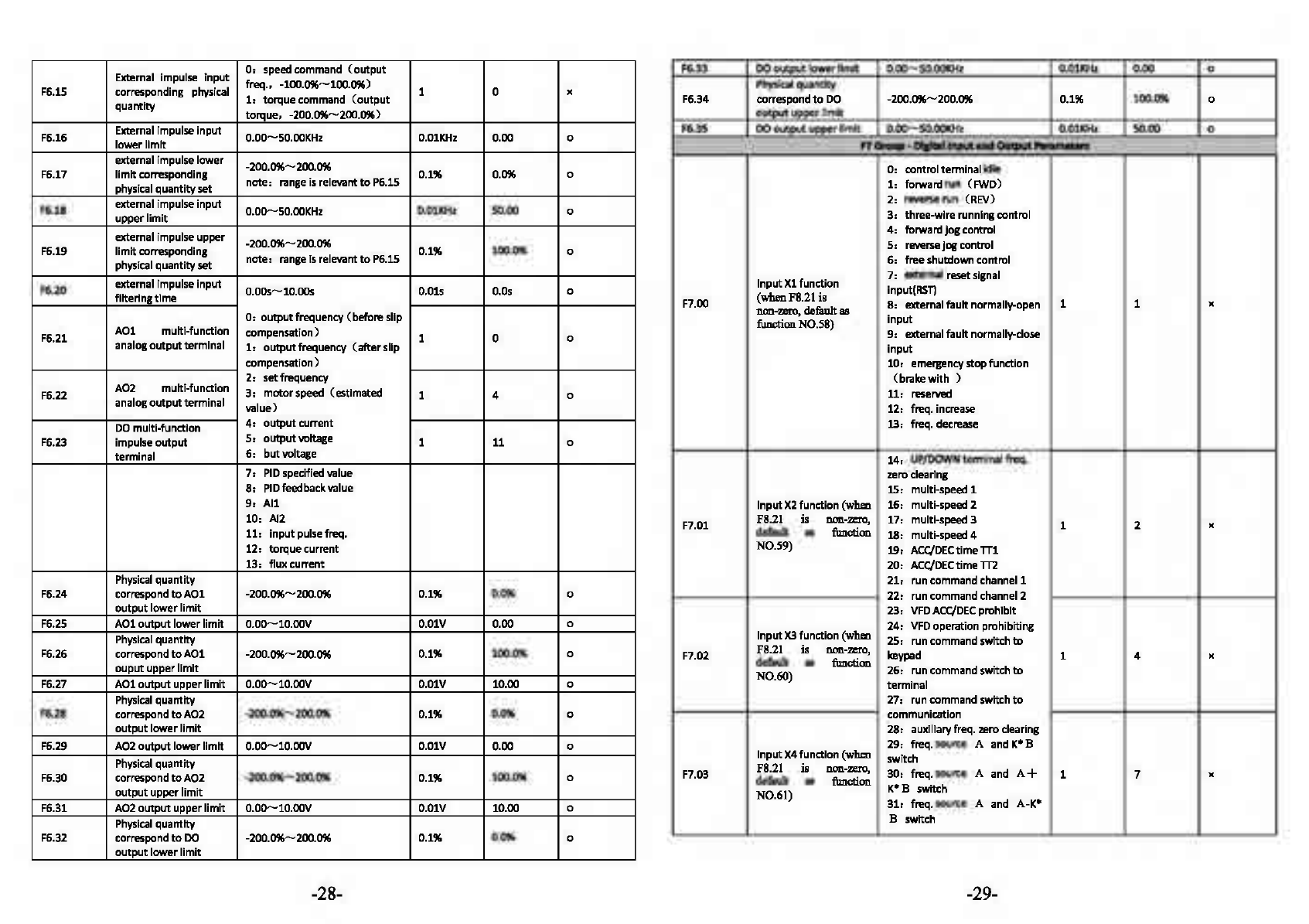
External impulse input
0:
speed command
(output
freq., -100.0%-100.0%)
F6.15 corresponding physical
1:
torquecommand
(output
1 0
)(
quantity torque, -200.0%-200.0%)
F6.33
DO
outputlower
limit
0.00-50.00KHz
O.OlKHz
0.00 0
Physical
quantity
F6.34 correspond
to
DO
-200.0%-200.0% 0.1% 100.0% 0
output
upper
limit
F6.16 External impulse input o.oo-50.00KHz
O.OlKHz
0.00 0
lowerllmlt
F6.35
DO
outputupper
limit
0.00-50.00KHz
O.OlKHz
50.00 0
F1
a-.
-
Df&bl
Input
•nd
Output...,.metmn
external impulse lower -200.0%-200.0%
F6.17
limit
corresponding note: rangeis relevant
to
P6.15 0.1% 0.0% 0
physical quantity
set
F6.18 external impulse input 0.00-50.00KHz
0.01KHz
50.00 0
upper
limit
0: controltenminal idle
1:
forward run
(FWD)
2: reverse run (REV)
3: three-wirerunningcontrol
external impulse upper -200.0%-200.0%
F6.19
limit
corresponding note: range
Is
relevant
to
P6.15 0.1% 100.0% 0
physical quantity
set
F6.20 external impulse input
o.oos-10.00s
O.Ols
O.Os
0
flltertngtlme
0:
outputfrequency (beforeslip
F6.21
AOl
multi-function compensation) 1 0 0
analogoutput terminal
1:
outputfrequency
(after
slip
4:
forward
jog
control
5:
reverse
jog
control
6: freeshutdown control
Input
Xl
function 7:
e>Cternal
resetslgnal
input(RST)
F7.00 (wbenFS.21is 8:
e>eternal
fault normally-open 1 1 x
llO'll-zero,
default
811
function N0.58) input
9:
e>Cternal
fault normally-close
input
compensation) 10: emergencystopfunction
2:
setfrequency
F6.22
A02
multi-function
3:
motorspeed (estimated 1 4
analogoutput terminal 0
value)
(brakewith
)
11:
reserved
12: freq. increase
DO
multl-functlon
4:
output
current
13:
freq. decrease
F6.23 impulseoutput
5:
output
voltage 1
11
0
terminal
6:
butvoltage 14: UP/DOWNtenminal freq.
7:
PIO
specified value
zero
clearlng
8:
PIO
feedbackvalue 15: multi-speed 1
9:
All
Input
X2
function (when 16: multi-speed 2
10: Al2
11:
input
pulsefreq.
12: torquecurrent
F7.01
FS.21
is
non-zero,
17: multi-speed 3 1 2 x
default
as
function
18: multi-speed 4
N0.59) 19:
ACC/DEC
time
TTl
13: fluxcurrent 20:
ACC/DEC
time
TT2
Physical
quantity 21: run command channel 1
F6.24 correspond
to
AOl
-200.0%-200.0% 0.1% 0.0% 0 22: run command channel 2
output
lower
limit
23:
VFDACC/DEC
prohibit
F6.25
AOl
outputlower limit
0.00-10.oov
O.OlV 0.00 0
Physical
quantity
F6.26 correspond
to
AOl
-200.0%-200.0% 0.1% 100.0% 0
ouput
upperlimit
F6.27
AOl
outputupper
limit
0.00-10.oov
O.OlV 10.00 0
24:
VFD
operation prohibiting
Input
X3
function (when 25: run command switch
to
F7.02
FS.21
is
non-zero,
keypad 1 4 x
default
811
function
26: run command switch
to
N0.60) termlnal
Physical
quantity 27: r
un
command switch
to
F6.28 correspond
to
A02
-200.0%-200.0% 0.1% 0.0% 0 communication
output
lower
limit
28: auxlllaryfreq. zero clearing
F6.29
A02
outputlower llmlt
0.00-10.oov
O.OlV 0.00 0
Physical
quantity
F6.30 correspond
to
A02
-200.0%-200.0% 0.1% 100.0% 0
outputupper
limit
F6.31
A02
outputupper
limit
0.00-10.oov
O.OlV 10.00 0
Physical
quantity
Input
X4
function (when 29: freq. source A and K*B
switch
F7.03
FS.21
is
non-zero,
30: freq. source A and
A+
1 7 x
default
as
function
K*B
switch
N0.61) 31: freq. source A and
A-K*
B switch
F6.32 correspond
to
DO
-200.0%-200.0% 0.1% 0.0% 0
output
lower
limit
-28- -29-

32:
reserved
0-FFH
33:
PIO
control input O
is
positive logic, i.e. terminal
Xi
34:
PIO
control pause
is
enabled when
it
connects with
Input
XS
function (when 35, start traverse operation
FS.21 is
non-zero,
36: pause traverse operation
F7.04 default
as
function 37, traverse status reset 1 8 x
N0.62) 38,
PLC
control
input
39,
PLC
pause
40,
PLC
reset
Effective logic setting
of
common terminal and disabled
F7.10
Inputterminal
(Xl
.......
if
disconnected. 1 00 x
XS}
1
is
negative logic, i.e. terminal
Xi
is
disabled when
it
connects
with
common terminal and
enabled when disconnected.
41: clear
the
counter
to
zero
o,
two-wirecontrol mode 1
42,
input
signal
to
trigger
the
counter
43:
timing
triggering
input
F7.11
FWD/REV
terminal 1, two-wirecontrol mode 2
control mode 2, three-wire control mode 1 1 0 x
3:
three-wire control mode2
44:
timing
clearing
input
45:
input
external impulse UP/OOWN terminal
Input
X6
function frequency
(only
valid
for
X6)
46: clear
the
length information
( high-speed Impulse 47: input
the
signal of length
F7.05
input, when F8.21
is
(onlyvalidforX6)
1 0 x
non-zero, default
as
48: switch speed and torque
function
N0.63)
control
F7.12
frequency modifying
0.01-50.00Hl/5
O.OlHl/5 1.00 0
rate
F7.13 reserved 0 •
F7.14
Yl
output
delay
time
0.0.-....100.os
0.15 0.0 x
F7.15
Y2
output
delay
time
0.0.-....100.os
0.15 0.0 x
49: prohibittorque control
F7.16
Rl
output
delay time
0.0.-....100.os
0.15 0.0 x
50""55: reserved
55-57:
reserved
F7.17
R2
output
delay
time
0.0.-....100.os
0.15 0.0
(reserved} x
58: start/stop
o,
no
output
59, running allowed
50,
interiockl
61: lnteriock2
52, intertock3
63:
PFC
start/stop
64, A frequencyswitch
Band
1,
VFD
forward running
Open collector
output
2,
VFD
reverse running
F7.18
termlnalYl
3, fault
output
1 0 x
4:
freq./speed level detection
signal (FDTl)
5: freq./speed level detection
signal
(FDT2)
run
65"'99: reserved
F7.06
Input
X7
function 1 45 x
6: freq./speed arrival signal
F7.19 Open collector
output
(FAR}
termlnalY2
7:
VFD
zero-speed running 1 0 x
8:
upper
limit
arrival
of
output
freq.
9:
lower
limit
arrival
of
output
freq.
10: lower
limt
arrival ofpreset
freq. duringrunning
Programmable relay
Rl
11: pre-alarm signal
of
overload
F7.20
12: counterdetection signal 1 3
output
x
output
13: counerdetection reset signal
F7.07 reserved - - 0 •
output
F7.08
Digital filtering times
1-10
1:
2M5 unit
of
scanning
time
1 5 0 14: driverready
Termlnal function
0:
terminal operation command
F7.09
detection when power invalid when poweron 1 0
1:
terminal operation command 0
on
valid when poweron
-30- -31-

15:
one
cycle finished
of
programmable
MS
running
16:
stage finished of
pogrammable MSrunning
17:
upperand
lower
limit
of
traversefreq.
F7.27
FDT2
detection method
0:
speed setvalue 1 0 0
1: speed detected value
F7.28
FDT21evel
O.OOHz-
[F0.16]
upperlimit
O.OlHz 25.00 0
freq.
F7.29
FDT21ag
0.0-100.0%•
[F7.28]
0.1% 4.0% 0
18:
currentlimitingaction
19:
stall overvoltage
20:
low
voltage lock-up
21:
dormancystilte
22:
VFD
alarmsignal
(PID
0:
stopcounting,stop
output
Counting value arrival 1:
stop
counting, resume
output
1 3 x
F7.30 processing
2:
cyclecount, stop
output
3:
cyclecount. resume
output
disconnection,
RS485
Programmablerelay
R2
communication failure, panel
F7.21 communicationfailure,
EEPROM
1 0
)(
output
read-writefailure, encoder
0:
alwayscount since power
on
F7.31 Counting
start
1: countinoperationstatus, 1 1
lC
condition stop countinginstop status
F7.32 Counterreset value
[F7.33]
-65535
1 0 0
disconnection,etc.)
23:
All>Al2
Counter detection
0-
[F7.32]
1 0 0F7.33 value
24:
preset lengtharrival
25:
presetoperation
time
out
0:
stop
timi
n
g,
stop
output
26:
dynamicbrakingaction
27:
DC
braking action 1: stoptiming, resume
output
1 3 x
F7.34
time
out
processing
2:
cycletiming. stop
output
28:
flux
brakingaction
3:
cycletiming. resume
output
29:
torquelimiting
30:
overtorquesignal
31:
auxiliary
motor
1
32:
auxiliary
motor
2
0:
timingstarts sincepower
on
F7.35 Timingstartcondition
1:
timingstarts inoperation 1 1 x
status, and stops instop
status
33:
accumulilted operiltion
time
out
34-49:
segment
of
MS
or
simple
PLC
operation
50:
runningIndicationslgnal
F7.36 Timingsetting
0-655355
ls
0 0
F7.37
Yl
turn
off delay
time
0.0-100.os
O.ls
0.0
x
F7.38
Y2
turn
off delay
time
0.0-100.os
O.ls
o.o
x
F7.39
Rl
turn
offdelay
time
0.0-100.0s
O.ls
0.0
x
F7.40
R2
turn
off
delay
time
0.0-100.0s
O.ls
0.0
x
51:
temperature arrival
indieiltion
Fl
Group-PIDCanlrol
Pll•1..-S
52-99:
reserved
0-3H
0:
positive loglc,I.e.termlnal
YI
PIO
operation input
0:
auto
F8.00 1: manually
input
viadefined 1 0 x
mode multi-functionterminal
isenabled when
it
connects
Logic setting
of
output
with
commonterminal, and
F7.22 disabled
if
disconnected. 1 0
)(
terminal
(Y1-Y2)
1:
negative logic,i.e.terminal
Yi
0:
digital setting
1:
All
F8.01
PIO
inputchannel
2:
Al2 1 0 0
isdisabled when
it
connects 3: pulsesetting
with
commonterminal, and
4:
R5485
communication
enabled
if
disconnected.
F7.23 Freq. arrival
0.0-100.0%'(F0.15]max.
freq. 0.1% 100.0% 0
detectionrange
(FAR)
F8.02 Dlgltal reference Input
0.0-100.0%
0.1% 50.0% 0
settim:r:
F7.24
FDTl
detection method
0:
speed setvalue 1 0 0
1:
speed detected value
F7.25
FDTl
lever O.OOHz-
[F0.16]
upper
limit
0.01Hz 50.00 0
freq.
F7.26
FDTllag
0.0-100.0%*
[F7.25]
0.1% 2.0% 0
-32- -33-

0:
All
0.0-200.0%
1:
Al2
2:
Al1+Al2
F8.03
PIO
feedback channel
3:
All-Al
2 1 0
4:
MAX
{All,
Al2}
0
Thresholdvalue
of
Note:
this
thresholdvalue
is
the
FB.15
sleeping percentage
of
given pressure, 0.1% 100.0% 0
and
It
Is onlyvalld
for
the
first
sleep mode.
5:
MIN
{All,
Al2}
6:
pulse setting
7:
RS485
communication
Thresholdvalue
of
0.0-200.0%
FB.16
awaking
Note:
this
threshold value
is
the
0.1% 90.0% 0
percentage
of
given pressure.
LED
one's place:
PIO
sign
FS.17
Delay
time
ofsleep
0.0-3600.0s
0.lS
100.0 0
0:
positive
1:
negative
FB.18
Delay
time
ofawaking
0.0-3600.0s
O.lS
5.0
0
LED
ten's place: proportion
regulation (reserved
I
FS.19
Delay
time
ofadding
0.0-3600.0s
O.lS 10.0 0
pump
O:
integralregulation
of
constant
proportion
FB.20
Delay
time
of
reducing
0.0-3600.0s
O.
lS
10.0 0
pump
1:
Integralregulatlon
of
auto
changing proportion
F8.04
PIO
controlleradvanced
LED
hundred'splace: Integral 1
setting regulation 000 "
Watersupplyenabling
O:
disabled
(FB.21-FS.
24
not
FB.21
supported by
1:
PFC
enabled 1 0
)(
hardware) 2:
SPFC
enabled
0:
stop integral regulation
when
the
frequencyreaches
the
upper
FB.22
Delay
time
of
terminal
0.0-6000.0s
O.ls
0.1
disconnectand connect 0
or
lower
limits
1:
contlnue
the
Integral
FS.23
Polling
time
0.0-6000.0s
O.lh
48.0 0
regulation when
the
frequency
reaches
the
upper
or
lower
FB.24
Lower
limit
freq. of
0.0-600.00Hz
O.OlHz 0.00
reducingpump 0
limits
F9
Gruup
-
MS
mid
PLC
Rwwll"I.
rr-..
and
Fllllld
l.qth
Contnll
LED
thousand'splace: reserved
F8.0S
Proportional gain
KP
0.01-100.00
0.01 1.00 0
F8.06 Integral
time
Ti
0.01-10.oos
O.Ols 0.10 0
F8.07 Derivative
time
Td
0.01-10.oos
O.Ols
0.0:
no
derivation 0.00 0
0:
stop
after
single cycle
1:
retain value
after
singlecycle
F9.00
PLC
running mode 2: continuouscycle oflimited 1 0
)(
times
3:
continuouscycle
F8.08 SamplingcycleT
0.01-10.oos
O.Ols 0.10
0.00:
auto
0
F8.09 Error
limit
0.0-100.0%
0.1% 0.0% 0
Input
mode
of
PLC
0:
auto
F9.01
1:
manually
input
via
defined 1 0
)(
running multi-functiontenmlnal
F8.10 Close-looppresetfreq.
0.00-upper
limit
freq. O.OlHz 0.00 0
F8.11 Presetfreq. hold
time
0.0-3600.0s
O.ls
0.0
"
0:
dlsabled
PLC
runningstate
0:
not
save
F9.02 saving
after
poweroff
1:
save
the
stage
and
frequency 1 0
)(
when
poweroff
1:
sleep when feedback pressure
F8.12 Sleep
mode
exceeding
or
lower
thansleep 1 1 "
threshold
2:
sleep when feedback pressure
and
output
frequencyare stable
F8.13
Stop
method
of
sleep
0:
decelerate
to
stop 1.00
mode
1:
coast
to
stop 0 0
0:
restart
from
the
firststage
1:
start
from
the
stage
where
the
F9.03
PLC
restart mode
driver
stops(fault) 1 0
)(
2:
start
from
the
stage
where
the
driver
stops(faultl
at
the
recordedfrequency
F9.04 Limitedtimes
of
1-65535
continuous cycle 1 1 0
Deviation
limit
of
feedbackwhen
0.0-20.0%
F9.05
Unit
of
PLC
running
0:
s
1:m
1 0
)(
time
F8.14 enteringsleep state
Note,
this
parameteris
only
0.1% 5.0% 0
compared
with
set valld
to
the
second sleep mode. F9.06 MS frequency0 -upper
limit
Freq.
-upper
limit
0.01Hz 5.00 0
Freq.
pressure F9.07 MS frequency 1 -upper
limit
Freq.-upper
limit
O.OlHz 10.00 0
Freq.
-34- -35-
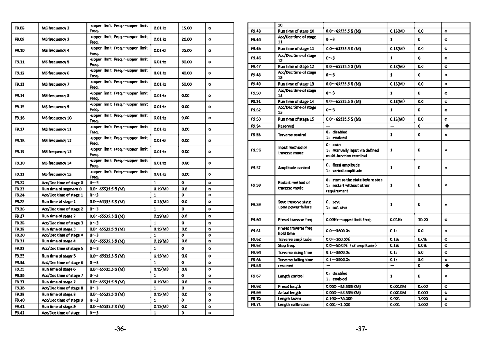
F9.08
MS
frequency 2 -upper
limit
Freq
..-...upper
limit
0.01Hz 15.00 0
Freq.
10
F9.43
Run
time
of
stage 10
0.0-65535.5
s(M) 0.15(Ml 0.0 0
F9.09
MS
frequency 3 -upper
limit
Freq
..-...upper
llmlt
0.01Hz 20.00
Freq. 0 F9.44 Ac.c/Dec
ti
me
of
stage
0-3
1 0
11
0
F9.10
MS
frequency 4 -upper
limit
Freq
..-...upper
limit
0.01Hz 25.00
Freq. 0
F9.11
MS
frequency 5 -upper
limit
Freq
..-...upper
llmlt
0.01Hz 30.00
Freq. 0
F9.12
MS
frequency 6 -upper
limit
Freq
..-...upper
limit
0.01Hz 40.00
Freq. 0
F9.45
Run
time
of
stage
11
0.0-65535.5
s(M) 0.15(Ml 0.0 0
F9.46 Ac.c/Dec
ti
me
of
stage
0-3
1 0
12 0
F9.47
Run
time
of
stage
12
0.0.-...65535.5 S n
..
.t
O.lS(M) 0.0 0
F9.48
Ac.c/Dec
time
of
stage
0-3
1 0
13
0
F9.13
MS
frequency 7 -upper
limit
Freq
..-...upper
limit
0.01Hz 50.00
Freq. 0
F9.14
MS
frequency 8 -upper
limit
Freq
..-...upper
limit
0.01Hz 0.00
Freq. 0
F9.15
MS
frequency 9 -upper
limit
Freq
..-...upper
limit
0.01Hz 0.00
Freq. 0
F9.16
MS
frequency
10
-upper
limit
Freq
..-...upper
limit
0.01Hz 0.00
Freq. 0
F9.49
Run
time
of
stage
13
0.0-65535.5
s(M) 0.15(Ml 0.0 0
F9.50
Ac.c/Dec
ti
me
of
stage
0-3
1 0
14 0
F9.51
Run
time
of
stage
14
0.0-65535.5
s(M) 0.15(Ml 0.0 0
F9.52
Ac.c/Dec
time
of
stage
0-3
1 0
15
0
F9.53
Run
time
of
stage
15
0.0-65535.5
s(M) 0.15(Ml 0.0 0
F9.17
MS
frequency
11
-upper
limit
Freq
..-...upper
limit
0.01Hz 0.00
Freq. 0
F9.18
MS
frequency
12
-upper
limit
Freq
..-...upper
limit
0.01Hz 0.00
Freq. 0
F9.19
MS
frequency
13
-upper
limit
Freq
..-...upper
limit
0.01Hz 0.00
Freq. 0
F9.54 Reserved - - 0 •
F9.55 Traverse control
o,
disabled
1,
enabled 1 0 x
Input
method
of
o,
auto
F9.56 traverse mode
1,
manuallyinputvia defined 1 0 x
multi-functionterminal
F9.20
MS
frequency
14
-upper
limit
Freq
..-...upper
limit
0.01Hz 0.00
Freq. 0
F9.21
MS
frequency
lS
-upper
limit
Freq
..-...upper
limit
0.01Hz 0.00
Freq. 0
F9.22
Ace/Dec
time
of
stage 0
0-3
1 0 0
F9.23
Run
time
of
segment O 0.0-65535.5 s(M) 0.15(M) 0.0 0
F9.24
Ace/Dec
time
of
stage 1
0-3
1 0 0
F9.57 Amplitude control
o,
fixed
amplitude
1,
varied amplitude 1 0 x
Restart method
of
o,
start
to
the
state before stop
F9.58 traverse mode
1,
restart
without
other
1 0 x
requirement
F9.25
Run
time
of
stage 1 0.0-65535.5 s(M) 0.15(M) 0.0 0
F9.26
Ace/Dec
time
of
stage 2
0-3
1 0 0
F9.59
Save
traverse state
o,
save
upon
power
failure
1,
not
save 1 0 x
F9.27
Run
time
of
stage 2 0.0-65535.5 s(M) 0.15(M)
o.o
0
F9.28 Ace/Dec
time
of
stage 3
0-3
1 0 0
F9.60
Preset traverse freq.
O.OOHz
.......
upper
limit
Freq. 0.01Hz 10.00 0
F9.29
Run
time
of
stage 3 0.0 65535.5 s(M) 0.15(M) 0.0 0
F9.30 Ace/Dec
time
of
stage 4
0-3
1 0 0 F9.61 Preset traverse freq. o.o.-...3600.0s O.ls 0.0
hold
time
x
F9.31
Run
time
of
stage 4 0.0-65535.5 s(M) 0.15(Ml 0.0 0
F9.32
Ace/Dec
time
of
stage 5
0-3
1 0 0
F9.62
Traverse amplitude 0.0.-...100.0%
0.1% 0.0%
0
F9.63
Step freq. 0.0 50.0%
(ofamplltude)
0.1% 0.0%
0
F9.33
Run
time
ofstage 5 0.0-65535.5 s(M) 0.15(M)
o.o
0
F9.34
Ace/Dec
time
of
stage 6
0-3
1 0 0
F9.35
Run
time
of
stage 6 0.0-65535.5 s(M) 0.15(Ml 0.0 0
F9.36
Ace/Dec
time
of
stage 7
0-3
1 0 0
F9.37
Run
time
of
stage 7 0.0-65535.5 s(M) 0.15(M) 0.0 0
F9.64 Traverse rising
time
0.1.-...3600.0s O.ls 5.0 0
F9.65 Traverse falling
time
0.1.-...3600.0s O.ls 5.0 0
F9.66 reserved - - 0 •
F9.67 Length control
0:
disabled
1:
enabled 1 0 x
F9.38
Ace/Dec
time
of
stage 8 0 3 1 0 0
F9.68
Preset length 0.000
65.S35(KM)
0.001KM
0.000 0
F9.39
Run
time
of
stage 8 0.0-65535.5 s(M) 0.15(M) 0.0 0 F9.69 Actual length 0.000
65.S35(KM)
0.001KM 0.000 0
F9.40 Ace/Dec
time
of
stage 9
0-3
1 0 0 F9.70 Length factor
0.100-30.000
0.001 1.000 0
F9.41
Run
time
of
stage 9 0.0-65535.5 s(M) 0.15(M) 0.0 0 F9.71 Length calibration
0.001-1.000
0.001 1.000 0
F9.42
Ace/Dec
time
of
stage 0 3 1 0 0
-36- -37-
This manual suits for next models
2


