Vitrek Xitron 2000 Series User manual

USER GUIDE
2000 Family
DC / Temperature Source
Instruments


Warranty 3
Warranty
This Vitrek instrument is warranted against defects in material and workmanship for
a period of two years after the date of purchase. Vitrek agrees to repair or replace any
assembly or component (except batteries) found to be defective, under normal use,
during the warranty period. Vitrek's obligation under this warranty is limited solely
torepairing any suchinstrument, which in Vitrek's sole opinion proves to be
defective within the scope of the warranty, when returned to the factory or to an
authorized service center. Transportation to the factory or service center is to be
prepaid by the purchaser. Shipment should not be made without prior authorization
by Vitrek.
This warranty does not apply to any products repaired or altered by persons not au-
thorized by Vitrek or not inaccordance with instructions provided by Vitrek. If the
instrument is defective as a result of misuse, improper repair, or abnormal conditions
or operations, repairs will be billed at cost.
Vitrek assumes no responsibility for its product being used in a ha-zardous or
dangerous manner, either alone or in conjunction with other equipment. Special
disclaimers apply tothis instrument. Vitrek assumes no liabili-ty for secondary
charges or consequential damages, and, in any event, Vitrek's liabilityfor breach of
warranty under any contract or otherwise, shall not exceed the original purchase
price of the specific instrument shipped and against which a claim ismade.
Any recommendations made by Vitrek or its representatives, for use of its products
are based upon tests believed to be reliable, but Vitrek makes no warranties of the
results to be obtained. This warranty is in lieu of all other warranties, expressed or
implied and no representative or person is authorized to represent or assume for
Vitrek any liability in connection with the sale of our products other than set forth
herein.
Instrument Serial Number:______________________________________________

2000I & 2000M Instrument’s User Guide, Revision B
4
Document Part Number MO-2000-M Revision C
Copyright
Copyright© 2019 Vitrek. All rights reserved.
All rights reserved. No part of this publication may be reproduced, transmitted,
transcribed, stored in a retrieval system, or translated into any language in any
form with prior written consent from Vitrek. This product’s user guide is
copyrighted and contains proprietary information, which is subject to change
without notice. The product displays and instructional text may be used or copied
only in accordance with the terms of the license agreement.
is a trademark of Vitrek. All other trademarks or
registered trademarks are acknowledged as the exclusive property of their
respective owners.
In the interest of continued product development, Vitrek reserves the right to
make changes in this guide and the product it describes at any time, without
notice or obligation.
Vitrek
12169 Kirkham Road
Poway, CA 92064
Telephone: 858–689-2755
Email: [email protected]

Contents 5
Contents
Warranty _______________________________________________ 3
Introduction_____________________________________________ 9
Product Description _________________________________________ 9
Features _________________________________________________ 10
Front Panel Controls and Connections _______________________ 11
Display __________________________________________________ 11
“POWER” Switch _________________________________________ 11
Battery Indicators__________________________________________ 12
Red “BATT CHG” Light _________________________________ 12
Green “OK” Light _______________________________________ 12
“OUTPUT” Terminals ______________________________________ 12
Keypad __________________________________________________ 13
Numeric Keys __________________________________________ 13
+/– Key _______________________________________________ 13
Arrow Keys ____________________________________________ 13
Multiplier Keys _________________________________________ 13
Units/Enter Keys ________________________________________ 14
“CLR” Key ____________________________________________ 14
“MNU” Key ___________________________________________ 14
Rear Panel Connections and Controls________________________ 15
Charging Connector ________________________________________ 15
Compensated Thermocouple Connection _______________________ 15
Interface Connectors _______________________________________ 16
2000-IE-BAT Connector__________________________________ 16
2000-RS-BAT Connector _________________________________ 16
Rear Panel Switch _________________________________________ 16
Charging the Battery _____________________________________ 19
The Internal Battery ________________________________________ 19

2000I & 2000M Instrument’s User Guide, Revision B
6
To Charge the Battery ____________________________________ 19
Charging Status _________________________________________ 20
Charging from the Charging Module___________________________ 20
Charging Modules _______________________________________ 21
Charging from an External DC Voltage Supply __________________ 22
Continuous Power from External Supply _______________________ 22
Operating the 2000 Instrument _____________________________ 23
Front Panel Operation ______________________________________ 23
Initial Power Application _________________________________ 23
Connecting to the OUTPUT Terminals ______________________ 24
Displaying Instrument Status ______________________________ 24
Numeric Data Entry _____________________________________ 26
Direct Entry of Required Output Level_______________________ 27
Changing Displayed Multiplier_____________________________ 28
Direct Entry of Temperature Data___________________________ 29
Reversing Polarity of the Present Output Level ________________ 29
Adjusting Output Level or Simulated Temperature _____________ 30
Increasing or Decreasing Output Level_______________________ 31
Changing Adjustment Value _______________________________ 32
Terminating Adjust mode _________________________________ 32
Selecting Default Power on Condition _______________________ 32
Range Locking _________________________________________ 33
Calculating Output Mode of Operation_______________________ 34
Selecting Measurement Mode______________________________ 37
Deselecting Measurement Mode____________________________ 37
Rear Panel Operation _______________________________________ 38
Using Thermocouple Simulation ___________________________ 38
Deselecting Thermocouple Simulation Mode__________________ 41
Using the Memory Options________________________________ 43
Memory Organization ______________________________________ 43
Front Panel Memory _____________________________________ 43
Rear Panel Memory______________________________________ 45
General Memory Considerations ___________________________ 46
Applications ___________________________________________ 48
Low-level DC Power _______________________________________ 48
Ensuring Stable Voltage Connections________________________ 49

Contents
7
Ensuring Stable Current Connections ________________________ 50
Process Control Industry Applications__________________________ 52
Calibrating in Process Control Environments__________________ 52
Simulating Thermocouple Systems__________________________ 55
Measuring Thermocouple Outputs __________________________ 56
Engineering Laboratory Environment Applications _____________ 57
Calibration and Maintenance ______________________________ 61
Internal Calibration ________________________________________ 61
External Calibration ________________________________________ 62
Equipment Required to Recalibrate _________________________ 62
Initiating External Calibration______________________________ 64
Performing External Calibration ____________________________ 65
Periodic Maintenance_______________________________________ 71
Internal Maintenance _______________________________________ 72
Replacing the Internal Battery ________________________________ 73
Interface Operation ______________________________________ 75
RS232 Interface Option _____________________________________ 75
Selecting RS232 ________________________________________ 76
RS232 Handshake Lines __________________________________ 76
IEEE488 Interface Option ___________________________________ 76
Remote/Local Operation __________________________________ 77
Address Selection _______________________________________ 77
IEEE488 Handshake Lines ________________________________ 77
Bus Commands _________________________________________ 78
Other IEEE488 Specific Items _____________________________ 78
Reading Data Via an Interface ________________________________ 79
Sending Data Via an Interface ________________________________ 79
Command Set for the 2000 Instrument _________________________ 79
Keypress, Simulation Command Characters___________________ 79
Firmware Version F.02 ___________________________________ 81
Extended Command Set __________________________________ 81
Command String Usage _____________________________________ 82
Setting an Output Voltage or Current ________________________ 82
Adjusting Output Level___________________________________ 83
Reading Present Output Level______________________________ 83
Internal Calibration ________________________________________ 83
External Calibration ________________________________________ 84

2000I & 2000M Instrument’s User Guide, Revision B
8
Appendix A– Output Specifications _________________________ 85
DC Voltage Output Specifications_____________________________ 85
DC Current Output Specifications _____________________________ 86
Voltage Measurement Specifications___________________________ 87
Thermocouple Specifications_________________________________ 87
Appendix B– General Specifications ________________________ 93
Warm-Up Time _________________________________________ 94
Environmental __________________________________________ 94
Isolation_______________________________________________ 94
Computation ___________________________________________ 94
Tables
Table 1: Resistance Values for Transfer 58
Table 2: Voltage Accuracy Margins 62
Table 3: Current Accuracy Margins 63
Table 4: Command Characters 80
Table 5: Shortcut Command Character Sequences 80
Table 6: Extended Command Set 81
Table 7: DC Voltage Output 85
Table 8: DC Current Output 86
Table 9: Thermocouple Simulation and Measurement Specifications 88
Table 10: CJC Stability-Simulation and Measurement 89 & 90

Introduction 9
Introduction
This chapter describes the 2000I, 2000M, 2000IN and 2000MN DC power source
instruments and highlights their features and functionalities. The 2000 instru-
ments were introduced in 1989 to support the fields of Process Control, Calibra-
tion, and General Equipment Testing.
Product Description
The 2000I, 2000M, 2000IN and 2000MN products are portable, lightweight DC
power source instruments. Their capabilities include the generation of precision
bipolar DC voltages1; precision bipolar DC currents2; the high accuracy simula-
tion of a variety of thermocouple types with optional active cold junction com-
pensation; and measurement of voltage and thermocouple outputs. On a 2000
instrument, you may enter a scaling factor, an offset factor and a “units” text
string, which enables the calibration of four 20mA loops in the “actual” units and
scaling of the transducer. Optional IEEE488 or RS232 isolated interfaces further
enhance the 2000 instruments, allowing them to be used in varying applications.
The 2000I, 2000M, 2000IN and 2000MN 2000MN instruments use microproces-
sor and digital-analog conversion technologies to produce highly flexible, accu-
rate instruments with high reliability. The combination of HCMOS
microprocessor technologies with low-power precision analog circuitry yields a
long battery life while maintaining a lightweight rugged package and a 0.5ppm
analog output resolution.
Automatic internal calibration and simple front panel (covers on) external calibra-
tion maintain high accuracy. A comprehensive range of computational abilities
enable a variety of applications.
1DC voltage expands up to 22V and down to 10nV resolution
2DC current expands up to 22mA and down to 10pA resolution

2000I & 2000M Instrument’s User Guide, Revision B
10
Note: To ensure full use of this instrument, review this complete user guide at
setup.
Features
Fully bi-polar DC voltage and current output capability.
DC output of 22 volts at 10ppm accuracy and 22mA at 40ppm accuracy.
Temperature simulation with 0.01 degree resolution, 0.03 – 0.06 degree
accuracy.
Temperature measurement with 0.1 – 0.2 degree accuracy.
Auto cold-junction compensation.
Battery or line operation.
Suited for “in field” calibration requirements of the process control indus-
try.
Portable for use in remote sites.
Functions as a “transducer replacement” with computed output levels and
enabled data entry in: psi, KPa, mmHg, and g/sec units.
Able to calibrate at the “sending” unit.
2000M and 2000MN instruments perform thermocouple simulations.
Connects in parallel with a transducer 4 -20mA output enabling to modify
its output interfaces.
Small size and weight
Low noise performance
IEEE488: Full Talk/Listen capabilities. Isolated from output circuitry up to
500V peak
RS232: Full Talk/Listen capabilities. Selectable baud of 1200 or 19,200
baud. Isolated from output circuitry up to 500V peak.
Front Panel Controls and Connections 11
Front Panel Controls and Connections
This chapter discusses the basic use of the various controls, connectors and indi-
cators on the front panel of the 2000I, 2000M, 2000IN and 2000MN DC power
source instruments.
Before using your instrument refer to the text on Charging
the Battery.
For a
complete discussion on the methods used to perform specif-
ic tasks refer to Front Panel Operation.
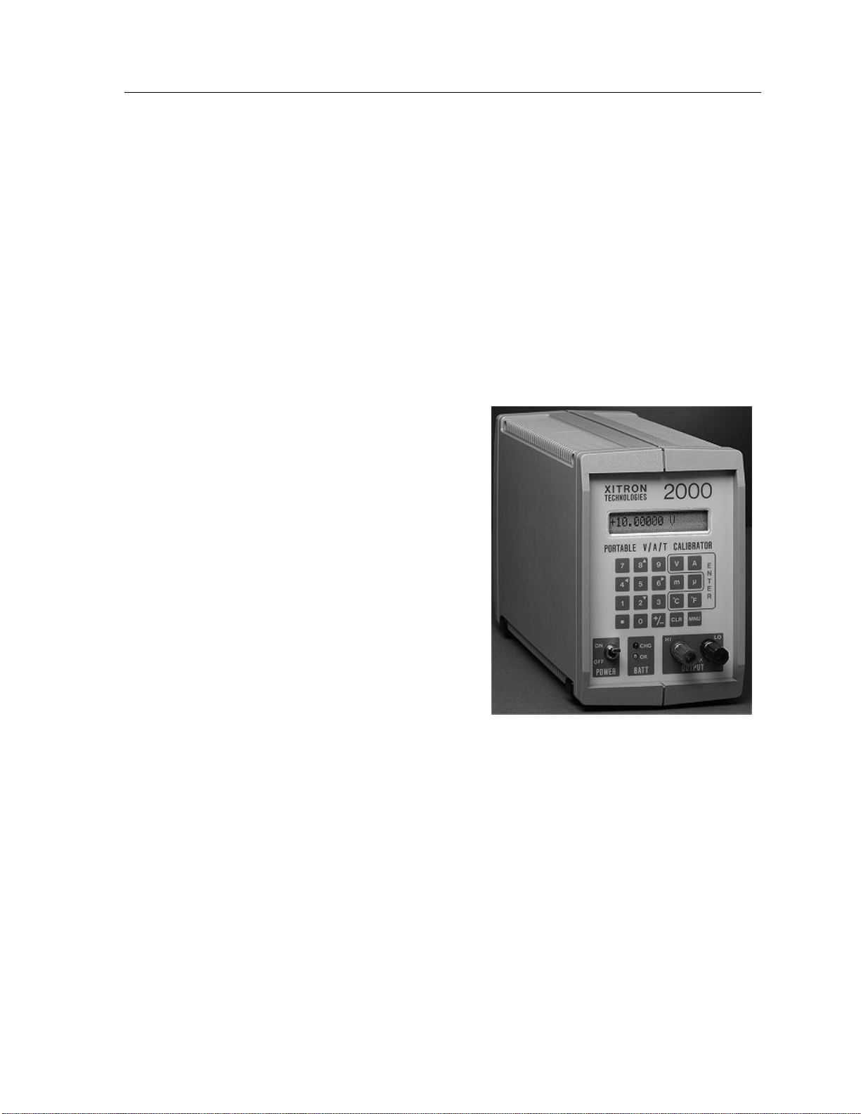
Display
The 2000 Families DC power source
instrument display is a 16 character,
single line reflective liquid crystal
(LCD). This display shows selectable
status or the present output of the
instrument.
During interactive sequences the dis-
play enables you to select a mode and
enter a value for your desired output,
calculation or measurement
.
The 2000 Instrument
“POWER” Switch
This toggle switch controls the power applied to the circuitry in the instrument.
Note that the charging module is always connected to the charging control circui-
try in the instrument, thus the POWER switch does not control the charging of the
battery.

2000I & 2000M Instrument’s User Guide, Revision B
12
When the POWER switch is toggled up, in the ON position, the microprocessor
and analog circuitry is powered and the instrument may be operated normally.
The power source may be either from the battery or the charging module, as ap-
plicable. When the power switch is toggled down, in the OFF position, the only
operation enabled is charging the internal battery.
Battery Indicators
These indicators reflect the status of the lead-acid battery (2000I, 2000M) and the
Nickel Metal Hydride batteries used (2000IN and 2000MN).
Red “BATT CHG” Light
This red light (LED) illuminates when the internal battery is being charged. Upon
full charge this light extinguishes.
Green “OK” Light
This green light (LED) illuminates when the power switch is turned on for 2000I
and 2000M. For the 2000IN and 2000MN products, the Green LED is used as a
Fuel Status indicator as well as showing that the unit is powered on. It is recom-
mended that the unit is plugged in to the supplied power supply when the Green
LED begins to flash
Note: To continue using if the light extinguishes, connect the instrument to a
charging module or an external DC supply, turn the unit off and then back on to
reset the internal cutoff circuitry.
“OUTPUT” Terminals
All output voltages, currents and temperatures are available from this pair of
binding posts mounted on the instrument’s front panel. These terminals, one red,
one black, accept banana plugs, spade leads or wires, as required.

Front Panel Controls and Connections 13
Keypad
These 20 keys are used for all manual entries into the instrument and to initiate
any required actions. These keys are in the following groups:
Numeric Keys
These keys: “0, 1, 2, 3, 4, 5, 6, 7, 8, 9,” and “.”are used to enter numeric data
into the instrument. While the display is showing the actual output level, these
keys initiate a numeric entry of a new output level; this entry will be completed
by pressing the required unit’s key.
+/– Key
The change sign (+/–) key may be used during a numeric entry to change the
polarity of the entered data. If this key is pressed while the actual output level is
being displayed (i.e., when not in a numeric entry) then the output level is re-
versed (i.e., the output polarity is changed).
Arrow Keys
During a menu selection, and during the “Adjust” mode, the “2, 4, 6 and 8” keys
are arrow keys, which scroll through various actions that show in the display.
These keys are used to select the
previous displayed action.
4 key has a (left arrow)
2 key has a (down arrow)
These keys are used to select the
next action.
6 key has a(right arrow)
8 key has an (up arrow)
To abort the selection of an activity and return the instrument to its previous con-
dition, press the MNU key.
Multiplier Keys
The “m” (milli) key and µ (micro) key are used during a numeric entry to select
the required multiplier for the entered data. If the m key is pressed then the en-
tered numeric is divided by one thousand. If the µ key is pressed then the entered
data is divided by one million.

2000I & 2000M Instrument’s User Guide, Revision B
14
Note that prior to selecting the required units key, an entered multiplier may be
changed by pressing the other multiplier or cleared by pressing the multiplier key
a second time. Pressing a multiplier key while an actual output level or measured
input level is being displayed (i.e., not during numeric entry) changes the display.
If the multiplier key is different from the display, then the display format
changes to use the selected multiplier.
If the multiplier key is the same as the display, it toggles the usage of the
selected multiplier in the display format.
Units/Enter Keys
The V, A, ºC and ºF keys are encircled within a white line on the keypad. These
keys are used to output in the selected units, which terminates a numeric entry.
They can also select the displayed action. For example in “Measure” mode
(2000M only) the V, A, ºC and ºF keys are used to change the displayed units of
the measured data.
“CLR” Key
This key is used to reinitiate a numeric entry (i.e., clear the display ready for res-
tarting the entry), or during a choice selection, this key aborts the action in
progress. During the “Adjust” mode of operation, this key deselects that mode
with the output remaining at the present level.
“MNU” Key
This key is used to select one of the “special” activities of the instrument. When
initially pressed, you are prompted to select the desired action. Press any of the
keys that have an arrow (2, 4, 6 or 8) to scroll through the textual options to dis-
play the required selection and then press a unit’s key to execute it.

Rear Panel Connections and Controls 15
Rear Panel Connections and Controls
This chapter discusses the basic use of the various controls and connectors lo-
cated on the rear panel of the 2000I, 2000M, 2000IN and 2000MN power source
instruments. For a complete discussion of the methods used to perform specific
tasks refer to Front Panel Operation.
Charging Connector
This connector, located on the rear panel in the lower right-hand corner, is the
receptacle for the connector of the charging module. See Charging the Battery
for further details regarding the usage of this connector.
Important Note: When connecting a charger other than that provided by
Vitrek, ensure the selected charger’s output voltage is: 12V at 1.5A and the
center conductor is positive polarity and uses 2.5mm DC plug.
Compensated Thermocouple Connection
This thermocouple output and measurement connections are only present on the
2000M and 2000MN instruments. Use this connection whenever the active cold
junction compensation (CJC) mode of thermocouple simulation or measurement
is being used.
This thermocouple connection, located in the lower center back of the instrument,
is wired in parallel with the output terminals on the front panel. Thus normal out-
put voltages or currents can be obtained using an uncompensated connection.
During calibration of thermocouple measuring instruments, be sure to use ther-
mocouple wire between the 2000M or 2000MN instrument and the unit being
calibrated.

2000I & 2000M Instrument’s User Guide, Revision B
16
Interface Connectors
A connector slot is available at the top center in the back panel. A connector in
this location is only present when either of the interface options IE-BAT or RS-
BAT is fitted in the instrument.
IE-BAT Connector
This is a standard IEEE488 connector, and is fitted if option IE-BAT is fitted in
the instrument. The usage of this connector and the method of using the IEEE488
interface are fully described in the Interface Operations chapter.
RS-BAT Connector
This is a female 9-pin sub-miniature D type connector, and contains the RS232
connections for the RS-BAT option of the instrument. The connections are as
follows:
1. Data Carrier Detect (Output from instrument)
2. Transmit Data (Output from instrument)
3. Receive Data (Input to instrument)
4. Data Terminal Ready (Input to instrument)
5. Ground (Common return for these signals)
6. Data Set Ready (Output from instrument)
7. Request To Send (Input to instrument)
8. Clear To Send (Output from instrument)
9. Ring Indicate (Output from instrument)
Note: These connections enable using a straight through connected cable to an
IBM AT® compatible RS232 connector. Use of this connector and the RS232
interface is fully described in the Interface Operations chapter.
Rear Panel Switch
The rear-panel mounted toggle switch is only present when the IE-BAT option is
fitted in the instrument. When ON (up position), the internal interface is enabled
for operation and is disabled when OFF (down position).

Rear Panel Connections and Controls 17
Note that the battery life is considerably shortened when the IE-BAT Interface is
enabled, thus it is highly recommended that this switch be maintained in the OFF
(down) position whenever this interface is not being used. The IE-BAT Interface
is only usable when this switch is in the ON position.

2000I & 2000M Instrument’s User Guide, Revision B
18

Charging the Battery 19
Charging the Battery
This chapter discusses the methods available for charging the internal battery and
for continuously powering the 2000 instruments from an AC power supply.
Note: Charge the battery with the IE-BAT interface option enabled, although the
time taken to recharge will be extended when the instrument is in this condition.
The Internal Battery
The 2000 instruments are powered from an internal sealed lead-acid battery
(2000I and 2000M) or a Nickel Metal Hydride battery for the 2000IN and
2000MN product builds. The battery isfullycharged when shipped from Vitrek.
During shipping or storage the battery may discharge. We recom-mend the
battery be recharged for at least 12 hours prior to its initial use. Use the charging
unit provided Vitrek to charge the internal battery and to operate this instrument.
Ensure that the included charging unit is compatible with your local power
ratings and socket connection.
Caution: If using an external DC supply other than the provided charger ensure
the selected charger’s output voltage is: 12V at 1.5A and the center conductor is
positive polarity, the DC connector is a 2.5mm Power Jack.
To Charge the Battery
A full charge to the internal battery is achieved by inserting the small plug of the
charging unit into the socket in a recess of the rear panel and then plugging the
charging unit into a suitable AC power outlet.

2000I & 2000M Instrument’s User Guide, Revision B
20
Charging Status
For battery charge status, refer to the front panel’s red BATT CHG light.
If the BATT CHG light extinguishes then the battery is fully charged.
If the BATT CHG light does not extinguish after several hours of charg-
ing, turn the unit OFF and back ON (2000I and 2000M Only).
If the light remains illuminated then continue to charge the unit for a few
more hours and retry turning the unit OFF and back ON.
And if the light still does not extinguish then replace the unit’s battery.
Charging from the Charging Module
If the internal battery has become discharged, recharge it by plugging the DC
output plug on the Charging Module’s cable end into the recessed receptacle on
the instrument’s rear panel and plugging the Charging Module into the local AC
supply. Ensure that the voltage rating of the Charging Module is in accordance
with the local AC supply voltage.
Note: For the fastest possible recharging time, place the front panel POWER
switch in the OFF position.
While charging the internal battery, the BATT CHG light will be illuminated.
When this LED becomes extinguished, the internal battery is fully charged.
The instrument can be operated while it’s charging. Note that when doing so, to
fully charge the internal battery may take up to 15 hours. If the instrument is not
operated during charging then a full charge will take up to 12 hours.
Caution: If the instrument is connected to other circuitry or instrumentation
when the Charging Module is connected, ensure that less than 500V of common
mode potential to ground is present; SEVERE DAMAGE could result if exces-
sive common mode voltages are present.
This manual suits for next models
4
Table of contents
Popular Portable Generator manuals by other brands

Agilent Technologies
Agilent Technologies ESG series Installation note

Et system
Et system EAC-4Q-KS Series manual

WURM
WURM CAN-Bridge quick start guide

Tektronix
Tektronix AFG3000 Series Quick start user manual

Parker
Parker Oildyne 108 Series instruction manual

New Holland
New Holland MN3100PR Operation manual


