Vivax Metrotech Loc-5ST Series User manual
P/N: 4.04.000073 page 1 of 10
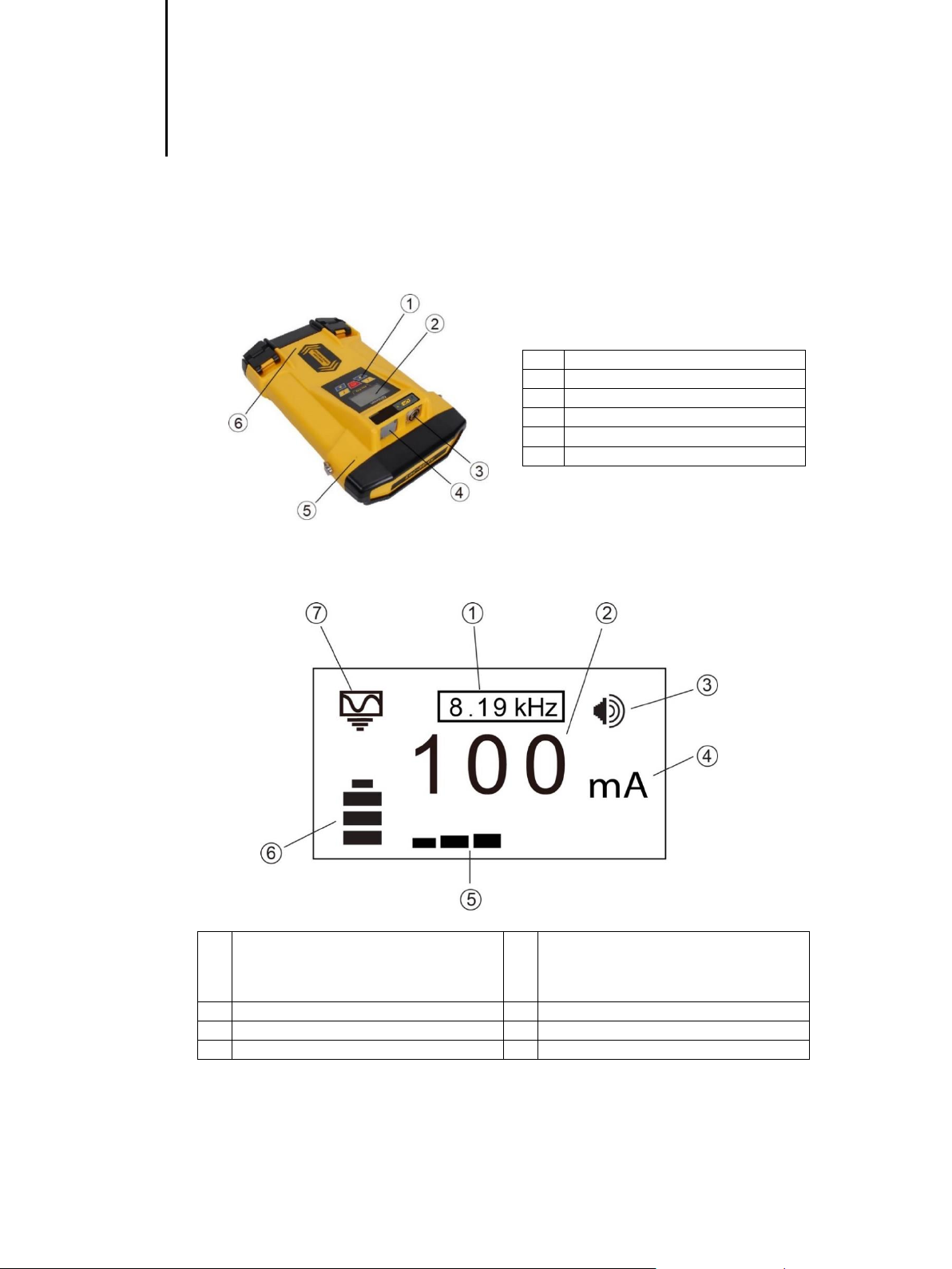
1. Loc-5STx Transmitter
1.1 Loc-5Tx Transmitter Overview
The Loc-5STx transmitter is a rugged portable transmitter powered by alkaline “D” cells or Li-Ion rechargeable
batteries. The following describes the features and uses of the transmitter.
1
Pushbutton controls
2
LCD Display
3
Single Output Connection (Loc-5STx)
4
Blanking Plate
5
Piezo beeper
6
Battery compartment
A USB socket is mounted inside the battery compartment and is used for transmitter’s firmware upgrade.
The beeper is positioned behind a small hole on one side of the housing
1.1.1 Display
1
Active Frequency
5
Output Setting (Step) (filled box indicates
current level has been reached, empty box
indicates requested current level has not
been achieved)
2
Digital Readout (mA, volts, ohms)
6
Battery Status
3
Beeper Level
7
Mode Indication Icon
4
Units (mA, volts, ohms)
External Voltage Warning
The transmitter checks the line when connected. If the line is carrying voltages in excess of 25V, it will display
the “high voltage” warning icon, and not allow the transmitter to operate. In addition, the transmitter is protected
in the event of excessive voltage or voltage spikes on the line.
P/N: 4.04.000073 page 2 of 10
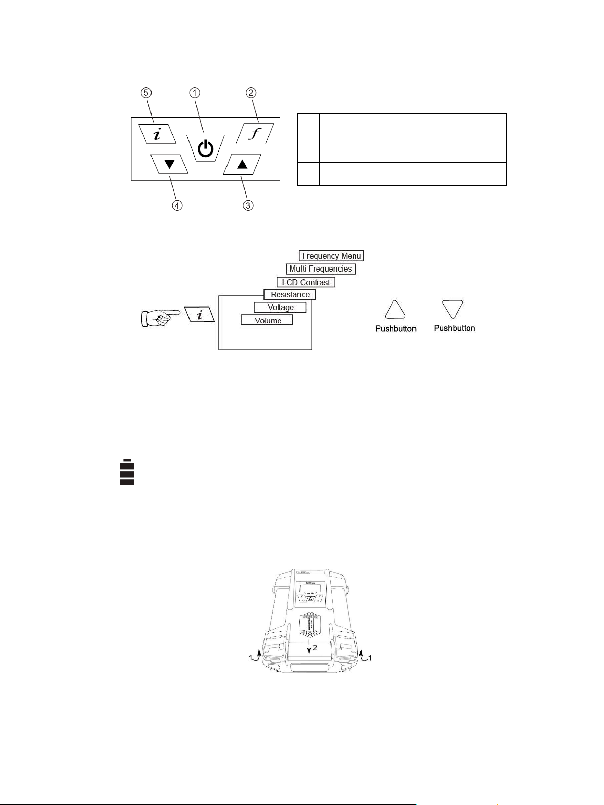
1.1.2 Pushbuttons
1
On/Off
2
Frequency Select
3
Output Increase/Navigate through menu
4
Output Decrease/Navigate through menu
5
Information (Volume, Volts, Ohms, LCD
Contrast, Multi Frequencies, Frequency Menu)
1.1.3 Information Pushbutton
When the “i” (information) pushbutton is pressed, the display will show the audio volume level , use the “+” and
“-” pushbuttons to increase/reduce the volume or turn the beeper off (off – low –medium –high).
By pressing the “i” (information) pushbutton the display can be toggled to show “voltage” and “resistance”. The
display indicates mA, as the default, and volts or ohms when selected.
1.2 Transmitter Battery
By default, transmitters are shipped with eight D cell alkaline batteries. A rechargeable Li-Ion (Lithium-Ion)
battery kit is available as an accessory. The battery status is displayed on the left side of the display.
The letters “LP” will appear when the battery status reaches only one bar. At this battery level the max output
current and power is limited.
1.2.1 Removing the Battery Tray

P/N: 4.04.000073 page 3 of 10
1.2.2 Replacing the Alkaline Battery
To access batteries –undo the two latches that are locking the battery cover
To remove batteries –remove the battery holder from the inside of the unit
Replace batteries with new batteries of the same type, be sure not to mix old and new batteries
Do not use rechargeable batteriesin the alkaline battery tray. Ensure that batteries are inserted the correct
way (see label and molded “ ” and “ ” in the bottom of the tray)
Refit the battery tray –then close the battery cover
WARNING
Alkaline Batteries –insert alkaline batteries (x 8) as shown:
1.2.3 Rechargeable Batteries
Do not attempt to replacethe rechargeable batteries or remove battery covers –return to Vivax-Metrotech
or a Vivax-Metrotech approved service centers for replacement.
WARNING
Use only Vivax-Metrotech recommended charger.
1.2.4 Re-fitting the Battery Tray
To close the battery compartment –place the two catches into their position, then close the catches.
1.2.5 Rechargeable Battery Pack Charging and Disposal
Follow the instructions in the General Safety & Care section portion of this document.
Only use the battery charger supplied with the battery. Using a non-approved charger may damage the battery
pack and could cause overheating.
The rechargeable battery pack must be connected to the transmitter in order to charge. Connect the charger
to the charging socket on the inside of the transmitter and connect the charger to a suitable mains socket.
The LED on the charger will show a red light indicating that the charge cycle is in progress.When the batteries
are fully charged the LED will change to green.
NOTE
Rechargeable pack cannot be charged from a 12V DC source.
P/N: 4.04.000073 page 4 of 10
1.3 Transmitting Modes
The transmitter has three transmitting modes, which are selected automatically.
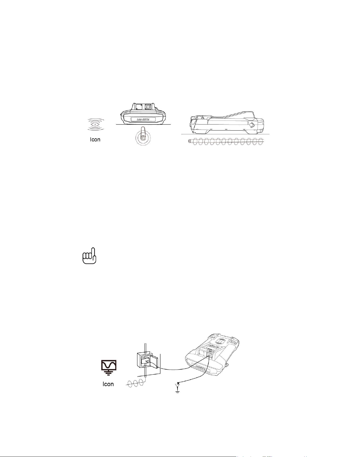
1.3.1 Induction Mode
This uses an internal antenna to induce a locating frequency onto the target pipe or cable (line). “Induction”
mode is automatically selected if no connection accessories are plugged into the “output socket”. An icon
indicating “Induction” mode shows on the display. The icon flashes when the transmitter is transmitting. In order
to generate successful induction, the transmitter should be positioned over and with the handle perpendicular
to the target line.
“Induction” mode is generally used when no access is available to make a direct connection, or a clamp
connection. When using induction it is very likely that the signal being induced onto the target line will also be
induced onto other lines in the area, and onto above ground features such as wire fences. This can influence
the accuracy of the location, depth and current measurements. “Induction” mode is also the least efficient way
of applying the transmitting signal to the target line. The distance located with “Induction” mode is generally
much less than that achieved with a direct connection or clamp connection.
“Induction” mode generally works better in higher frequencies. The advantage of induction is that no access is
required to “connect” the transmitter, making it a very quick process. The antennas on the transmitter are tuned
to induce specific frequencies or range of frequencies. Therefore only a limited number of frequencies can be
selected in “Induction” mode.
All the frequencies in favorite frequencies mode that are higher than 8 kHz can be selected by pressing “f”
pushbutton in main display. Multiple induction frequencies are available based on the user selection. See
section 1.4.2 for adding and removing frequency from the favorite frequencies list.
NOTE
For accurate location and depth measurement the locator receiver should be used
no closer than 50ft (15m) from the transmitter.
1.3.2 Direct Connection Mode
By plugging in a connection lead to the output socket, “Direct connection” mode is selected. An icon confirming
this is shown on the display. The wave in the icon fluctuate when the transmitter is transmitting. The direct
connection lead consists of two cables, one (red clip) must be connected to the conductor being located, the
other (blackclip) to asuitable ground (a ground stake is provided with the transmitter).An auxiliary ground lead
is also supplied. If the auxiliary ground lead is used, the ground clip of the connection lead (black clip) is
attached to one end of the auxiliary ground lead.
A good connection is indicated by a change in beep rate from the speaker and the current reading on the
display.
Wherever a direct connection can be safely made without the risk of injury, damage to customer’s plant, or the
transmitter, it is the best way of applying the transmitter’s signal.

P/N: 4.04.000073 page 5 of 10
The couplingof thetransmitted signal to other pipes and cables in thearea will bemuch less thanwith induction,
although where commonly bonded systems are encountered –coupling cannot be avoided.
The positioning of the ground connection can also influence the degree of coupling experienced. Ground
connections generally should not be made to other pipes or cables, or above ground metallic structures such
as wire fences. In general the lower the frequency is, the further the signal will travel, and the less signal
coupling will occur. The most common frequencies used for direct connection are between 512 Hz/640 Hz and
8 kHz.
Regulations in many countries require that power output is limited above certain frequencies. The Loc-5STx
enables frequencies below 45 kHz to be transmitted using as much as 5 watts output, but frequencies over 45
kHz are restricted to 1 watt. Using direct connection and the higher power at the low frequencies helps
significantly in achieving greater location distances. Direct connections should not be made to cables carrying
greater than 25V (or as your safety practices allow). The transmitter isprotected (250V fuse) from straycurrents
that may exist on the target line.
1.3.3 Clamp Mode
Plugging the signal clamp supplied by Vivax-Metrotech into the output socket will place the transmitter in
“Clamp” mode. An icon confirming this is displayed on the display. The icon flashes when the transmitter is
transmitting. When using the clamp no ground connection is needed.
The clamp again is a precise way to apply the locating signal. It is generally used when access to theconductor
cannot be achieved to make a direct connection (but there is sufficient access to place the clamp around the
cable), or when it is not safe to make a direct connection because the target cable is carrying electricity.
The clamp is a specialized inductive device (sometimes known as a toroid or coupler).All clamps are optimized
to work at specific frequencies. In most cases clamps are designed to beused atfrequencies generally between
8 kHz and 83 kHz. The transmitter will only allow the selection of a suitable range of frequencies for your clamp.
WARNING
When applying the clamp to cables that carry electricity –be sure to follow your
company’s safety instructions and procedures. Beware that if applied around a
high voltage cable –that cable may induce a current in the clamp causing it to
snap shut or jump quite dramatically –always apply clamps carefully.
1.4 Frequencies
1.4.1 Frequencies and Power Output
The Loc-5STx transmitter is supplied with a predefined set of transmit frequencies. The most commonly used
frequencies are preset by the factory. Additional frequencies can be added from the frequency select list. (See
section 1.4.2 for access to this menu)
Example of standard frequencies/preset at the factory are:
512Hz (where electrical systems are 60Hz) direct connection –5 watts.
640Hz (where electrical systems are 50Hz) direct connection –5 watts.
8 kHz direct connection –5 watt
33 kHz direct connection –5watt
65 kHz direct connection –1 watt.
83.1 kHz, 131 kHz direct connection –1 watt (depending on region).
200 kHz direct connection –1 watt (depending on region).
Some other frequencies with 5Watt output:
oDirection connection: 256Hz, 491Hz, 982Hz, etc.
oDirect and clamp connection : 8.19 kHz, 8.44 kHz, 9.5 kHz, 9.82 kHz, 32.8 kHz, 38 kHz

P/N: 4.04.000073 page 6 of 10
Some other frequencies with 1W output: 89 kHz, 131 kHz, 200 kHz
Clamp connection: any frequency from 8 kHz up to the highest allowed frequency (depending on region).
Induction Frequency: this transmitter is a broad-band induction unit. It means that user can select for the
Induction mode any frequency he wants, from 8 kHz up. (highest available frequency depends on region)
NOTE: see section 1.4.2 for frequency activation procedure
As with most manufacturers the clamps and induction antennas are tuned to specific frequencies, and do not
work over the complete range of frequencies.
Frequencies are selected by pressing the “f” pushbutton which toggles through the available frequencies for
the selection mode. The frequency is automatically selected if you don’t toggle past it within two seconds. The
frequency is shown on the display.
NOTE:
The output current is shown in large characters on the display –to increase or reduce the power output press
“+” or “-”. The vertical bar graph at the bottom of the display indicates which of the five current output steps is
being used. If the transmitter can supply the requested current, the bar will turn black. If the bar does not turn
black, improving the ground connections or wetting the ground where the earth stake in positioned, may help.
However, it may not be able to achieve the current setting requested because the impedance of the line is too
high for this setting. If this happens it is best to select a setting that has a black bar, this will ensure a stable
output.
The current being transmitted will be limited by the impedance of the cable, therefore it is not unusual to
increase the output level, but see no increase in the current displayed. This is not a fault with the transmitter.
The transmitter will always revert to first level output when switched on –this is a power saving feature –in
most circumstances this output level is sufficient. Increasing the output power unnecessarily will reduce the
battery life unnecessarily. All other settings remain the same as the last setting used.
1.4.2 Most Used Frequencies (Frequency Selection) Feature
This feature can be used to allow operator to choose his most used frequencies from a list of possible
frequencies. Once these frequencies are selected in the main menu, pressing the "f" pushbutton, user can
scroll through them. At any time user can add or remove frequencies from the above list, following the below
procedure. Maximum frequencies that can be appear in most used frequencies list is 12.
The advantage of this feature is that user can optimize the transmitter and activate at the main menu user’s
preferred frequencies, instead of having a whole list of frequencies that user has to scroll through.
To enter the "Frequency Menu" proceeds as follows:
1. Press the “i" pushbutton four--six times (based on the mode that transmitter is in), until get to the
"Frequency menu" sub-menu.
In Direct Connection mode,

P/N: 4.04.000073 page 7 of 10
In SD mode,
In Clamp mode,
2. Screen will show a list of frequencies available, with the central one in a box.
3. Pressing the " " or " " pushbuttons, you can scroll up or down through the available frequencies.
4. Once the wanted frequency is inside the box, press “f” pushbutton to select or deselect the frequency. An
“x” will appear in the box for a selected frequency.
5. After selecting the frequencies, press the "i" pushbutton again to exit the “Frequency Menu” and return to
the main display.
6. A particular frequency in the chosen list of frequencies can be selected from the main display screen by
pressing the “f” pushbutton until the wanted frequency is displayed at the top of the main screen.
1.4.3 Multi Frequency Mode for Direct Connection
This feature can be used when user wants to energize on target two/three frequencies at the same time. Mainly,
it can be used when user is not sure which frequency can be impressed better into the target. Multi frequency
mode is not available in Fault Find and SD modes.
NOTE
When using multi frequency mode, total power will be split between the
activated frequencies.
The frequencies have to be available in the main menu.
To enter the "Multi Freq. Setup" menu, proceeds as follows:
1. Press "i" pushbutton four times to get to the "Multi Frequency" screen and press “f” pushbutton to activate
the multi frequency mode. An “x” symbol will appear indicate the multi frequency mode is activated. Press
“f” pushbutton again to go in “Multi Freq. Setup” screen to choose the frequencies.

P/N: 4.04.000073 page 8 of 10
2. Press the " " and " " pushbuttons to scroll through the available frequencies, and bring the wanted
one in the first box.
3. Press "f" pushbutton to move the box down and the “ ” and “ ” pushbuttons to select the second
frequency.
4. Repeat step three to select the third frequency if needed.
5. Press “i” pushbutton to return to main display. On the main display, “Multi” will appear indicating the multi
frequency mode is active.
6. The frequencies selected for multi frequency mode will be saved until changes are made even when the
multi frequency mode is deactivated.
1.5 Transmitter Battery
1.5.1 Replacing Alkaline Batteries
Replace with new batteries of the same type, be sure not to mix old and new batteries.
Do not use rechargeable batteries in thealkaline battery tray. Ensure that batteries are inserted the correct
way (see label “ ” and “ ” on the side of the tray).
Refit the battery tray, place it inside the housing and close the battery cover.
WARNING
Alkaline Batteries –insert alkaline batteries (x8) as shown.
1.5.2 Rechargeable Batteries
Do not attempt to replacethe rechargeable batteries or remove battery covers –return to Vivax-Metrotech
or a Vivax-Metrotech approved service centers for replacement.
P/N: 4.04.000073 page 9 of 10
WARNING
Use only Vivax-Metrotech recommended charger.
WARNING
Charging socket
Two pins are used for power in from charger (to charge rechargeable batteries).
NOTE
Rechargeable pack cannot be charged from a 12V DC source.
Contact Vivax-Metrotech or aVivax-Metrotech approved service center for wiring diagram of plug, if attempting
to repair any of the “charging” leads.
1.5.3 Battery Charging and Disposal
Follow instructions detailed in the General Safety & Care portion of this document.
Only use the charger supplied with the equipment. Using a non-approved battery charger may damage the
batteries and cause overheating.
The charger is mains operated. Connect the charger to the battery pack at the rear of the transmitter. The LED
on the charger will show a red light indicating that the charge process has started. When the LED changes to
a green indicator the charge sequence is complete and the batteries will be fully charged.
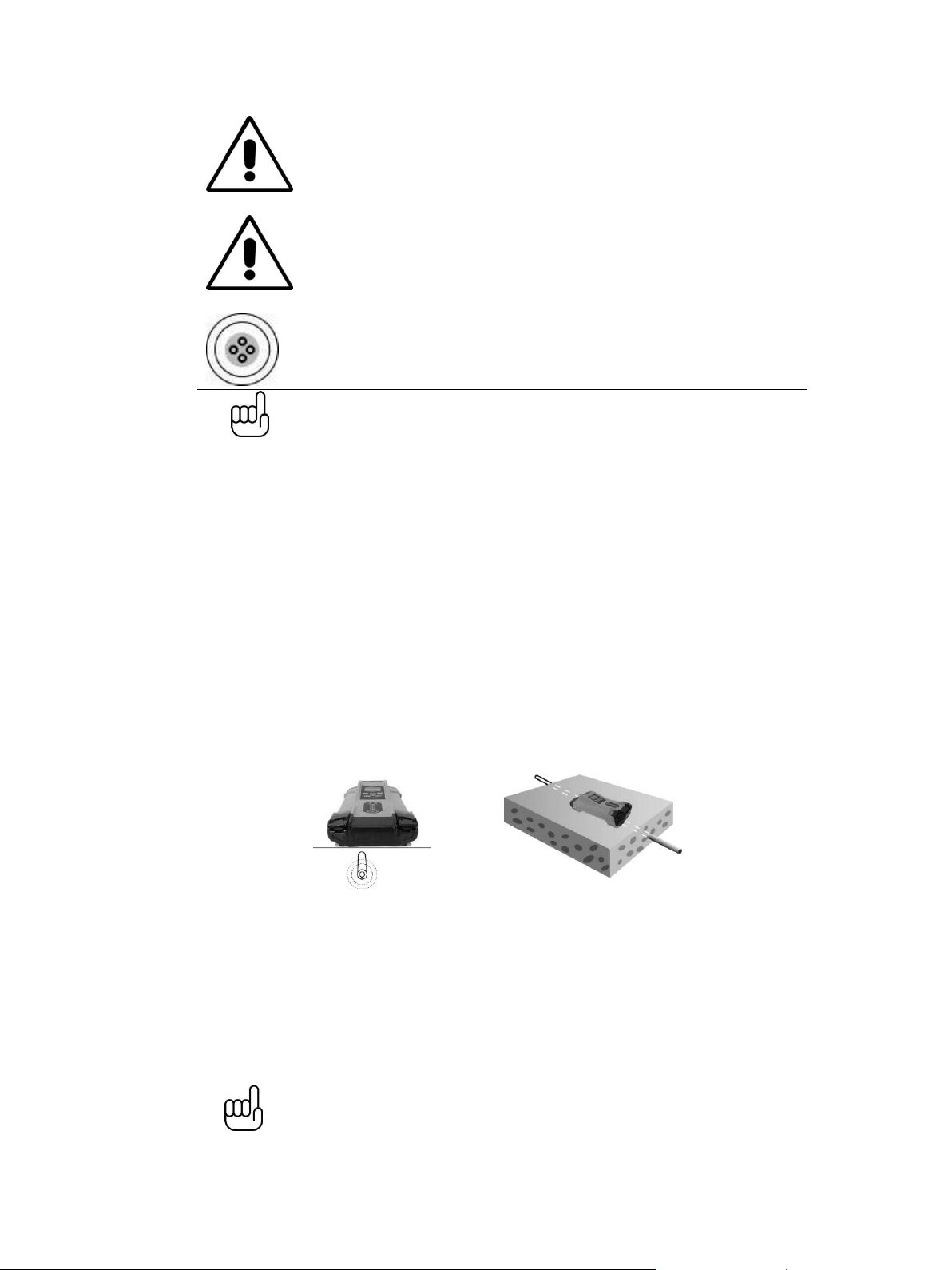
1.6 Induction Mode
Uses an internal antenna to induce a locating frequency onto the target pipe or cable (line). “Induction” mode
is automatically selected if no connection accessories are plugged into the “output socket”. In order to generate
successful induction, the transmitter should be positioned over, and in line with the target line.
“Induction” mode is generally used when no access is available to make a direct connection, or a clamp
connection. When using induction it is very likely that the signal being induced onto the target line will also be
induced onto other lines in the area, and onto above ground features such as wire fences. This can influence
the accuracy of the location, depth and current measurements. “Induction” mode is also the least efficient way
of applying the transmitting signal to the target line. The distance located with “Induction” mode is generally
much less than that achieved with a direct connection or clamp connection. “Induction” mode generally works
better in higher frequencies, usually 33 kHz up to 200kHz (depending on region). The advantage of induction
is that no access is required to “connect” the transmitter, making it a very quick process. The antennas on the
transmitter are tuned to induce specific frequencies or range of frequencies. Therefore only a limited number
of frequencies can be selected in “Induction” mode.
NOTE
For accurate location and depth measurement the locator receiver should not be
used within 50ft (15m) from the transmitter.

P/N: 4.04.000073 page 10 of 10
1.7 Direct Connection Mode
A connection lead set is supplied with the Loc-5STx transmitter. The connection lead is used to make an
electrical connection to a cable or pipe that is to be traced. One of the leads is connected to the line and the
other to a ground point that is nearby or by inserting the ground rod supplied with the equipment intothe ground
and connecting to that.
A good connection is indicated by a change in beep rate from the speaker and the current reading on the
display.
More information can be found in section 1.3.2.
1.8 Clamp Mode
The signal clamp is an optional accessory. There are three different sizes 2in (50mm), 4in (100mm), 5in
(125mm).
The clamp is generally used to apply the signal tone to a live cable or telecom cable where an electrical
connection is not possible because of safety or access issues.
Please refer to section 1.3.3 for further information.
Table of contents
Other Vivax Metrotech Transmitter manuals


