Vivax Metrotech VM-550FF Operator's manual

Locating Push Camera Cable Quick Guide
Page 1 of 7
Introduction
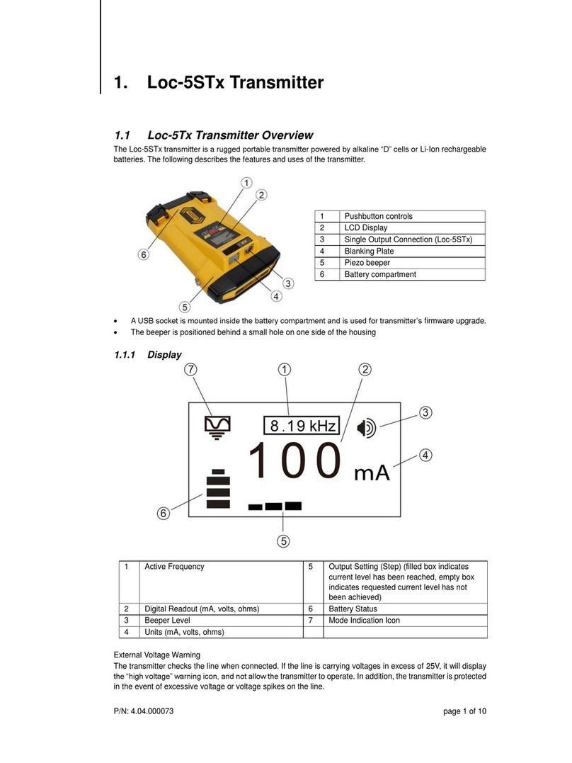
This guide describes using the VM-550FF 1-watt, and the Loc3-5Tx 5-watt transmitters to locate the pushrod cable on the Type-MX and
Type-CP cable reels. The locator being used is the vLoc3-Cam receiver, but users of the full range of Vivax-Metrotech locators will also
find it useful.
Transmitter Operational Controls
The VM-550FF Transmitter is a multi-frequency 1-watt transmitter. The FF and two low frequencies are not relevant for this application;
only the high frequency of 83kHz should be used. The locate frequency is applied by direct connection or induction. For this application,
the direct connection method must be used.
VM-550FF What's in the box
1.
VM-550FF Transmitter
2.
Ground stake
3.
Direct connection lead
4.
Transmitter carry strap
5.
4 x D Cell alkaline batteries
VM-550FF Connection Block
1.
Direct connection socket
2.
Socket cover
VM-550FF Overview
1.
On/Off button
2.
Output power select and indicator
3.
Speaker volume select
4.
Speaker
5.
Battery housing cover
6.
Connection lead socket
7.
Frequency select
8.
Frequency selected indicators
9.
Battery cover retaining screws
VM-550FF Keypad
For the purpose of locating the pushrod cable deployed in a pipe or locating a utility, only the 83kHz frequency and hi/low power options
need be used.

Locating Push Camera Cable Quick Guide
Page 2 of 7
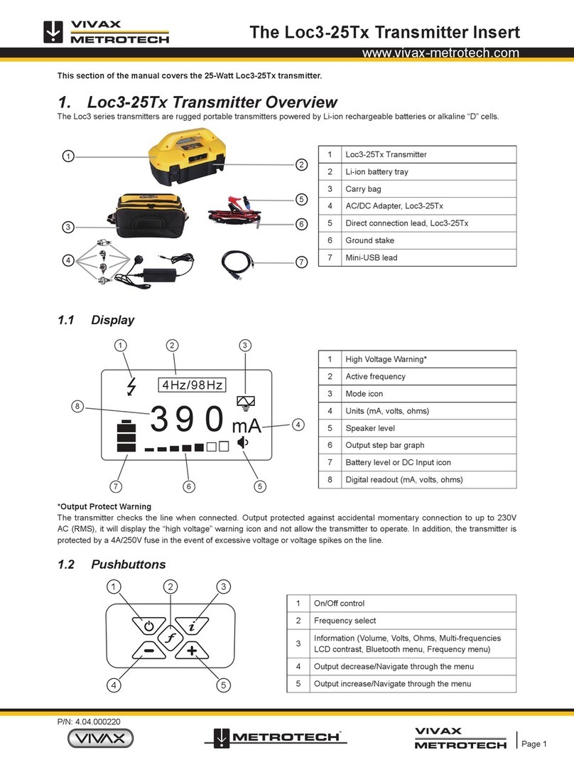
The Loc3-5Tx Transmitter is a multi-frequency 5-watt transmitter. When using this model transmitter, only frequencies above 65kHz
should be used. The locate frequency can be applied by direct connection or induction. For this application, the direct connection
method must be used.
Loc3-5Tx What's in the box
1.
Loc3 series transmitter
2.
Ground stake
3.
Direct connection lead
4.
8 x D cell alkaline batteries
5.
Alkaline battery tray
6.
Mini-USB lead
Loc3-5Tx Connections Block
1.
Connection lead socket
2.
Fuse (1.6A/250V Fuse)
3.
Loudspeaker
4.
Battery charging socket & DC input
Loc3-5Tx Keypad
1.
On/Off control
2.
Frequency select
3.
Information (Volume, LCD contrast, Frequency menu)
4.
Output decrease (Navigate through the menu)
5.
Output increase (Navigate through the menu)
Loc3-5Tx Display
1. Mode indication icon
2. High Voltage Warning (output is enabled for high voltage)
3. Frequency being transmitted
4. Loudspeaker level
5. Battery status
6. Output setting
7. Digital readout (mA, volts, ohms)
8. Units (mA, volts, ohms)
9. Tx-Link status

Locating Push Camera Cable Quick Guide
Page 3 of 7
vLoc3-Cam Receiver
1.
On/Off
4.
Increase sensitivity
2.
Reduce sensitivity
5.
Mode select
3.
Select frequency
6.
Depth readings
Active Location of the Camera Pushrod Cable
Locating the route of the deployed pushrod cable is possible with the use of a transmitter, which will apply a precise locate signal to one
of the pushrod cables conductors. The locate signal is applied by directly connecting the transmitter to the connection post of the Type-
CP or Type-MX pushrod cable reels. The picture below shows a direct connection post that the red transmitter lead connects to. The VM-
550FF is a good choice of a transmitter, providing 83kHz at 1 watt of power. However, any transmitter with a high direct connection
frequency over 65kHz is suitable for the task.
Peak Response Mode
The Line mode used to locate the pushrod cable is known as a Peak Response mode. Two horizontal antennas provide a "Peak" or
maximum signal response when over the center of the pushrod cable. The below illustration provides an example of a Peak locate signal.
The left illustration shows a low bar graph in blue and low signal strength of 18.3 when approaching the pushrod cable from right to left,
The center illustration shows the highest bar graph response and signal strength of 61.4 when directly over the pushrod cable,
The right illustration shows a low bar graph and low signal strength of 18.3 after crossing the pushrod cable and now to the left of it.

Locating Push Camera Cable Quick Guide
Page 4 of 7
Method:
•Applying a signal
1. Connect the red lead to the reels connection post.
2. Connect the black lead to a suitable ground such as a ground stake inserted in the soil. If possible, place the ground stake at
right angles to the suspected pipe direction as the earth lead may interfere with signals coming from the Pushrod cable.
Make sure the leads are not going to impede the operation of the turning pushrod cable cage.
If there is not a suitable area to insert the ground rod into the earth, it may be that the manhole access point has a metal
surround around the hole. It should be possible to make a good connection by clipping onto the surround. If the surround is rusty,
use a wire brush to clean the connection point first.
3. Select 83.1kHz frequency on the transmitter. (If 83.1kHz is not available on the transmitter, select 65kHz or 32.8kHz)
4. Insert the pushrod into the pipe and push in at least 5m (15ft) of the pushrod cable. (less than this may not provide enough signal)
•Locating the Pushrod Cable
(connect to the reel as described above)
5. Use the "Mode" button to choose the Line mode. The peak icon should be showing in the top left portion of the screen, and
the screen should look similar to the illustration below.
6. Use the "f" button to set the locators frequency to that of the transmitter.
Note that the screen will now show the addition of a compass (line direction indicator). In the presence of a locate signal, the
compass will align itself parallel to the pushrod cable being located. When the compass indicator is parallel to the pushrod cable,
the circle will be filled in blue. This ensures that the operator is aware of the direction of the pushrod cable.
7. Stand approximately 5m (6ft) from the reel and over the suspected position of the pushrod cable.

Locating Push Camera Cable Quick Guide
Page 5 of 7
8. Hold the locator vertically and rotate it on its axis until the compass indicates Forward/Back and is filled in blue color, as in the
above illustration.
9. Adjust the sensitivity control, using the "+" and "-" keys, so that the bar graph is at approximately 50%.
10. Keeping the vLoc3-Cam vertical, move to the side slightly. If the bar graph increases, you are moving toward the pushrod cable.
If it decreases, you are moving away from it.
Make the compass indicator in line and leave it blue.
11. Move toward the pushrod cable until a maximum "Peak" signal is obtained. It may be necessary to reduce or increase the
sensitivity to keep the bar graph on the scale. This is normal and should be expected. Try to keep the vLoc3-Cam vertical and
avoid swinging it as swinging may create false readings.
12. Move the locator side to side to ensure a maximum signal is detected. Use the peak level indicator to assist.
13. With the maximum signal found and the compass running Forward/Back, the vLoc3-Cam is now directly over the pushrod cable
and exactly across it.
14. The depth is also displayed in the box at the top left of the screen unless a weak signal is detected. The depth is only accurate if
the locator is directly above and in line with the pushrdo cable.

Locating Push Camera Cable Quick Guide
Page 6 of 7
15. Continue to trace the pushrod cable along the route.
As the end of the pushrod cable is reached, the signal will rapidly reduce. This is to be expected and typically will
happen a meter or two (3-6 feet) from the camera head.
At this point, the signal will start to be distorted, and the depth measurement will be affected. Check for distortion
by raising the locator a known distance such as 300mm (1ft) and check the depth changes by approximately this
amount. If it doesn't, treat the results with caution.
Distortion will also occur at the reel end of the pushrod cable.
If the exact position of the camera is required, switch the sonde on at the control box and use the vloc3-
Cam in the sonde mode to detect the camera head (see section "Sonde Location Mode.")
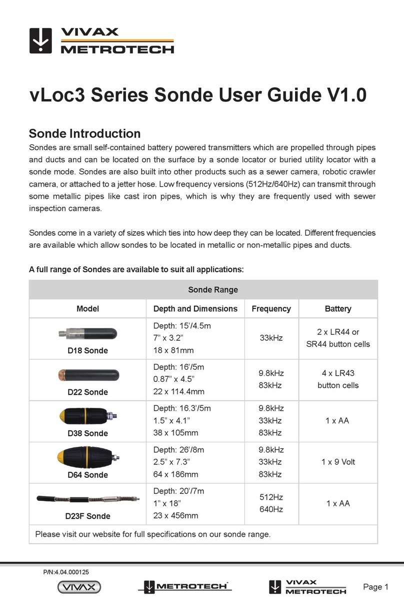
Sonde Location Mode
The sonde is located at the spring termination end, where it connects to the pushrod cable. When activated in the control module, the
sonde emits a locating signal that the vLoc3-Cam locator can detect and pinpoint.
Sonde screen icons:
1.
Peak signal detector
2.
Signal strength bar graph
3.
Sonde icon
4.
Null point
5.
Frequency selection
6.
Numeric signal level (mirrors the bar graph)
7.
Gain setting
8.
Sonde mode icon
9.
Omni Peak response icon
Method
1. Activate the sonde from the control module. Push the sonde/camera head approximately 10 to 12 feet (3-4m) into the pipe.
2. Switch on the vLoc3-Cam locator and use the Mode key to enter the sonde mode. The sonde and omni peak icons will appear in the
upper left corner of the LCD.
3. Use the "f" key to select the sonde frequency matching frequency of the control module.
Tip
Use a low frequency such as 512 or 640Hz in ferrous pipe material such as is cast iron as low frequencies penetrate metal better than
high frequencies. Also, use low frequencies when locating over re-bar as low frequencies are less likely to jump onto metal structures.
Use higher frequencies such as 32.8kHz when in PVC, plastics, or clay pipes, as this will give steadier results.
4. Hold the locator vertically and stationary with the tip on the ground.
5. If the locator is within the range of the sonde, the screen will appear similar to the one below with an arrow pointing in a particular and
steady direction. The bar graphs on either side of the screen are identical and indicate the signal strength. Use the + and – keys to
alter the receiver gain to keep the signal within the limits of the bar graph.
6. If the bar graph is not steady, it will most likely be because the sonde is not within range. In this case, hold the locator at approximately
45 degrees to the ground and rotate the locator around a full 360 degrees around you.
7. Note the direction of the strongest signal and walk towards it until the bar graph shows a steady signal. Now revert to step five above.
8. Slowly walk in the direction of the arrow.
9. A double circle will appear on the screen. This double circle indicates the position of a null signal. Walk toward it and position it over
the crosshairs of the screen. Now rotate the locator so that the arrow is pointing forward.

Locating Push Camera Cable Quick Guide
Page 7 of 7
10. Keeping the null indicator on the vertical line, walk toward the arrow.
11. A Sonde icon will soon appear (Note that the arrow is not shown when the sonde icon appears). Keeping the locator vertical, carry on
walking toward the Sonde until it is positioned on the crosshairs. The locator is now directly over the Sonde. Note that the depth of
the sonde is also displayed.
12. The diagram below provides an overview of the process:
Overview
13. Note that when directly over the Sonde, it may be necessary to confirm the position of the Sonde, left to right. Do this by moving the
locator left to right to identify the location of the strongest signal, as indicated on the bar graph. At this time, the depth to the Sonde
will be displayed at the top of the display.
14. Having pinpointed the position of the Sonde/camera head, it can now be pushed into a new location, and the process repeated. It is
advisable to keep the survey intervals too short distances such as six feet (two meters) as this makes the process of locating easier.
Vivax-Metrotech Corp. (Headquarters)
3251 Olcott Street, Santa Clara, CA 95054, USA
T/Free: 800-446-3392
Tel: +1-408-734-1400
Website: www.vivax-metrotech.com
Visit us at www.vivax-metrotech.com to view our full product line and worldwide locations.
Other Vivax Metrotech Transmitter manuals
