Vivid DVV212-A User manual

1
Installation Manual
SoftwareVersion 1.0H/2.0E
Part Number: DVV212-A
Document Number: 156
Manual by: Owen P Walker / Emilijo Mihatov
Copyright © 2000

2
IMPORTANT NOTICE
COPYRIGHT
The material in this document is copyright, and may not be quoted or reproduced in any
form without written permission from Fairlight ESP Pty Ltd.
LIMITED WARRANTY POLICY
All the software and hardware provided with, or purchased especially for, Fairlight
products has been tested for functionality. Fairlight ESP Pty Ltd will make its best efforts to
correct reported defects for future releases subject to technical practicabilities. Fairlight ESP
will also replace any defective media on which software has been delivered provided that the
item to be replaced is returned to the dealer who supported the product within 90 days of
purchase.
Fairlight ESP Pty Ltd makes no warranty or representation either expressed or implied
with respect to the system's performance or fitness for a particular purpose.
In no event will Fairlight ESP Pty Ltd be liable for direct or indirect damages arising from
any defect in the product or its documentation. Further, Fairlight ESP Pty Ltd will not accept
any liability for any programs, sounds, audio recording, video recording or sequences stored
in or used with Fairlight products, including the cost of recovery of such data.
The warranties, remedies and disclaimers above are exclusive and take precedence over
all others, oral or written, express or implied, to the extent permitted by law in the
geographical area of the product's use. No employee of Fairlight ESP, agent, distributor or
employee of an agent or distributor is authorized to offer any variation from this policy.
Copyright 2000:
Fairlight ESP Pty Ltd,
Unit 2, 1 Skyline Place,
French's Forest, NSW 2086,
AUSTRALIA.
Telephone +61 2 8977 9999
Fax +61 2 8977 9900

3
TABLE OF CONTENTS
IMPORTANT NOTICE ......................................... 2
CERTIFICATES & COMPLIANCES ........................... 4
SAFETY SYMBOLS ............................................ 5
MAINS PLUGS & MAINS POWER CORDS .............. 6
OBTAINING TECHNICAL SUPPORT ........................ 7
SECTION 1 - INTRODUCTION ............................. 8
1.1 Product Description .............................. 8
1.2 Manual Summary ................................. 8
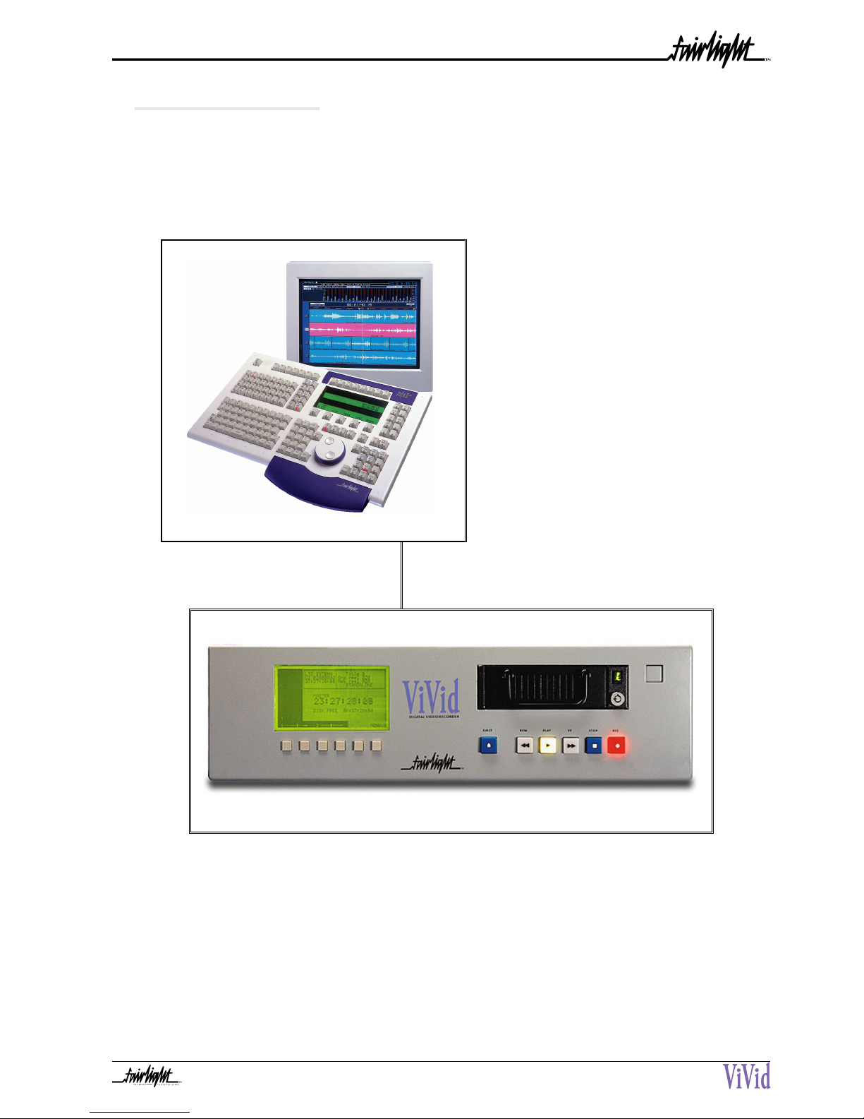
1.3 System Overview ................................. 9
1.4 Unpacking .......................................... 10
1.5 Equipment Supplied ............................ 10
1.6 Static Precautions ............................... 11
1.7 Environment........................................ 11
SECTION 2 - INSTALLATION OF VIVID ................ 12
2.1 Mechanical Installation ...................... 12
2.2 Electrical Installation .......................... 13
2.3 ViVid Rear Panel Connections ............. 13
2.4 Cabling ............................................... 14
2.5 External Cable Considerations ............ 14
2.5.1 SONY 9 PIN CABLE ....................... 14
2.5.2 VIDEO CABLES .............................. 14
2.5.3 LTC CABLE ................................. 14
2.5.4 AUDIO CABLES ............................. 14
2.6 Connecting The Various System
Components .............................................. 15
2.7 Internal and External SCSI Devices .... 16
SECTION 3 - SYSTEM CONFIGURATION ............... 17
3.1 Introduction......................................... 17
3.2 Switching on the ViVid ..................... 17
SECTION 4 - ROUTINE MAINTENANCE ................ 18
4.1 Cleaning The Exterior Of The ViVid ..... 18
APPENDIX - SPECIFICATIONS ............................. 19
Introduction ............................................... 19
Reference Signal Input ............................. 19
Analogue Video Input and Output ............. 19
Signal Inputs and Outputs ......................... 19
Dimensions ............................................... 20

4
CC EMISSION CONTROL
This equipment has been tested and found to comply with the limits for a Class A digital
device, pursuant to Part 15 of the FCC Rules. These limits are designed to provide reasonable
protection against harmful interference when the equipment is operated in a commercial
environment. This equipment generates, uses, and can radiate radio frequency energy and, if
not installed and used in accordance with the instruction manual, may cause harmful
interference to radio communications.
The ViVid conforms to the EMC directives :-
EN 55022:1998 Class A - Emissions
EN 50082.1.1995
The ViVid also conforms to the Safety directives :-
UL 1419 - Professional Video & Audio Equipment
IEC 60950 - Information Technology Equipment
For further information on EMC procedures please refer to the following titles:-
Noise Reduction Techniques In Electronic Systems by Henry W Ott
EMC by Tim Williams
Operation of this equipment in a residential area is likely to cause harmful interference in
which case the user will be required to correct the interference at his own expense. Changes
or modifications not expressly approved by Fairlight ESP can affect emission compliance and
could void the user’s authority to operate this equipment.
CERTIFICATES & COMPLIANCES
CHARACTERISTICS DESCRIPTION
Equipment Type Supplemented Data: Information Technology
Equipment Class Supplemental Data: Class 1 - Grounded equipment
Installation Catergory Requirement Category 2 - Local level appliances,
portable equipment etc.
Pollution Degree
Requirement: Level 2 operating environment -
Normally only non-conductive pollution occurs.
Occasionally there may be a temporary conductivity
caused by condensation.

5
SAFETY SYMBOLS
The lightning flash with arrowhead symbol, within an equilateral
triangle, is intended to alert the user to the presence of un-insulated
“dangerous voltage” within the product’s enclosure; that may be of
sufficient magnitude to constitute a risk of electric shock to persons.
L’eclair, dans une triangle, est destiné à alerter l’utilisateur de la
présence de haute tension dangereuse non isolée dans l'enclosure du
produit, qui peut être d’un voltage suffisant pour constituer un risque
d’électrocution.
Das dreieckige Schild mit Blitzsymbol soll den Benutzer vor
unisolierten Hochspannungen innerhalb des Gerätes warnen. Es
besteht Lebensgefahr durch elektrischen Schlag!
El simbolo del rayo dentro de un triángulo equilátero, es usado
para indicar la presencia de un voltage peligroso en el interior del
aparato, de suficiente intensidad, como para constituir riesgo de
electrocución a las personas.
The exclamation point within an equilateral triangle is intended to
alert the user to the presence of important operating and maintenance
instructions in the literature accompanying the appliance.
Le point d’exclamation dans une triangle est destiné à alerter
l’utilisateur de la présence d’instructions importantes de
fonctionnement et d’entretien dans la littérature accompagnant
l’appareil.
Das dreieckige Schild mit Ausrufungszeichen soll den Benutzer auf
wichtige Bedienungs- und Wartungshinweise in der
Bedienungsanleitung hinweisen.
El simbolo de exclamación dentro de un triángulo equilátero avisa
al usuario de la presencia de instrucciones importantes acerca del
funcionamiento y mantención del aparato en los documentos que se
incluyen.

6
MAINS PLUGS & MAINS POWER CORDS
The following lists the recommended Mains Plugs and Leads for use in various countries
throughout the world.
Standards applicable for Mains Plugs Rating Country
ASTA BS1363 1984 10A @ 250VAC UK
BS546, 1950 10A @ 250VAC India, Kenya, Nigeria, Kuwait,
Parts of Asia and the Far East
IEC695-2-1 & NF-USE 10A @ 250VAC France & Belgium
DIN49441 & CEE 7 Sheet VII 10A @ 250VAC Europe
SEV 10A @ 250VAC Switzerland
CEI23-16 10A @ 250VAC Italy
NEMA5-15P & NEMA6-15P 10A @ 250VAC USA
Standards applicable for Mains Leads Rating Country
CSA22.2 No.42 & UL498 10A @ 250VAC Canada & Japan
ASE 1011 (1959) 10A @ 250VAC Switzerland
CEI 2316 10A @ 250VAC Italy
SRAF 1962 10A @ 250VAC Denmark
AS3112-1990, NZSS198-1967 10A @ 250VAC
Australia, New Zealand, Fiji,
Papua New Guinea, Republic of
China
UL498 & SJT 10A minimum rating with IEC60320-
1 coupler 10A @ 250VAC USA
Mains Attachment Plugs
Mains Power Leads

7
OBTAINING TECHNICAL SUPPORT
Users requiring technical support should contact their local Fairlight office or distributor.
Information can also be found on the world wide web at :-
http://www.fairlightesp.com
United Kingdom USA – West Coast
Fairlight ESP Limited
Unit 12, Spectrum House
32-34 Gordon House Road
London NW5 1LP
England
Tel: +44 171 267 3323 Fax: +44 171 267 0919
Fairlight USA
844 North Seward Street
Hollywood CA90038
USA
Tel: +1 323 465 0070 Fax: +1 323 465 0080
France USA –East Coast
Fairlight France
41-43 Rue des Peupliers
92100 Boulogne-Billancourt
Paris
France
Tel: +33 1 4610 9292 Fax: +33 1 4610 9295
Fairlight USA
2 West 45th Street, Suite 605
New York NY 10036
USA
Tel: +1 212 819 1289 Fax: +1 212 819 0376
Germany Japan
Fairlight Deutschland Gmbh
August-Bebel-Strasse 26-53
14482 Potsdam-Babelsberg
Berlin
Germany
Tel: +49 331 721 2930 Fax: +49 331 721 2933
Fairlight Japan Inc
Seijyo 4-2-23, Setagaya-Ku
Tokoyo 157-0066
Japan
Tel: +81 3 5940 1515 Fax: +81 3 5940 1516
Asia –Pacific
Fairlight ESP Pty.limited
Unit 2, 1 Skyline Place
Frenchs Forest NSW 2086
Australia
Tel: +61 2 8977 9999 Fax: +61 2 8977 9900

8
SECTION 1 - INTRODUCTION
1.1 PRODUCT DESCRIPTION
ViVid is a general purpose video and audio recorder that can be used in a number of
professional applications where reliable and fast access to non-linear video and audio is
required. Its main purpose is to act as a video-follow device during editing sessions with
MFX3plus and other Fairlight Products.
The disk recorder takes PAL or NTSC composite analogue video, audio and LTC timecode
signals and digitises them in real time onto a high speed magnetic disk drive. The file can then
be played with all signals being output in sync with each other, using the front panel or Sony
9-pin remote control.
For a more detailed explanation of the ViVid, please refer to the ViVid User Manual.
1.2 MANUAL SUMMARY
The purpose of this manual is to provide all the technical information required to design a
suitable installation for the ViVid system and to fit and connect the units. It is assumed that the
installer is familiar with video and audio post production including analogue and digital video
and audio signals. For full operational instructions please refer to the ViVid User Manual.

9
1.3 SYSTEM OVERVIEW
The ViVid system is made up of one main rack mountable unit. The system is normally
connected to a video monitor and a source device, such as a video tape recorder.
The ViVid can be remote controlled from other devices such as the Fairlight MFX range of
digital audio workstations via the Sony RS422 protocol. In such a configuration an audio
mixer, such as the Fairlight Fame or Prodigy, can also be configured to control the ViVid.
ViVid
MFX3plus Digital Audio Workstation

10
1.5 EQUIPMENT SUPPLIED
1.4 UNPACKING
It is advisable that before any installation work is attempted that the system be unpacked
and the contents verified. A sizeable area approximately 3 meters square should be suitable.
Using the basic packing list attached record the items you have received. This will both help
you when you have to make an enquiry, by having the relevant details logged in your
Installation Manual, in the event of a packing omission. At this stage do not power up the
system, nor remove electronic modules from the system, as damage may occur if not handled
correctly.
EQUIPMENT SUPPLIED QUANTITY CHECK LIST
ViVid 1
IEC Mains Cable 1
ViVid Installation Manual 1
ViVid User Manual 1
BNC 75 Ohm Terminator 2

11
1.6 STATIC PRECAUTIONS
Please take note that all Fairlight manufactured electronic modules are static sensitive
and should be handled under anti-static conditions. When working on a system always
ensure that you have an anti static lead connected and that the system is connected to
ground through an earth lead.
Never work on the system while powered up unless you are authorized by Fairlight to
do so. As a matter of practice always touch the external chassis of the system before
opening the front panel. If cards are not handled under anti static procedures your
machine may sustain damage which could either cause a complete failure or may cause
intermittent crashes and subsequent system failure.
When handling cards please ensure that they are placed in anti static bags when not in
the system. For shipment purposes electronic modules should be placed in an anti static
bag and then suitably surrounded with loose packaging materials in a solid card board
box. Cards shipped to Fairlight without the correct anti static packaging will have their
warranty voided. If you have any enquiries on this matter please feel free to contact your
local Fairlight office or distributor.
1.7 ENVIRONMENT
The system is designed to be operated in a clean air-conditioned environment.
Generally, an area comfortable for people ( 20°C - 21°C ) should be suitable. The ViVid uses
fans for its forced ventilation system, these generate an amount of ambient noise. Users
may find it desirable to install these units away from the operator/console location. Note
that cable lengths, as detailed in Section 2.5 - External Cable Considerations, should be
taken into account when planning the installation.
Make sure that the rack units can access cool air through the opening on the base or top
of the front panel, and expel warm air from the fans at the rear of the system. As with all
computer systems, the Fairlight will operate more reliably if static generating floor
coverings are avoided.
Do not fit the ViVid into a closed environment except where ducted air is forced
through the rack. Do not run the ViVid whilst it is on the ground as it will accumulate dust,
which may eventually cause a failure.
The ViVid is normally installed in a suitable 19" rack which is at least 600 mm deep, or
has an open back section. It is recommended that external hard drives be mounted on a
rack tray, above or below the system, using the shortest possible cables to prevent SCSI
bus corruption.
Please Avoid:
Fitting the ViVid where air circulation will be restricted.
Installing ViVid close to heat sources.
Installing in dusty or damp area.
Installing in an area subject to vibration.
Installing in area with strong magnetic or electric fields

12
SECTION 2 - INSTALLATION OF VIVID
The ViVid unit, takes up 3 RU, when fitted into a 19" rack. It operates from either 100-120v
or 200-250v, 50-60Hz with the mains inputs being auto-switching. There are no switches to be
set.
1. If the ViVid is to be installed into a rack, the four feet on the underside of the system
need to be removed using a philips screwdriver.
2. Next remove the front dress panel, to allow access to the rack mount holders on the
ViVid.
3. Mount the ViVid into the rack and insert 4 rack retaining screws on to both the left and
right rack mounts. Once this is done reattach the front dress panel.
2.1 MECHANICAL INSTALLATION
ViVid Front Panel

13
2.2 ELECTRICAL INSTALLATION
The ViVid is designed to run from a single phase power source with one of its current
carrying conductors at or near earth ground potential (the neutral conductor). Only the line
(live) conductor is fused for over-current protection. Systems that have both current carrying
conductors live with respect to ground , such as phase-to-phase in multi-phase systems are
not recommended as power sources.
It is recommended that both the ViVid and its peripheral equipment are connected to the
same electrical supply or ring main which ideally should be regulated and smoothed. If the
power source is likely to be unexpectedly cut then both the units should be fed from a backed
up power source such as a UPS.
Mains connections should be fitted with the appropriate type of plug. See Section “Mains
Plugs & Power Cords” at the front of this manual.
2.3 VIVID REAR PANEL CONNECTIONS
The ViVid rear Panel is split into four distinct sections; Video I/O , Audio I/O , Timecode I/O
and Communications I/O.
The Video I/O Panel contains connections for 1 Composite Analogue Video Input and
Output, 1 Y/C Input and Output and 1 Video Reference In and Loop Through.
The Audio I/O Panel contains 2 Analogue Input Channels and 2 Analogue Output
Channels.
The Timecode Panel contains LTC In and Out.
The Communications Panel contains a Sony 9 Pin port to allow the ViVid to be remote
controlled from other devices, a Network Port and a SCSI Port.
ViVid Back Panel

14
2.5 EXTERNAL CABLE CONSIDERATIONS
Poor cabling can be the bane of a good system. Earth loops, floating inputs and outputs
and extended runs are just some of the issues to be addressed when planning an installation.
2.5.1 SONY 9 PIN CABLE
The 9-Pin cable connects the Mainframe to a Sony 9-pin protocol machine. The
recommended maximum length for this cable is 30 meters. It is recommended that the power
be switched off at one end when connecting to protect the drivers.
2.5.2 VIDEO CABLES
Standard 75 ohm shielded coaxial cable is suitable.
2.5.3 LTC CABLE
Standard 75 ohm shielded coaxial cable is suitable.
2.5.4 AUDIO CABLES
Standard, shielded balanced audio cable is suitable.
The interconnecting cables supplied as standard may not be long enough for your
installation, in which case you must provide longer cables. The following information gives
specific wiring details and highlights any special requirements, however as with all equipment
not supplied with the ViVid system, it is the installer’s responsibility to ensure that these
cables comply fully with the applicable safety and EMC regulations.
2.4 CABLING
Once the mechanical installation of the ViVid is complete, a number of cables must be
connected. Some of these connect various components together and may have been supplied
with the system, others provide connection to the rest of the environment.

15
2.6 CONNECTING THE VARIOUS SYSTEM COMPONENTS
1 Once cabling issues have been dealt with the various system connections
need to be made.
2 Connect an IEC Power lead to the back of the ViVid.
3 Connect the audio inputs and outputs to the XLR connectors on the rear
of the unit.
4 Connect the video source signal to VIDEO IN using either the composite
BNC Input, or the Y/C Input connector.
5 Connect a cable from the Video Out or Y/C Out Connector to an external
picture monitor.
6 To lock the ViVid to an external video reference, connect the source to the
REF IN Port.
7 To allow an external timecode to be used with the ViVid, connect a time
code source to the LTC In Port.
8 Connect a 9-Pin control cable from an external device to the ViVid via the
Sony 9- pin Port.
1. If terminator switches are fitted to your unit, they must be switched to the on position if
there are no other video devices connected to the Video Loop thru connector.
2. If there is no termination switches fitted, you must connect the terminators supplied to the
video loop through if there are no devices to be connected to these sockets.

16
2.7 INTERNAL AND EXTERNAL SCSI DEVICES
The ViVid has been designed to accept one 5.5”drive bay internally which can hold a
Kingston Technology DE-100 SW drive enclosure. The system typically comes configured
with one system disk which contains the Operating System and ViVid software. This allows
for one media drive to be fitted internally in the system.
Kingston De-100 SW Drive Enclosure

17
SECTION 3 - SYSTEM CONFIGURATION
3.1 INTRODUCTION
The following describes the procedure for powering on ViVid.
CAUTION : NEVER ATTEMPT TO AT TACH SCSI BASED DISK DRIVES OR OTHER CABLING WHILE THE
SYSTEM IS RUNNING AS THIS MAY CAUSE FILE AND PROJECT CORRUPTION. ALWAYS POWER OFF
BEFORE CONFIGURING ANY CABLES.
3.2 SWITCHING ON THE VIVID
1. Press the Power switch located on the front of the ViVid.
2. The unit will show the SCSI ID flashing while the disk drive spins up. Drive
activity is denoted by the flashing green dot in the drive indicator.
3. The LCD screen will display the message -
“Welcome to ViVid
INITIALISING...”.
After about 90 seconds this message will be replaced by the audio level meters
and time code display indicating that the unit is ready for use.
Power On Switch
LCD Screen SCSI ID

18
4.1 CLEANING THE EXTERIOR OFTHE VIVID
You should clean the ViVid unit often enough to prevent dust or dirt from accumulating.
Dirt acts as a thermal insulating blanket that prevents effective heat dissipation and may
provide high-resistance electrical leakage paths between conductors or components in a
humid environment.
Clean the dust from the outside by wiping with a soft cloth or small brush. A brush is
especially useful for removing dust from around connectors and cooling grilles. Use a cloth
dampened in water that contains 50% isopropyl alcohol to remove hardened dirt. You should
not use abrasive cleaners. Remove power from the ViVid before cleaning.
CAUTION:
Do not allow water to get inside any enclosed assembly or conponent, do not clean any
plastic material with organic cleaning solvents such as Asbenzene, Toluene, Xylene, Acentone
or similar conpounds, because they may damage the plastic.
SECTION 4 - ROUTINE MAINTENANCE

19
APPENDIX - SPECIFICATIONS
INTRODUCTION
The following information contains all the wiring details and specifications to allow users
to connect peripheral devices to the back panel of the ViVid.
REFERENCE SIGNAL INPUT
Reference Video Connector BNC
Input Level 1V p-p 75 Ohms
ANALOGUE VIDEO INPUT AND OUTPUT
Television Standard PAL-CCIR 625/50
NTSC 525/60
Signal Processing CCIR 601, 4:2:2, 8 Bit
Genlock B.B 1.0V p-p
SIGNAL INPUTS AND OUTPUTS
Video Connector BNC - Y/C
Input Level 1V p-p 75 Ohms
Audio Connector Balanced XLR
ViVid Back Panel
Timecode BNC
Input 0.5 V p-p to 18- V p-p
Output 3.0 V p-p

20
DIMENSIONS
Height 13 cm (3RU)
Depth 48 cm
Width 48 cm
Weight approx 14kg
Notes :
Table of contents
Other Vivid DVR manuals