Vivint SmartHome VS-SH2000-000 User manual

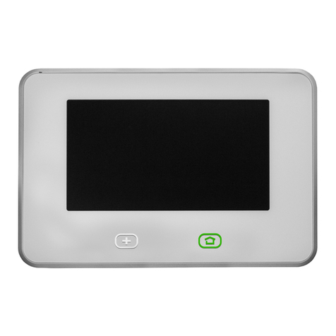
Smart Hub Panel (front view) —
Smart Hub Panel (back view with mounting plate removed) —
Operation Overview / User Functionality
Once the Smart Hub is up and running, the user can perform the following functions (among others) at the panel
and via the
web and mobile apps. For details, refer to online Help at the Vivint Support site: support.vivint.com.
The Smart Hub monitors and manages all aspects of your
integrated smart home system, including security sensors
(door/window, motion, etc.), detec
tors (smoke, CO, etc.), and automation devices (cameras, door locks, etc.). The
touchscreen display
provides critical status information, alerts, and activity history; and lets you access video, audio
,
and emergency features, arm & disarm security, customize the panel, and configure and control peripheral devices.
MAIN FEATURES — WHAT YOU CAN DO WITH THE SYSTEM
•Arm and disarm the security system (Stay & Away)
•Activate alarms with Panic, Emergency and Fire buttons
•Talk with the Vivint Central Station using two-way voice
•Acknowledge and clear alert notifications
•Add, configure and control smart home devices & users
•And more… (refer to the online Help resources)
FC
The Vivint
Smart Hub™ panel is the central component of the Vivint Smart Home™ system, a fully
supervised
, integrated, and intelligent home security and smart home automation ecosystem.
The
system — control panel and various security sensors, detectors, and smart home devices —
incorporates the most advanced
, sophisticated technologies and functionality available today. The
system can be expanded and customized to fit individual home environment
s and customer needs.
The Smart Hub features a
touchscreen display that allows control of all system functions. The display
shows
time & weather, and status of the network, power, sound, and overall system security. Touch-
screen
navigation makes device configuration and operation quick and easy. Microphone and speaker
provide
two-way voice capability, and the downcast light indicates security status. The panel runs
system
software
that can be updated with the latest release to add new features and enhancements.
This document includes a product description, illustrat
ions, basic system operation / user functionality,
as well as technical specifications
, standards listings, and patent and regulatory compliance references.
Vivint Smart Hub Panel
(VS-SH2000-000)
Quick Reference (Overview, Installation, Specs, Regulatory)
PRINT INSTRUCTIONS: REFERENCE SHEET FOR VS-SH2000-000 P/N 77-600031-001 REV 1.4 |
INK:
BLACK | MATERIAL: 20 LB MEAD BOND | SIZE: 8.50" X 11.00" SCALE 1:1 |
FOLDS:
BI-FOLD VERTICAL, BI-FOLD HORIZONTAL (TO FIT IN BOX)
Standards Certifications and Listings
FCC
47CFR Part 15, Subpart B, Class B; and 47CFR Part 15, Subpart C
ISED Canada
CAN ICES-3(B)/NMB-3(B); RSS-GEN; RSS 210/CNR 210
Safety Certification
cETLus Listed; ETLus Classified
CSFM Listing
7167-2147:0100
Z-Wave Alliance
ZC10-18106282
UL 985
Standard for Household Fire Warning System Units
UL 1023
Standard for Household Burglar-Alarm System Units
UL 1610
Standard for Central-Station Burglar-Alarm Units
ULC-S545
Standard for Residential Fire Warning Systems Control Units
ULC Subject C1023
Standard for Household Burglar Alarm System Units
ANSI/SIA CP-01-2014
Control Panel Standard – Features for False Alarm Reduction
FCC ID (Control Panel):
2AAAS-CP04
IC (Control Panel):
10941A-CP04
- Contains FCC ID:
2AAAS-NM01 or 2AAAS-NM02
- Contains IC:
10941A-NM01 or 10941A-NM02
- Contains FCC ID:
XMR201807EG91NA or XMR201909EG91NAX
- Contains IC:
10224A-2018EG91NA or 10224A-2019EG91NAX
Technical / Hardware Specifications
Vivint Part Number (P/N)
VS-SH2000-000
Model Number (M/N)
CP04
System Parameters
100 wireless zones; 50 users; 20 key fobs; 30 keypads;
232 Z-Wave devices (thermostats, door locks, etc.)
Display
7" capacitive multi-touch touchscreen;
1024 x 600 (WVGA) resolution; 24-bit color;
LED lifetime: 50,000 hours at half brightness
System Communication
915 MHz transceiver (future use only);
345 MHz receiver; Z-Wave radio; NFC radio
Audio
Speaker: 2.5 W, max 85 dB SPL at 3 feet (1 meter);
Sounder: Piezo, 87 dB at 10 feet (3 meters)
Power (AC)
AC adapter (12 V adapter with detachable DC cord)
- Input: 100-240 VAC 50/60 Hz (max 1.0 A)
- Output: 12 VDC 2.0 A
Power (Backup Battery)
Battery: minimum 3470 mAh, 3.7 V Lithium-ion Polymer
(providing a minimum of 24 hours of internal backup
battery power when operating in low power mode)
I/O Connectivity
Dual microphone; Dual-Band Wi-Fi module: 802.11
a/b/g/n/ac client and AP mode;
Ethernet port; LTE cellular module
Environmental
(Operating Humidity and
Temperature Ranges)
The panel will operate at humidity levels of 0 – 90% non-
condensing and temperatures between 0°C to
49°C (32°F
to 120°F). For optimal battery operation, the recom-
mended temperature range is 0°C to 35°C (32°F to 95°F).
*For complete regulatory compliance
i
nformation, go to: vivint.com/legal/fcc.
*For patents information,
go to:
vivint.com/legal/patents.

Ins
tallation Instructions Outline
Th
is outline provides a high-level summary of the installation of a Vivint Smart Hub
panel and system.
The Vivint technician (installer) should carefully read these steps to
ensure a successful installation
and optimal operation. For more information, see the
complete Installation Guide, and refer to the Field Service Smart Home Pros website.
Wall-Mount Back Plate (inside view) —
Desktop-Mount Back Plate (inside view) —
FCC and ISED Canada Regulatory Compliance Declarations*
CAUTION!
Unauthorized changes or modifications could void the user’s authority to operate the equipment.
This device has been tested and found to comply with the limits for a Class B digital device, pursuant to Part 15 of FCC Rule
s and Industry Canada license-exempt RSS standard(s). Operation is subject to the following two conditions:
(1) This device may not cause harmful interference, and
(2) This device must accept any interference received, including interference that may cause undesired operation of the device.
These limits are designed to provide reasonable protection against harmful interfere
nce in a residential installation. This equipment generates, uses, and can radiate radio frequency energy and, if not installed and used in accordance
with the instructions, may cause harmful interference to radio communications. However, there is no guara
ntee that interference will not occur in a particular installation. If this equipment does cause harmful interference to radio or
television reception, which can be determined by turning the equipment off and on, the user is encouraged to try to correct t
he interference by one or more of the following measures:
•Reorient or relocate the receiving antenna.
•Increase the separation between the equipment and the receiver.
•Connect the equipment into an outlet on a circuit different from that to which the receiver is connected.
•Consult the dealer or an experienced radio/television technician for help.
PRUDENCE!
Changements ou modifications pourraient annuler le droit de l'utilisateur à utiliser l'équipement non autorisées.
Conformément à la
réglementation d'Industrie Canada, le présent émetteur radio peut fonctionner avec une antenne d'un type et d'un gain maximal (ou inférieur) approuvé pour l'émetteur par Industrie Canada. Dans le but de réduire
les risques de brouillage radioélectrique à l
'intention des autres utilisateurs, il faut choisir le type d'antenne et son gain de sorte que la puissance isotrope rayonnée équivalente (p.i.r.e.) ne dépasse pas l'intensité nécessaire à
l'établissement d'une communication satisfaisante.
Le présent appar
eil est conforme aux CNR d’Industrie Canada applicables aux appareils radio exempts de licence. L’exploitation est autorisée aux deux conditions suivantes:
(1) l’appareil ne doit pas produire de brouillage, et
(2) l’utilisateur de l’appareil doit accepter tout brouillage radioélectrique subi, même si le brouillage est susceptible d’en compromettre le fonctionnement.
Ces limites sont conçues pour fournir une protection raisonnable contre les interférences nuisibles dans une installation rés
identielle. Cet équipement génère, utilise et peut émettre une énergie de radiofréquence et, s'il n'est pas
installé et utilisé conformément aux instructions, il peut causer des interférences nuisibles aux communications radio. Cepen
dant, il n'existe aucune garantie que des interférences no se produiront pas dans une installation particulière.
Si cet équipement provoque des interférences nuisibles à la réception radio ou télévision, ce qui peut être déterminé en mett
ant l'équipement hors et sous tension, l'utilisateur est encouragé à essayer de corriger l'interférence par une
ou plusieurs des mesures suivantes:
•Réorienter ou déplacer l'antenne de réception.
•Augmentez la distance entre l'équipement et le récepteur.
•Connecter l'équipement à une sortie sur un circuit différent de celui sur lequel le récepteur est branché.
•Consulter le revendeur ou un technicien radio / télévision expérimenté pour de l'aide.
FCC (U.S.) and IC (Canada) Radiation Exposure Statement:
This equipment complies with FCC and ISED radiation exposure limits set forth for an uncontrolled environment. This equipment should be installed and operated with greater
than 27 cm (10.6 in) between the radiator and your body.
Déclaration d'exposition a
ux radiations: Cet équipement est conforme aux limites d'exposition aux rayonnements ISED établies pour un environnement non contrôlé. Cet équipement doit être installé et utilisé à plus de 27 cm entre le
radiateur et votre corps.
© 2022 Vivint Inc. All Rights Reserved.| www.vivint.com | 1-800-216-5232 | Device M/N: CP04 | Doc P/N: 77-600031-001 Rev. 1.4
Follow these steps:
1. Plan the installation. Prepare to install the system by creating a floor plan, in
consultation with the property owner, to determine the best part locations.
2. Unpack the box. Unpack the contents of the box. The package should contain
the control panel, power supply, and wall-mount back plate (screws, anchors,
wiring, and the desktop-mount back plate are separate items).
3. Select an unswitched outlet for the power supply. Identify an unswitched wall
outlet where you can plug in the power supply.
4. Install the panel on a wall or on a flat surface. Use the provided back plate for
a
wall installation, or the desktop-mount back plate for a flat surface.
5. Plug the power supply into the selected wall outlet. For U.S. installations, use
the retaining bracket to secure the power supply to the outlet.
6. Wait for the panel to power on. Once AC power is supplied to the panel, the
LED buttons light up, and the boot process begins.
7. Configure the system settings via the Installer Toolbox. Once the panel is
finished booting, configure the system settings (network, cellular, etc.) required
for basic operation. Note that the sequence of this step and the step of installing
sensors/devices (below) is flexible and can be alternated.
8. Install and configure the security sensors and other devices. Install and
configure the sensors (door/window, motion, etc.), detectors (smoke, CO, etc.),
and smart home devices (cameras, locks, etc.) for a custom system.
9. Customize the panel, and add users. Customize the panel appearance and
behavior (sounds, brightness, etc.), and add users who can access the system (at
the panel and/or remotely via the web and mobile apps).
10. Register the system. Register the system with the account registration ID (ARID)
so that it can be monitored by the Vivint Central Station.
11. IMPORTANT: Perform the Installer Test. Once the installation is finished, you
MUST perform a complete system test to ensure proper functionality.
12. Instruct the customer on basic system operation, and how to access online
Help and Customer Care. Show the customer how to do tasks such as arming &
disarming, using alerts, viewing video, and controlling devices. Show them how
to access the Support site and contact Customer Care. Remind them to test the
system weekly to ensure continued protection and optimal performance.
Other Vivint Home Automation manuals
