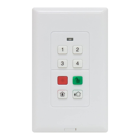
Vivint VS-KPAD01-001 User manual

Ins
tallation Instructions
You
can securely install (mount) the keypad with the provided screws.
To mount with the provided screws
:
1. Slide the battery cover / mounting plate down and remove it.
2. Place the mounting plate in the desired location.
3.
Secure the mounting plate with the 2 screws, using the slotted hole to adjust the plate
up or down to ensure a precise level.
4. Reattach the keypad by placing it directly on the mounting plate, and sliding it down
until it locks into place.
Adding the Keypad to the
System — Network Inclusion
Add the keypad device to the Vivint system using one of the following methods
below.
•Vivint app (SmartStart Inclusion):Scan the SmartStart QR code on the box with your
smartphone, and then follow the prompts in the app. (Note: The QR code can also be found
inside the battery cover under the batteries.)
SmartStart enabled products can be added into a
Z-Wave network by scanning the Z-Wave QR code present on the product with a controller
providing SmartStart inclusion. No further action is required and the SmartStart product will
be added automatically within 10 minutes of being switched on in the network vicinity.
•Vivint panel/hub via Z-Wave (Classic Inclusion): Use this standard method for adding Z-Wave
devices at the panel or hub. Use the "PAIR/RESET" button next to the battery tray. Follow the
onscreen prompts to add the keypad.
Removing the Keypad from the System — Network Exclusion
To remove
the keypad device from the Vivint system, follow the procedure below.
•Vivint panel/hub via Z-Wave: Use this standard method for excluding Z-Wave devices at the panel or hub. Use the "PAIR/RESET"
button next to the battery tray. Follow the onscreen prompts to remove the keypad.
The
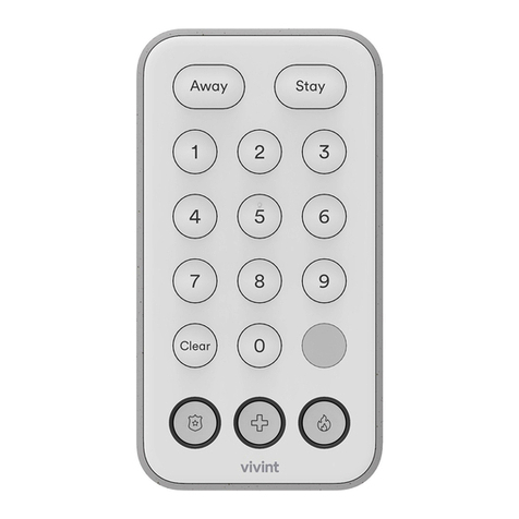
Vivint Keypad is a wireless Z-Wave™ control device that provides remote access to the security
features for a Vivint Smart Home
™ system, including enabling and disabling both the Arm Away and Arm
Stay security modes.
The keypad can also be used to transmit a signal to Vivint Monitoring for
fire, panic, and emergency
conditions such as a home intrusion.
The keypad has an easy
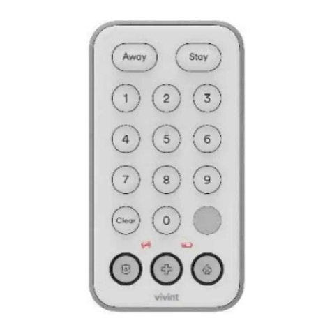
-to-use interface with identified and illuminated buttons, as well as indicator icons
that show when the device is offline, or battery power is low. It also
displays security system status with a
downcast
indicator light.
This document includes a product description,
illustrations, installation instructions, basic system
operation
/ user functionality, as well as technical specifications, standards listings, and regulatory
compliance
references. Note: For supplementary use only.
(
NOTE: The Vivint Keypad is for supplementary use only, and is not intended to be used as the primary
user interface. To access installation instructions, refer to
the Vivint Support site: support.vivint.com.)
Vivint
Keypad
(V
S-KPAD01-001)
Quick Reference (User Manual – Installation & Operation)
PRINT INSTRUCTIONS:
REFERENCE SHEET VS-KPAD01-001 P/N 77-600046-001 REV 1.0 |
INK: BLACK | MATERIAL: 20 LB MEAD BOND | SIZE: 8.50" X 11.00" SCALE 1:1 |
FOLDS: BI-FOLD VERTICAL, BI-FOLD HORIZONTAL (TO FIT IN BOX)
Keypad (back view, open;
battery cover / mounting plate off) —
Keypad (front view) —
4931 N 300 W Provo, UT 84604
Basic Operation / User Functionality
Once the keypad is up and running, the user can perform the following functions. For more details,
refer to online Help at the
Vivint Support site: support.vivint.com.
MAIN FEATURES
—
•
Arm to STAY mode (press & hold the button for at least 5 seconds or until the system is armed)
•
Arm to AWAY mode (press & hold the button for at least 5 seconds or until the system is armed)
•
Disarm the system (enter a valid user's 4-digit PIN code)
•
NOTE: The keypad will beep 3 times when arming (Stay or Away), and 2 times when disarming.
Additionally, the keypad will beep every 3 seconds (speeding up for the final 10 seconds) during
the Exit Delay countdown.
•
Send an emergency signal to Vivint Monitoring (press & hold the PANIC, FIRE, or EMERGENCY
button for 2 seconds)
•
Verify system status by viewing the LED downcast light (see colors below). By default the keypad
wakes-on-motion via its proximity sensor – this setting can be disabled, requiring a button press
to wake – whereupon the downcast light, and any buttons applicable to the current security
status, will illuminate for 5 seconds.
Green:System disarmed (ready to arm)
Orange:System armed
Red:Alarm in progress

Testing
Before i
nstalling the keypad, verify that the mounting location provides reliable RF communication to the panel. To verify:
1. Press and hold the STAY button until the countdown is complete.
2. Confirm that the security hub has transitioned into Armed Stay mode.
3. Enter your PIN from the keypad, and confirm on the hub that the system has successfully been disarmed.
NOTE: Test the system at least once a year to ensure proper functionality.
FCC and ISED Canada Regulatory Compliance Declarations*
CAUTION!
Unauthorized changes or modifications could void the user’s authority to operate the equipment.
This device has been tested and found to comply with the limits for a Class B digital device, pursuant to Part 15 of FCC Rule
s and Industry Canada license-exempt RSS
standard(s). Operation is subject to the following two conditions:
(1) This device may not cause harmful interference, and
(2) This device must accept any interference received, including interference that may cause undesired operation of the device.
These limits are designed to provide reasonable protection against harmful interference in a residential installation. This e
quipment generates, uses, and can radiate radio
frequency energy and, if not installed and
used in accordance with the instructions, may cause harmful interference to radio communications. However, there is no guaran
tee
that interference will not occur in a particular installation. If this equipment does cause harmful interference to radio or
television reception, which can be determined by
turning the equipment off and on, the user is encouraged to try to correct the interference by one or more of the following m
easures:
•Reorient or relocate the receiving antenna.
•Increase the separation between the equipment and the receiver.
•Connect the equipment into an outlet on a circuit different from that to which the receiver is connected.
•Consult the dealer or an experienced radio/television technician for help.
FCC ID:
2AAAS-KP01
IC:
10941A-KP01
*For
complete regulatory compliance information, go to: support.vivint.com/fcc
© 2021 Vivint Inc. All Rights Reserved.| www.vivint.com | 1-800-216-5232 | Device M/N: KP01 | Doc P/N: 77-600046-001 Rev. 1.0
Battery Installation and Replacement
Use only the recommended batteries (see
Specifications). To install or replace the batteries:
1. Remove the keypad from the mounting plate (see Installation Instructions).
2. Lift the old batteries out by hand.
3. Insert the replacement batteries with the "+" sign facing out.
4. Verify keypad operation, configuration, and RF communication with the panel.
BATTERY CAUTIONS
!Always use new alkaline batteries. Do not use rechargeable batteries of any type (they will not operate the device properly and may lead to damage).
Do not mix old and new batteries. Do not mix battery types, for example
lithium with alkaline. Dispose of batteries properly in accordance with local regulations.
Do not dispose
of batteries in fire
(batteries may explode or leak).If you are leaving your home for a month or more, you should replace the batteries as a precaution against battery failure in
your absence.
Always replace the batteries as soon as the
low battery indicator goes on. The keypad is a battery-powered device; you should replace the batteries before they run out.
Always
replace the batteries once a year, even if the indicator does not
go on. Replacing the batteries also helps to prevent leakage that can corrode and damage the device.
Specifications
Wireless Signal Range
Up to 100 m
Code Outputs
Key press 0-9; STAY; AWAY; CLEAR, FIRE; PANIC; EMERGENCY; Supervisory; Low Battery
Transmitter Frequency
908.42 MHz / 916 MHz (crystal controlled)
Transmitter Frequency Tolerance
< 25 KHz
Transmitter Bandwidth
< 100 KHz
Modulation Type
FSK / GFSK
Unique ID Codes
Over one (1) million different code combinations
Peak Field Strength
Typical 93 uV/m at 3m
Dimensions (WxHxD)
5.91 x 3.15 x 1.05 in. (15.0 x 8.0 x 2.6 cm)
Weight (incl battery & bracket)
7.69 oz. (218 g)
Housing Material
ABS plastic
Color
Gray and white
Operating Temperature
32° to 120° F (0° to 49° C)
Relative Humidity
5-95% Non-Condensing
Batteries
Four (4) 1.5V AAA alkaline batteries, or equivalent Lithium batteries
Battery Life
1 year under normal usage
Regulatory Listing(s)
cULus, FCC Part 15 Class B, ISED, for Indoor Residential Use Only
Z-Wave Alliance
ZC12-21030206
Warranty*
30 months from date of manufacture
Included Accessories
Two (2) Phillip's head screws; two (2) plastic wall anchors; double-sided tape
Factory Default
Reset
To restore the keypad
device to its factory default settings, follow the procedure below. (NOTE: Resetting the keypad removes it from any connected networks.
U
se this procedure only when the network primary controller is missing or otherwise inoperable.)
1. Locate the button labeled PAIR/RESET next to the battery tray.
2. Insert a paperclip into the hole until you feel the button depress.
3. Hold the button down for ten seconds. The green downcast indicator light
will blink rapidly while the reset button is pressed and go out after ten seconds.
4. The downcast light will turn red when the reset operation is complete. The device is now ready to be added back to a Z-Wave network.
Table of contents
Other Vivint Keypad manuals
Popular Keypad manuals by other brands

Macally
Macally BTNUMKEY user manual
Assa Abloy
Assa Abloy KP10G77 installation instructions
DMP Electronics
DMP Electronics 7872 quick start guide

Comtech EF Data
Comtech EF Data KP-10 Installation and operation manual
jcm-tech
jcm-tech BLUE PAD user manual
Crestron
Crestron HTT-B10EX Operations & installation guide
