Vivo Link VLMC101-H User manual
ADVARSEL!
Dette beslag skal være forsvarligt fastgjort til loftet. Hvis beslaget ikke er
monteret korrekt, kan det resultere i at projektoren kan falde ned og even-
tuelt beskadige personer eller udstyr.
Bemærk: De skruer og beslag, der følger med denne indpakning, er ikke beregnet til montering i
gibsloft, og du bedes derfor kontakte den lokale isenkræmmer for vejledning om hvilket tilbehør, som
egner sig bedst til dette formål.
Nødvendigt værktøj • 4 mm træbor • 8 mm betonbor • Stjerneskruetrækker
INSTALLATIONSVEJLEDNING
VLMC101-H
Udpakningsinstruktioner
Åben indpakningen forsigtigt og læg indholdet på et stykke pap eller en anden beskyttende over-
ade for at undgå beskadigelse. Kontroller at pakkens indhold stemmer overens med tilbehørs-
oversigten på næste side. Kontroller også om de medfølgende komponenter er modtaget ube-
skadiget. Brug ikke beskadigede eller defekte dele.
Vigtige sikkerhedsoplysninger
Montér og brug dette beslag med varsomhed. Læs venligst vejledningen inden påbegyndelse
af montering og følg nøje alle instruktioner. Benyt passende sikkerhedsudstyr under montering.
Kontakt venligst en kvaliceret håndværker for hjælp hvis du ikke forstår vejledningen eller er i
tvivl om sikkerheden ved montering. Hvis du er i tvivl om din loftkonstruktion bedes du konsul-
tere en kvaliceret installatør.
Brug ikke dette produkt til andre formål, eller i andre kongurationer end de udtrykkeligt angivne
i denne vejledning. Vi fraskriver os hermed ethvert ansvar eller skade som følge af forkert monte-
ring eller forkert brug af dette produkt.
1
DANSK

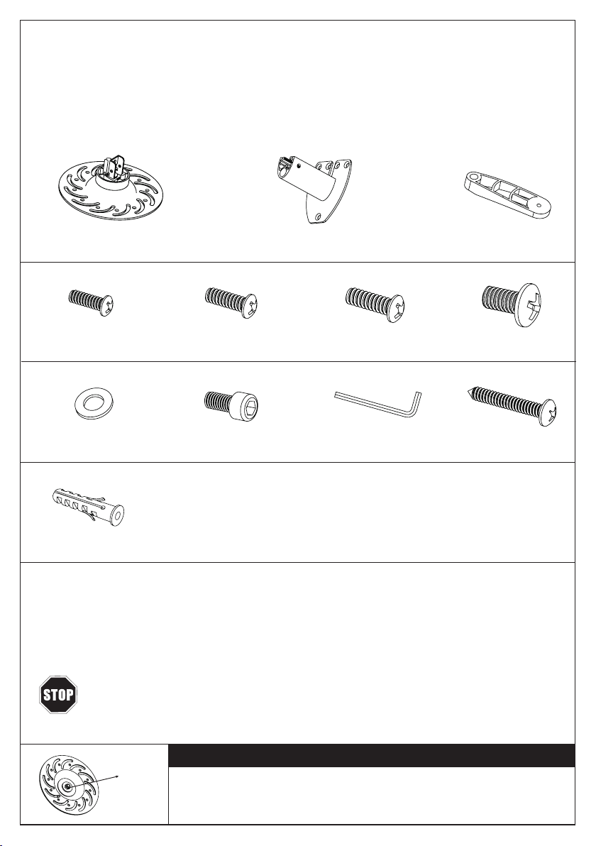
(1) Universal Bundplade – a (1) Loftbeslag – b (4) Beslag arm – c
(3) Rawlplugs - j
(4) M3x16 Bolt - d (4) M4x12 Bolt - e (4) M5x12 Bolt - f (4) M6x12 Bolt - g
(4) M3/M4 Spændeskive - h (6) M6x16 Umbraco Bolt - i (1) Umbraconøgle - j (3) Skrue - k
Vælg de rigtige monteringsdele
1. Vend projektoren og nd fastgørelsespunkterne
2. Test vær enkelt skruestørrelse
3. De korrekte skruer skal passe til fastgørelsespunktet, og må ikke falde ud ved belastning/tryk
MONTERINGSSKRUERNE MÅ IKKE OVERSPÆNDES MOD PROJEKTORENS
KABINET. BRUG AF FORKERT SKRUEDYBDE KAN BESKADIGE DIN PROJEKTOR.
VIGTIGT
Du kan spænde denne møtrik, alt efter hvor meget du vil vippe/tilte
projektoren. Men vær forsigtig med at overspænde møtrikken, da
der i så fald kan opstå problemer med vippe-/tiltfunktionen.
møtrik
TILBEHØRSOVERSIGT
DANSK
2

Montering af beslag arme på projekteren
d (h), e (h), f, g 1. Find fastgørelsespunkterne på undersiden af projektoren.
2. Fastgør det korrekte antal arme (c) til projektoren ved hjælp af de
medfølgende bolte (d (h), e (h), f, g).
3. Stram endnu ikke boltene helt.
4. Hvis du benytter M3/M4 boltene, skal du huske at bruge M3/M4
spændeskiverne (h).
Montering af universal bundplade på beslag armene
1. Tilpas universal bundpladen til beslag armene.
2. Placer armene for bedst mulig konguration. Det kan være
nødvendigt at hejse eller sænke hver enkelt arm individuelt.
3. Fastgør armene til universal bundpladen ved at skrue M6x16
umbraco bolte (i) på beslag armene ved hjælp af den
medfølgende umbraconøgle (j). Husk ikke at overspænde
boltene.
Montering af loftbeslag i loftet
Benyt loftbeslaget (b) som en skabelon til at markere de steder, hvor
de 3 huller i loftet skal placeres. Forbor disse huller med et 8 mm
betonbor til mindst 50 mm i dybden. Indsæt rawlplugs (l) i hvert hul.
Sørg for, at rawlplugsene sidder helt plant med betonoveraden.
Fastgør loftbeslaget til loftet ved hjælp af de 3 skruer (k).
Betonloft
Træloft
Benyt loftbeslaget (b) som en skabelon til at markere de steder, hvor
de 3 huller i loftet skal placeres. Forbor disse huller med et 4 mm
træbor til mindst 50 mm i dybden. Fastgør loftbeslaget til loftet ved
hjælp af de 3 skruer (k).
Step 1
Step 2
Step 3
DANSK
4mm
3
i
a

Montering af loftbeslag til universal bundpladenStep 4
Fastgør loftbeslaget (b) til universal bundpladen (a)
ved hjælp af de 2 M6x16 umbraco bolte (i) som vist
på tegningen. Spænd op med den medfølgende
umbraconøgle (j).
TAK FORDI DU HAR VALGT ET AF VORES PRODUKTER
DANSK
4

INSTALLATION INSTRUCTION
VLMC101-H
CAUTION!
This projector mount must be securely attached to the ceiling. If the mount is
not properly installed it may fall, resulting in possible injury and/or damage.
Note:The mounting components and hardware supplied in this package are not designed for installa-
tions to ceiling with steel studs or to cinder block. If the hardware you need for your installation is not
included, please consult your local hardware store for proper mounting hardware for the application.
Tools Required • 4mm Drill Bit • 8mm Masonry Bit • Philips Screwdriver
Unpacking Instructions
Carefully open the carton, remove contents and lay out on cardboard or other protective surface
to avoid damage. Check package contents against the Supplied Parts List in the next page to
assure that all components were received undamaged. Do not use damaged or defective parts.
Important Safety Information
Install and operate this device with care. Please read this instruction before beginning the instal-
lation, and carefully follow all instructions contained herein. Use proper safety equipment during
installation. Please call a qualied installation contractor for help if you don’t understand these
directions or have any doubts about the safety of the installation. If you are uncertain about the
nature of your ceiling, consult a qualied installation contractor.
Do not use this product for any purpose or in any conguration not explicitly specied in this
instruction. We hereby disclaims any and all liability or damage arising from incorrect assembly,
incorrect mounting, or incorrect use of this product.
ENGLISH
5
(1) Projector Plate – a (1) Ceiling Plate with tube assembled – b (4) Mounting Legs – c
(3) Rawlplugs - j
(4) M3x16 Bolt - d (4) M4x12 Bolt - e (4) M5x12 Bolt - f (4) M6x12 Bolt - g
(4) M3/M4 Washer - h (6) M6x16 Hexangular Head Bolt - i (1) Allen Wrench - j (3) Philips Screw - k
Selecting the Proper Mounting Hardware
1. Invert the projector and locate the mounting points
2. Test each size of the screws provided
3. The correct screws should thread easily into the mounting point and not pull out when pressure
is applied
DO NOT OVER-TIGHTEN YOUR MOUNTING SCREWS TO THE PROJECTOR CHASIS.
USING THE INCORRECT SCREW DEPTH MAY CAUSE DAMAGE TO YOUR PROJECTOR.
ATTENTION
You can tighten this nut if you want to make the big tilting for your
projector. But please don’t over-tighten, otherwise you may have
problem to do the tilting.
nut
SUPPLIED PARTS LIST
ENGLISH
6

1. Locate the mounting points on the bottom of the projector.
2. Attach the appropriate number of Mounting Legs (c) to the projector
using the appropriate mounting Bolts (d (h), e (h), f, g).
3. Do not tighten these bolts completely at this time.
4. The M3/M4 Washers (h) have to be used if you use the M3/M4 bolts.
1. Align the Projector Plate (a) to the mounting legs.
2. Position the legs accordingly for best conguration. You may raise or
lower each leg independently.
3. Secure the legs to the projector plate by screwing M6x16 Hexangular
Head Bolt (i) (do not over-tighten) on the mounting legs, using the
Allen Wrench (j) provided.
4. Tighten all bolts at this time.
d (h), e (h), f, g
Use the Ceiling Plate (b) as a template to mark 3 hole locations on
the ceiling. Pre-drill these holes with a 8mm masonry bit to at least
50mm in depth. Insert a Rawlplugs (l) into each of these holes. Make
sure the rawlplugs is seated completely ush with the concrete
surface. Attach the ceiling plate to the ceiling using 3 Philips Screws
(k) and 3 Rawlplugs (l).
Use the Ceiling Plate (b) as a template to mark 3 hole locations on
the ceiling. Pre-drill these holes with a 4mm drill bit to at least
50mm in depth. Attach the ceiling plate to the ceiling using the
3 Philips Screws (k).
Install the Mounting Legs on the ProjectorStep 1
Install the Projector Plate to the Mounting LegsStep 2
Install the Ceiling Plate to the CeilingStep 3
Concrete Ceiling
Wood Stud Ceiling
ENGLISH
7
i
a

THANKS FOR CHOOSING ONE OF OUR PRODUCTS
Connecting the Aluminum Tube (b) and Projector Plate (a)
by 2 M6x16 Hexangular Head Bolts (i) as the picture,
tighten by Allen Wrench (j) provided.
Connecting the Aluminum Tube to Projector PlateStep 4
ENGLISH
8
Table of contents
Languages:
Other Vivo Link Projector Accessories manuals


