Vivo Link VL120020 User manual

VL120020
4K Home Distribution Hub
User Manual

4K Home Distribution Hub
Preface
Read this user manual carefully before using this product. Pictures shown in this
manual is for reference only, different model and specifications are subject to real
product.
This manual is only for operation instruction only, not for any maintenance usage.
Trademarks
Product model and logo are trademarks. Any other trademarks mentioned in this
manual are acknowledged as the properties of the trademark owner. No part of this
publication may be copied or reproduced without the prior written consent.
FCC Statement
This equipment generates, uses and can radiate radio frequency energy and, if not
installed and used in accordance with the instructions, may cause harmful interference
to radio communications. It has been tested and found to comply with the limits for a
Class B digital device, pursuant to part 15 of the FCC Rules. These limits are designed
to provide reasonable protection against harmful interference in a commercial
installation.
Operation of this equipment in a residential area is likely to cause interference, in which
case the user at their own expense will be required to take whatever measures may be
necessary to correct the interference
Any changes or modifications not expressly approved by the manufacture would void
the user’s authority to operate the equipment.

4K Home Distribution Hub
SAFETY PRECAUTIONS
To insure the best from the product, please read all instructions carefully before using
the device. Save this manual for further reference.
Unpack the equipment carefully and save the original box and packing material for
possible future shipment
Follow basic safety precautions to reduce the risk of fire, electrical shock and injury
to persons.
Do not dismantle the housing or modify the module. It may result in electrical shock
or burn.
Using supplies or parts not meeting the products’ specifications may cause
damage, deterioration or malfunction.
Refer all servicing to qualified service personnel.
To prevent fire or shock hazard, do not expose the unit to rain, moisture or install
this product near water.
Do not put any heavy items on the extension cable in case of extrusion.
Do not remove the housing of the device as opening or removing housing may
expose you to dangerous voltage or other hazards.
Install the device in a place with fine ventilation to avoid damage caused by
overheat.
Keep the module away from liquids.
Spillage into the housing may result in fire, electrical shock, or equipment damage.
If an object or liquid falls or spills on to the housing, unplug the module immediately.
Do not twist or pull by force ends of the optical cable. It can cause malfunction.
Do not use liquid or aerosol cleaners to clean this unit. Always unplug the power to
the device before cleaning.
Unplug the power cord when left unused for a long period of time.
Information on disposal for scrapped devices: do not burn or mix with general
household waste, please treat them as normal electrical wastes.

4K Home Distribution Hub
Contents
1. Introduction.................................................................................................................1
1.1 Brief Introduction ...............................................................................................1
1.2 Features ............................................................................................................1
1.3 Package List......................................................................................................2
2. Product Appearance ...................................................................................................3
2.1 4K HDBaseT Matrix Switcher............................................................................3
2.2 HDBaseT Receiver............................................................................................4
3. System Connection.....................................................................................................6
3.1 System Applications ..........................................................................................6
3.2 Connection Diagram..........................................................................................6
3.3 Connection Procedure.......................................................................................7
3.4 Connection with HDBaseT Receiver..................................................................7
4. System Operations .....................................................................................................9
4.1 IR Control ..........................................................................................................9
IR Remote Description ............................................................................9
Usage of IR Remote..............................................................................10
4.1.2.1. Switching I/O connection............................................................10
4.1.2.2. EDID Management.....................................................................10
4.1.2.3. Clear operation...........................................................................11
Force Carrier .........................................................................................11
Control Far-end Device locally...............................................................11
Control Local Device Remotely .............................................................12
4.2 RS232 Control.................................................................................................14
RS232 connection.................................................................................14
Installation/uninstallation of RS232 Control Software............................14
Basic Settings........................................................................................14
RS232 Communication Commands ......................................................15
4.3 TCP/IP Control.................................................................................................22
Control Modes.......................................................................................22
GUI for TCP/IP control...........................................................................23
GUI Update............................................................................................26

4K Home Distribution Hub
4.4 Firmware Update via USB...............................................................................27
5. Specification .............................................................................................................28
5.1 4K HDBaseT Matrix Switcher..........................................................................28
5.2 HDBaseT Receiver..........................................................................................29
6. Panel Drawing ..........................................................................................................30
6.1 4K HDBaseT Matrix Switcher..........................................................................30
6.2 HDBaseT Receiver..........................................................................................30
7. Troubleshooting & Maintenance ...............................................................................31
8. After-sales Service....................................................................................................33

4K Home Distribution Hub
1
1. Introduction
1.1 Brief Introduction
This product is a professional 4K HDBaseT Home Distribution Hub Kit, which consists
of a 4K HDBaseT Matrix Switcher, 3 HDBaseT Receivers and accessories.
The 4K HDBaseT Matrix Switcher is a professional 4x4 HDBaseT Matrix Switcher that
consist of the following inputs and outputs, 4 HDMI IN (4kx2K@60Hz signal at max), 3
IR IN, 1 IR EYE, 4 IR OUT, 3 HDBaseT OUT, 1 HDMI OUT, 1 SPDIF OUT, 1 L&R RCA
OUT, and TCP/IP, RS232 control port via phoenix connector.
The HDBaseT Receiver is an HDBaseT Receiver that consists of the following inputs
and outputs, 1 HDBaseT IN, 1 IR IN, 1 IR OUT and HDMI OUT. The receiver is
powered directly by the Matrix Switcher.
All HDMI inputs can be selected by either the front panel buttons, IR, RS 232 or GUI.
The selected source is delivered to HDBaseT zoned outputs 1~3 & HDMI Output.
The Matrix Switcher is capable of delivering 4K signals up to 40m, 1080p up to 70m
and powering the receivers via a single CAT5e cable. It is however recommended to
use good quality CAT6 cable.
The Matrix Switcher supports EDID management and is HDCP 2.2, 1.4 compliant.
Audio sources can be selected via RS232 commands and TCP/IP at the Matrix
Switcher or by 3rd Party control.
1.2 Features
Support HDMI1.4 & HDCP2.2, and compliant with lower standards, capable to
transmit 4Kx2K@60Hz 4:2:0 & 1080p 3D
Support manual HDCP management and auto-detecting
Transmit 4Kx2K signal for 8m via HDMI port, 40m via HDBT port
Audio source selectable via RS232 command
3 HDBaseT outputs, distances up to 70m at 1080p and 40m at 4Kx2K on a single
CAT5e/6 cable can be achieved.
The HDBaseT Receivers are powered by the matrix switcher 12VDC by PoC
technology.
LED indicators show real-time switching status.
Controllable via front panel, RS232, IR and TCP/IP
Support bi-directional IR& RS232 control
Built-in GUI for TCP/IP control
Powerful EDID management

4K Home Distribution Hub
2
Support non-volatile memory [NVM] for reliable operation.
Support firmware upgrade through Micro USB port
Easy installation with rack-mounting design
1.3 Package List
1 x 4K HDBaseT Matrix Switcher,
3 x HDBaseT Receivers
1 x Power Adapter (DC 24V 2.71A)
1 x Power Cord(Optional)
4 x IR Emitters(Optional)
3 x IR Receivers(Optional)
1 x IR Receiver(Inserted into IR EYE port)
1 x IR remote
1 x RS232 cable(Phoenix to 9-pin D-Sub)
2 x Mounting ears & 6 x Screws (For 4K HDBaseT Matrix Switcher )
6 x Mounting ears & 6 x Screws (For HDBaseT Receiver)
4 x Trapezoidal Plastic pads (For 4K HDBaseT Matrix Switcher)
12 x Round Plastic pads(For HDBaseT Receiver)
1 x User manual
Notes: Confirm if the product and the accessories are all included, if not, please
contact with the dealers.
4K Home Distribution Hub
3
2. Product Appearance
2.1 4K HDBaseT Matrix Switcher
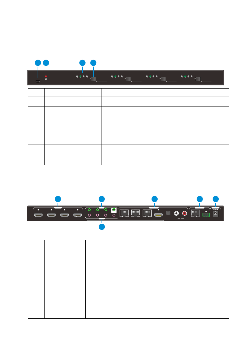
1. Front Panel
No.
Name
Description
①
FIRMWARE
Micro USB port for updating firmware
②
Power Indicator
OFF: No power;
RED: DC power present or Standby Mode
③
INPUT selector
Indicators
Total 4 groups, and each group is set up including 4
green indicators for 4 input sources, numbered from
"1" to "4".
④
Output selector
button
Total 4 output selector buttons, press the buttons to
switch input cycle for the output.
Notes: Pictures shown in this manual are for reference only, different model and
specifications are subject to real product.
2. Rear Panel
No.
Name
Description
①
HDMI INPUTS
4 x HDMI input ports, type Afemale HDMI connector,
connect the Source with an HDMI cable to any of the
HDMI inputs.
②
IR IN
3 x IR IN: Connect with IR receiver, fixed IR input
for the output, cannot be switched separately. It
makes up an IR bi-directional transmission with the
IR OUT on the corresponding HDBaseT receiver.
1 x IR EYE: Connect with extended IR receiver, use
the IR remote to control the Matrix Switcher.
③
IR OUT(1~4)
Plug in the IR Emitter and attach to the front of the Source.
OUTPUT 1
INPUT TO
1 2 3 4
OUTPUT 2
INPUT TO
1 2 3 4
OUTPUT 3
INPUT TO
1 2 3 4
OUTPUT 4
INPUT TO
1 2 3 4
FIRMWARE
12 3 4
HDMI 1 HDMI 2 HDMI 3 HDMI 4 1-HDBT
IR OUT
IR EYE
2-HDBT 4-SPDIF4-HDMI
3-HDBT L R4 DC 24VTCP/IP
RxTx
RS232
POWERCONTROLIR IN OUTPUTSINPUTS 1 2 3
41 2 3
1245 6
3

4K Home Distribution Hub
4
This then emits the IR signal received from the HDBaseT
Receiver. There are 4 IR OUTPUT sockets marked on IR
matrix.
④
OUTPUTS
HDBaseT: The HDBT RJ45 outputs deliver HD video,
Audio and PoC to the HDBaseT Receiver up to 70m.
HDMI: Connect an HDMI cable from the Matrix
Switcher to the displayer.
SPDIF: Digital audio output connects directly via an
optic fibre cable to the Toslink input on a sound bar.
RCA (L&R): PCM Analogue audio output sockets
connect the de-embedded audio additional speakers.
⑤
Control
TCP/IP: RJ45 port. Connect with PC for Web-based
GUI control.
RS232: Serial port for unit control, 3-pin pluggable
terminal block, connects with control device (e.g.
PC).
⑥
DC 24V
Connect with DC24V 2.71A power adaptor.
Note: Pictures shown in this manual are for reference only, different model and
specifications are subject to real product.
2.2 HDBaseT Receiver
1. Front Panel
No.
Name
Description
①
HDMI OUT
Connect to HDMI display.
②
IR IN
Plug in the IR receiver, this will receive the IR signals from the RCU
and send through to the Matrix Switcher and then control the
desired source.
③
IR OUT
Plug in the IR emitter and attached to the fornt of the display, this
will send the IR signals form the Matrix Switcher to control the
display which is connected to the HDMI OUT port.
IR IN IR OUTHDMI OUT
123

4K Home Distribution Hub
5
2. Rear Panel
No.
Name
Description
①
Power
Indicator
OFF: No power;
RED: DC power present (PoC).
②
TP IN
The RJ45 socket has two LED status indicators. Plug in the Pre-
installed CAT cable in to the HDBT RJ45 socket.
HDCP: HDCP compliant indicator
OFF: No HDMI traffic (no picture)
GREEN: Signals with HDCP.
Blinking GREEN: Signal without HDCP
LINK: HDBT Link status indicator.
OFF: No Link
YELLOW:Link Successful
Blinking YELLOW: Link Error
TP IN
LINK HDCP
12

4K Home Distribution Hub
6
3. System Connection
3.1 System Applications
The new 4K Home Distribution Hub Kit is designed for the residential market delivering
HD Video,Audio to 4 zones with total control and simplicity.
Usage Precautions:
1) The 4K Home Distribution kit should be installed in a clean and dust free
environment.
2) Ensure that all plugs, power cords and sockets are in good condition without signs
of damage.
3) All devices should be connected before power on.
3.2 Connection Diagram
VCR
STB
DVD
HDBaseT Receiver
IR Emitter
IR Emitter
AVR Amplifier
Laptop
HDTV
HDTV
PC
Speaker
Speaker
MatrixSwitcher

4K Home Distribution Hub
7
3.3 Connection Procedure
1) Connect HDMI sources (e.g. DVD) to HDMI input ports of the Matrix Switcher via
good quality HDMI cables.
2) Connect the Pre-Installed CAT5e/CAT 6 cable infrastructure to Matrix Switcher
and HDBaseT receivers via good quality patch leads.
3) Connect HDTV to HDMI output port via HDMI cable.
4) Plug in an HDMI cable in to each of HDBaseT Receiver and connect to the local
display [HDTV].
5) Connect AVR amplifier to SPDIF output port or via the Toslink optic fibre cable.
6) Connect speaker to L&R (RCA) output port via audio cable.
7) Plug the IR Receivers 3.5mm jack into the IR IN sockets on HDBaseT Receivers
and plug in the IR Emitters to the IR OUT sockets (1~4) on Matrix Switcher to
make up as IR Matrix.
8) Plug the phoenix connector in to the RS232 socket on the matrix, this will enable
the Matrix Switcher to be controlled via a PC.
9) Plug in a Patch lead from the router in to the Ethernet port on Matrix Switcher to
control Matrix Switcher by TCP/IP protocol.
10) Plug in the Power supply adapter 24V DC and tighten to secure. Once all
components have been connected and the installation is completed, switch on the
mains supply at the socket.
Note:
1. Connect HDBT ports of Matrix Switcher and far-end HDBaseT Receiver with
straight-through cable.
2. IR receivers connected to IR IN should be with carrier. If not, send
command %0900. or %0901.to activate native carrier mode or force carrier mode
in the IR matrix launched between Matrix Switcher and far-end HDBaseT Receiver.
3.4 Connection with HDBaseT Receiver
The Matrix Switcher has 3 HDBaseT outputs which support PoC technology. Plug in the
4 RJ45 patch leads in to the HDBT outputs and connect to the pre-installed
infrastructure. Connect HDBaseT Receivers to the pre-installed cabling via additional
patch leads. Plug the power supply in to the power socket on the matrix, the HDBaseT
Receiver will be powered by the Matrix Switcher.

4K Home Distribution Hub
8
PoC
DC 24V HDBaseT Receiver(PoC)
4K Home Distribution Hub
9
4. System Operations
4.1 IR Control
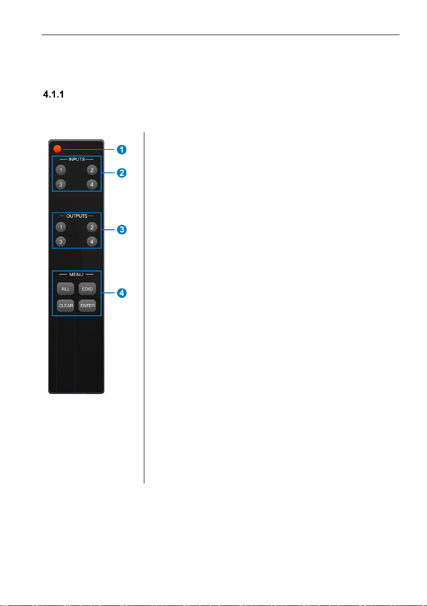
IR Remote Description
Connect an IR receiver to the IR EYE port of the Matrix Switcher, users can control it
through the included IR remote. Here is a brief introduction to the IR remote.
①Standby button, press it to enter/ exit standby mode.
②Input channels, range from 1~4, corresponding IR
signal switched synchronously when switching input
channels.
③OUTPUTS
In normal mode: output channel selection buttons.
In EDID invoking mode: press button 1/2 to switch
among the 5 embedded EDID data.
④Menu buttons: ALL, EDID, CLEAR and ENTER.
ALL: Select all inputs/ outputs.
EDID management button: Enable input port to
manually capture and learn the EDID data of
output devices.
CLEAR: Withdraw an operation like switching
output channel, learning EDID data before it
comes into effect. Meanwhile, the matrix will
return to the previous status.
ENTER: Confirm operation. Press and hold it for
3 seconds to enter in Inquiry mode.
Note: With this IR remote, the Matrix Switcher can be
controlled by the built-in IR, the extended IR receiver
connected to the IR EYE and the IR receiver on the far-end
receiver.
By using IR & HDBaseT transmission technology, the 4K Home Distribution Hub Kit has
some functions as follows:
1) Control far-end output device from local.
2) Control local input/output device remotely.
3) Control the Matrix Switcher locally/remotely.

4K Home Distribution Hub
10
Usage of IR Remote
4.1.2.1. Switching I/O connection
1. To convert one input to an output:
Example: Input 1 to Output 3
→Press INPUTS 1 + OUTPUTS 3 + ENTER
NOTE:
Default status, on first boot up this matrix assigns the IR outputs to the
corresponding HDMI input, meaning, IR out 1 is directly associated to HDMI
input 1 and so on. When you switch an HDMI input to a different output, the
corresponding IR OUT will be switched synchronously to allow the IR
commands to be sent from the select zone back through the Matrix
Switcher to the source.
2. To convert an input to several outputs:
Example: Convert Input 2 to Output 3 and 4
→Press INPUTS 2 + OUTPUTS 3 + OUTPUTS 4 + ENTER
3. To convert an input to all outputs:
Example: Input 1 to all Outputs
→Press INPUTS 1 + ALL + ENTER
4.1.2.2. EDID Management
The 4K Home Distribution Hub Kit features EDID management that enables the Matrix
Switcher to learn the EDID of all sources and sink devices. The Matrix Switcher can
learn the EDID from any device or be programmed to assign an EDID to the mirror port
through EDID Invoking.
1. EDID Learning(from output):
One input port learns the EDID data of one output port:
Example: Input 2 learns EDID data from output 4
→Press EDID + INPUTS 2 + OUTPUTS 4 + ENTER
All input ports learn EDID data from one output port:
Example: all input ports learn EDID data from output 4
→Press: EDID + ALL + OUTPUTS4 + ENTER
2. EDID invoking:
There are five types of embedded EDID data. The chart below illustrated the detailed
information of the embedded EDID data:

4K Home Distribution Hub
11
No.
EDID Data
1
1080P 2D 2CH
2
1080P 3D 2CH
3
1080P 2D Multichannel
4
1080P 3D Multichannel
5
3840x2160 2D(30Hz)
Press and hold “EDID” for 3 seconds to enter EDID invoking mode. In this mode, use
output buttons 1/2 to switch among the 5 embedded EDID data. Then press “ENTER”
to confirm invoking.
Format: Press and hold “EDID” for 3 seconds, INPUT# +OUTPUT1/2 + ENTER.
Invoke embedded EDID data for one input:
Example: set the EDID data of input 2 to the fourth type of embedded EDID data
→Press EDID (hold for 3 seconds to enter in EDID setting status) + INPUTS 2 +
OUTPUTS1 or 2 + ENTER
4.1.2.3. Clear operation
When you switch output channel, learn EDID data, or set EDID data, press “Clear”
button to EXIT the operation before you press “ENTER” to carry it on. When you press
it, the Matrix Switcher will return to the previous status.
Force Carrier
a) Only if the IR receiver connected to HDBaseT receiver is with IR carrier, can the
received IR signal be transferred to IR OUT port of the Matrix Switcher.
b) Only if the IR receiver connected to the Matrix Switcher is with IR carrier, can the
received IR signal be transferred to IR OUT port of the Matrix Switcher.
If the IR receiver connected to HDBaseT receiver or the Matrix Switcher is without
an IR carrier signal, send the command “%0901.” to enter infrared carrier enforcing
mode, and then IR signal can be transferred to IR OUT port.
Control Far-end Device locally
Connect an IR receiver to IR IN on the Matrix Switcher, and use the IR Remote of far-
end device to control the device locally.
Connect an IR receiver with IR carrier to the IR IN port of the Matrix Switcher; users
can control far-end output displayer via its IR remote from local.
In that case, the IR signal is transferred via twisted pair. Only the corresponding IR
OUT port can emit control signals to the remote display.
See the figure below:

4K Home Distribution Hub
12
Control far-end device from Local
Note: The IR receiver connected to IR IN must be with IR carrier
Control Local Device Remotely
Connect IR receiver(s) to IR IN on far-end HDBT receiver(s), and IR Emitter(s) to IR
OUT port of the switcher, and use the IR Remote of local source to control the device
remotely.
1 to 1:
Connect an IR receiver to IR IN on far-end HDBT receiver, and an IR Emitter to IR
OUT port of the switcher. Use the IR Remote of local source to control the device
remotely. See below:
Control local device from remote
Note: Send command “%0901.” to enter infrared carrier enforcing mode if the IR
Receiver connected to IR IN of the receiver is not with carrier.
DVD
IR Remote
HDM I 2 H DMI 3 HDM I 4 1-H DBT
IR OUT
IR EY E
2-HDBT 4-SPDIF4-HDMI
3-HDBT L R4 DC 24 VTCP /IP
RxTx
RS232
POWERCONTROLIR IN OUT PUTSINP UTS 1 2 3
41 2 3
HDM I 1
IR Emitter
HDTV
Receiver
HDTV
IR IN IR OUTHDM I OUT
TP IN
LINK HDCP
IR Emitter
DVD
HDM I 2 HDM I 3 HDM I 4 1-HDBT
IR OU T
IR EY E
2-HDBT 4-SPDIF4-H DMI3-H DBT L R4 DC 24 VTCP /IP
RxTx
RS232
POW ERCON TROLIR IN OUT PUTSINP UTS 1 2 3
41 2 3
HDM I 1
HDTV
IR Remote
Receiver
HDTV
IR IN IR OUTHDMI O UT
TP IN
LINK HDCP

4K Home Distribution Hub
13
Multiple to Multiple: (IR Matrix)
The 4 “IR OUT” ports and the 3 “IR IN” ports on the far-end receivers make up a
4x3 IR matrix. See as below:
IR Matrix
The IR signal is sent by IR remote, then it is transferred to HDBaseT receiver, then to
corresponding zone of the matrix through the twisted pair, finally it is transferred to IR
OUT port and received by controlled device.
Switching Operation:
Sending command (reference to 4.3 RS232 Control): [x1]R[x2].
x1: Corresponding to the 4 IR OUT ports of the Matrix Switcher, the IR transmitter
connected to this port can be placed at IR receiving area of output device or the
Matrix Switcher itself.
x2: Corresponding to the zone (receive IR signal from HDBaseT receiver with IR IN
port connects with IR receiver) number of the Matrix Switcher.
→ Example: Send command “3R2.” to transfer IR signal received from zone 2 to IR
OUT port 3.
IR Emitter
DVD
1 2 3 4 HDTV
HDM I 2 HDMI 3 HDMI 4 1-HDBT
IR OU T
IR EY E
2-HDBT 4 -SPDI F4-HDM I3-H DBT L R4 DC 24 VTCP /IP
RxTx
RS232
POWERCON TROLIR IN OUT PUTSINP UTS 1 2 3
41 2 3
HDM I 1
Receiver 1
HDTV
IR IN IR OUTH DMI OUT
TP IN
LINK HD CP
Receiver 2
HDTV
IR IN IR OUTHD MI OUT
TP IN
LINK HD CP
Receiver 3
HDTV
IR IN IR OUTH DMI OUT
TP IN
LINK HD CP

4K Home Distribution Hub
14
4.2 RS232 Control
RS232 connection
Except the front control panel, the Matrix Switcher can be controlled by far-end
control system through the RS232 communication port. This RS232 communication
port is a 3-pin phoenix connector. User can use the RS232 cable (Phoenix to 9-pin
D-Sub) to connect the RS232 port to PC, see as below:
Installation/uninstallation of RS232 Control Software
Installation Copy the control software file to the computer connected with the
Matrix Switcher.
Uninstallation Delete all the control software files in corresponding file path.
Basic Settings
Firstly, connect the Matrix Switcher with an input device and an output device. Then,
connect it with a computer which is installed with RS232 control software. Double-click
the software icon to run this software.
Here we take the software CommWatch.exe as example. The icon is showed as
below:
The interface of the control software is showed as below:
PC
HDMI 2 HDMI 3 H DMI 4 1-HDBT
IR OUT
IR EY E
2-HDBT 4 -SPDIF4-H DMI3-H DBT L R4 DC 24VTCP /IP
RxTx
RS232
POWERCONTROLIR IN OUTPUTSINPUTS 1 2 3
41 2 3
HDMI 1

4K Home Distribution Hub
15
Please set the parameters of COM number, baud rate, data bit, stop bit and the parity
bit correctly, only then will you be able to send command in Command Sending Area.
RS232 Communication Commands
Note:
1) Please disconnect all the twisted pairs before sending command EDIDUpgrade[X].
2) In above commands, “[”and “]” are symbols for easy reading and do not need to be
typed in actual operation.
3) Please remember to end the commands with the ending symbols “.” and “;”.
4) Type the command carefully, it is case-sensitive.
Baud rate: 9600 Data bit: 8 Stop bit: 1 Parity bit: none
Command
Function
Feedback
Example
System Commands
/*Type;
Inquire the models information.
XXXXX
/%Lock;
Lock the front panel buttons on the
System Locked!
Monitoring area, indicates
whether the command
sent works.
Command Sending area
Parameter Configuration area
Table of contents
Other Vivo Link Switch manuals

Vivo Link
Vivo Link VLSW141H User manual

Vivo Link
Vivo Link VLSC262 User manual

Vivo Link
Vivo Link VL120000 User manual

Vivo Link
Vivo Link VLHUB121-MME User manual

Vivo Link
Vivo Link VL120002 User manual

Vivo Link
Vivo Link VL120014 User manual

Vivo Link
Vivo Link VLSC151H User manual

Vivo Link
Vivo Link VL120026 User manual
Popular Switch manuals by other brands


Omnitron Systems
Omnitron Systems RuggedNet 10GPoEBT/Mi quick start guide

Austin Hughes
Austin Hughes CyberView U802 user manual

green-i
green-i MRT16-WP Product guide

Black & Decker
Black & Decker Lights Out 90539953 instruction manual

Sun Microsystems
Sun Microsystems Secure Application Switch N1216 Release notes

PS Engineering
PS Engineering PMA6000 Installation and operation manual