Vivo Link VL120026 User manual
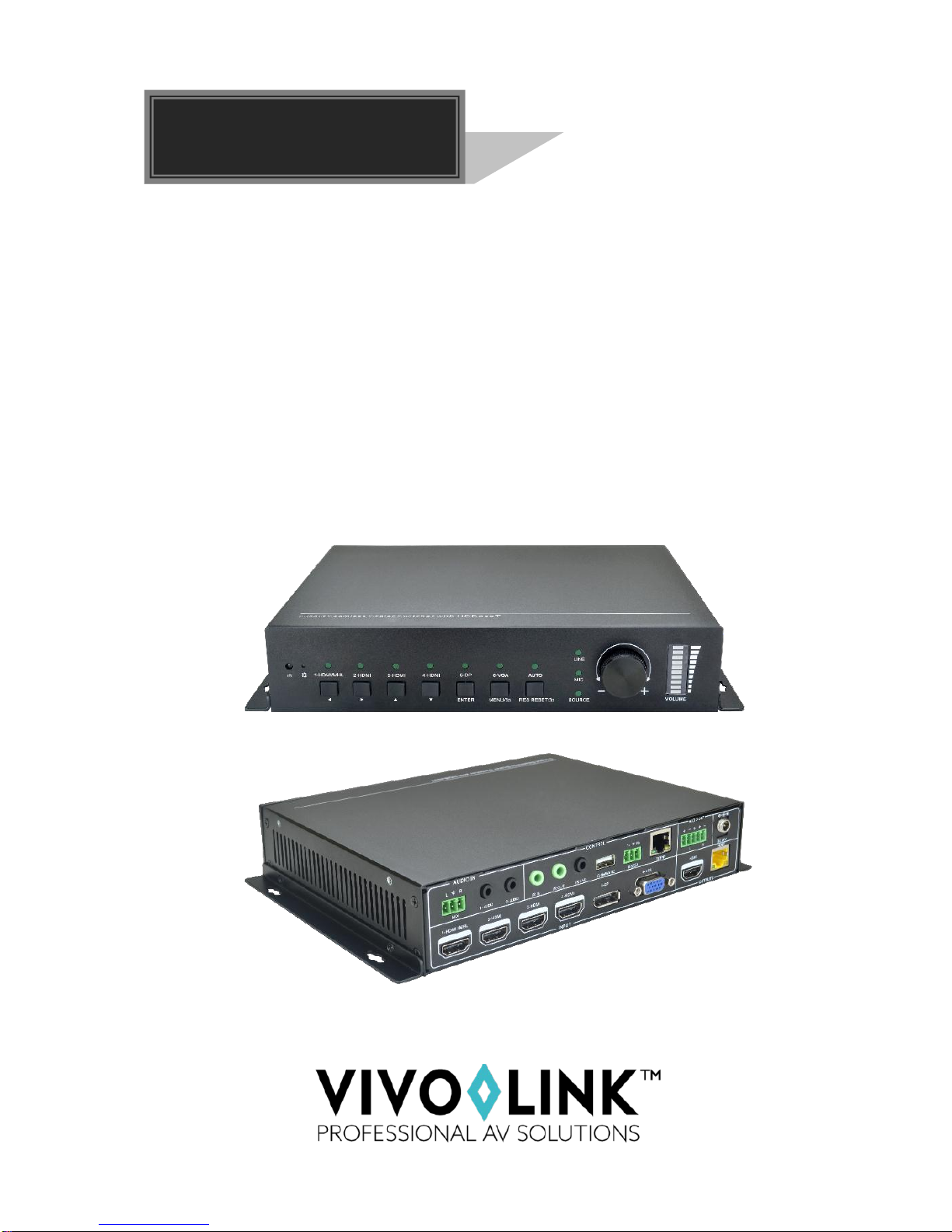
VL120026
6-input Seamless Scaler Switcher &
HDBaseT Receiver
User Manual

6-input Seamless Scaler Switcher & HDBaseT Receiver
Preface
Read this user manual carefully before using this product. Pictures shown in this manual
is for reference only, different model and specifications are subject to real product.
This manual is only for operation instruction only, not for any maintenance usage. The
functions described in this version are updated till May 2017. In the constant effort to
improve our product, we reserve the right to make functions or parameters changes
without notice or obligation. Please refer to the dealers for the latest details.
All product function is valid till 2017-5-3.
Trademarks
Product model, VivoLink are trademarks of EET Europarts A/S. Any other trademarks
mentioned in this manual are acknowledged as the properties of the trademark owner.
No part of this publication may be copied or reproduced without the prior written consent
of EET Europarts A/S.
FCC Statement
This equipment generates, uses and can radiate radio frequency energy and, if not
installed and used in accordance with the instructions, may cause harmful interference
to radio communications. It has been tested and found to comply with the limits for a
Class B digital device, pursuant to part 15 of the FCC Rules. These limits are designed
to provide reasonable protection against harmful interference in a commercial
installation.
Operation of this equipment in a residential area is likely to cause interference, in which
case the user at their own expense will be required to take whatever measures may be
necessary to correct the interference.
Any changes or modifications not expressly approved by the manufacture would void
the user’s authority to operate the equipment.

6-input Seamless Scaler Switcher & HDBaseT Receiver
SAFETY PRECAUTIONS
To insure the best from the product, please read all instructions carefully before using
the device. Save this manual for further reference.
Unpack the equipment carefully and save the original box and packing material for
possible future shipment
Follow basic safety precautions to reduce the risk of fire, electrical shock and injury
to persons.
Do not dismantle the housing or modify the module. It may result in electrical shock
or burn.
Using supplies or parts not meeting the products’ specifications may cause damage,
deterioration or malfunction.
Refer all servicing to qualified service personnel.
To prevent fire or shock hazard, do not expose the unit to rain, moisture or install this
product near water.
Do not put any heavy items on the extension cable in case of extrusion.
Do not remove the housing of the device as opening or removing housing may
expose you to dangerous voltage or other hazards.
Install the device in a place with fine ventilation to avoid damage caused by
overheat.
Keep the module away from liquids.
Spillage into the housing may result in fire, electrical shock, or equipment damage. If
an object or liquid falls or spills on to the housing, unplug the module immediately.
Do not twist or pull by force ends of the optical cable. It can cause malfunction.
Do not use liquid or aerosol cleaners to clean this unit. Always unplug the power to
the device before cleaning.
Unplug the power cord when left unused for a long period of time.
Information on disposal for scrapped devices: do not burn or mix with general
household waste, please treat them as normal electrical wastes.

6-input Seamless Scaler Switcher & HDBaseT Receiver
Contents
1. Introduction.................................................................................................................1
1.1 Brief Introduction ...............................................................................................1
1.2 Features ............................................................................................................1
1.3 Package List......................................................................................................2
2. Panel Description........................................................................................................3
2.1 Seamless Scaler Switcher.................................................................................3
2.2 HDBaseT Receiver............................................................................................5
3. System Connection.....................................................................................................7
3.1 Usage Precautions............................................................................................7
3.2 System Diagram................................................................................................7
3.3 Connection Procedure.......................................................................................7
4. Button Control.............................................................................................................9
4.1 Manual-Switching..............................................................................................9
4.2 Auto-Switching...................................................................................................9
4.3 Volume Adjusting...............................................................................................9
5. IR Control..................................................................................................................10
5.1 IR Remote .......................................................................................................10
5.2 Control Far-end Display Device.......................................................................11
5.3 Control Local Source Device...........................................................................11
5.4 CEC Function..................................................................................................12
6. RS232 Control..........................................................................................................14
6.1 RS232 Connection ..........................................................................................14
6.2 Installation/uninstallation of RS232 Control Software......................................15
6.3 RS232 Communication Commands ................................................................17
6.3.1 RS232 Control Mode Switching.............................................................17
6.3.2 Input Signal Switching...........................................................................17
6.3.3 Audio Adjusting......................................................................................18
6.3.4 VGA Scaling Configuration....................................................................20
6.3.5 Output Image Adjusting .........................................................................20
6.3.6 Auto Power-off Setup.............................................................................22
6.3.7 OSD Menu Control................................................................................23

6-input Seamless Scaler Switcher & HDBaseT Receiver
6.3.8 CEC Input Commands...........................................................................24
6.3.9 CEC Output Commands........................................................................24
6.3.10 EDID Configuration..............................................................................25
6.3.11 HDCP Compliance...............................................................................26
6.3.12 Device Setup.......................................................................................26
7. OSD Menu Control ...................................................................................................28
7.1 OPTIONS ........................................................................................................28
7.2 PICTURE.........................................................................................................29
7.3 SETUP.............................................................................................................30
8. Web-based GUI Control............................................................................................31
8.1 Control Menu...................................................................................................31
8.2 Configuration Menu .........................................................................................33
8.3 RS232 Control Menu.......................................................................................35
8.4 Password Menu...............................................................................................36
8.5 Web-based GUI Update ..................................................................................36
9. Specification .............................................................................................................37
9.1 Seamless Scaler Switcher...............................................................................37
9.2 HDBaseT Receiver..........................................................................................38
10. Panel Drawing ........................................................................................................39
11. Troubleshooting & Maintenance .............................................................................40
12. After-sales Service..................................................................................................41

6-input Seamless Scaler Switcher & HDBaseT Receiver
1
1. Introduction
1.1 Brief Introduction
This product is a professional Scaler Switcher Kit consists of multi-format Seamless
Scaler Switcher and HDBaseT Receiver.
The Scaler Switcher scales HDMI/DP/VGA video signals to an HDMI and HDBaseT
output simultaneously. HDBaseT output supports PoH and can connect to a compatible
HDBaseT Receiver. With 1 IR IN and 1 IR OUT and 1 RS232, the IR and RS232 control
signals can be transmitted bi-directionally between the Scaler Switcher and a
compatible HDBaseT Receiver. The Scaler Switcher can be controlled either by front
panel buttons, IR Remote, RS232 or web-based GUI. With a balanced stereo audio
output for audio reinforcement, the Scaler Switcher can be handle in a myriad of A/V
applications.
1.2 Features
Compliant with HDMI1.4& HDCP2.2.
VGA video supports C-video, YPbPr and VGA.
Supports PoH for simplified wiring.
The transmission distance between the Scaler Switcher and HDBaseT Receiver
can up to 70m at 1080p.
Supports CEC, with commands to enable/disable this function.
Supports Seamless switching and auto-switching function.
Controllable via front panel buttons, IR Remote, RS232 & Web-based GUI.
Powerful OSD (on screen display) control.
Bi-directional IR & RS232 control.
Supports CEC.
Supports MHL.
Output resolutions selectable to assure preferred output, and supports various
output resolutions, such as 1920x1200, 1920x1080, 1600x1200, 1600x900,
1360x768, 1280x800, 1280x720, 1024x768.
Supports online software upgrading.

6-input Seamless Scaler Switcher & HDBaseT Receiver
2
1.3 Package List
Part 1
1 x Seamless Scaler Switcher
2 x Mounting Ears with 4 Screws
2 x Long Mounting Ears with 6 Screws (Optional)
1 x Power Adapter (24VDC,2.71A)
4 x Plastic Cushions
1 x IR Remote
1 x IR Receiver (5V with carrier wave)
1 x IR Emitter
1 x VGA Converting Cable (VGA to YPbPr)
2 x 3-Pin Phoenix Connectors
1 x 5-Pin Phoenix Connector
Part 2
1 x HDBaseT Receiver
2 x Mounting Ears with 4 Screws
4 x Plastic Cushions
1 x User Manual
Note
:
Please confirm if the product and the accessories are all included, if not, please
contact with the dealers.
6-input Seamless Scaler Switcher & HDBaseT Receiver
3
2. Panel Description
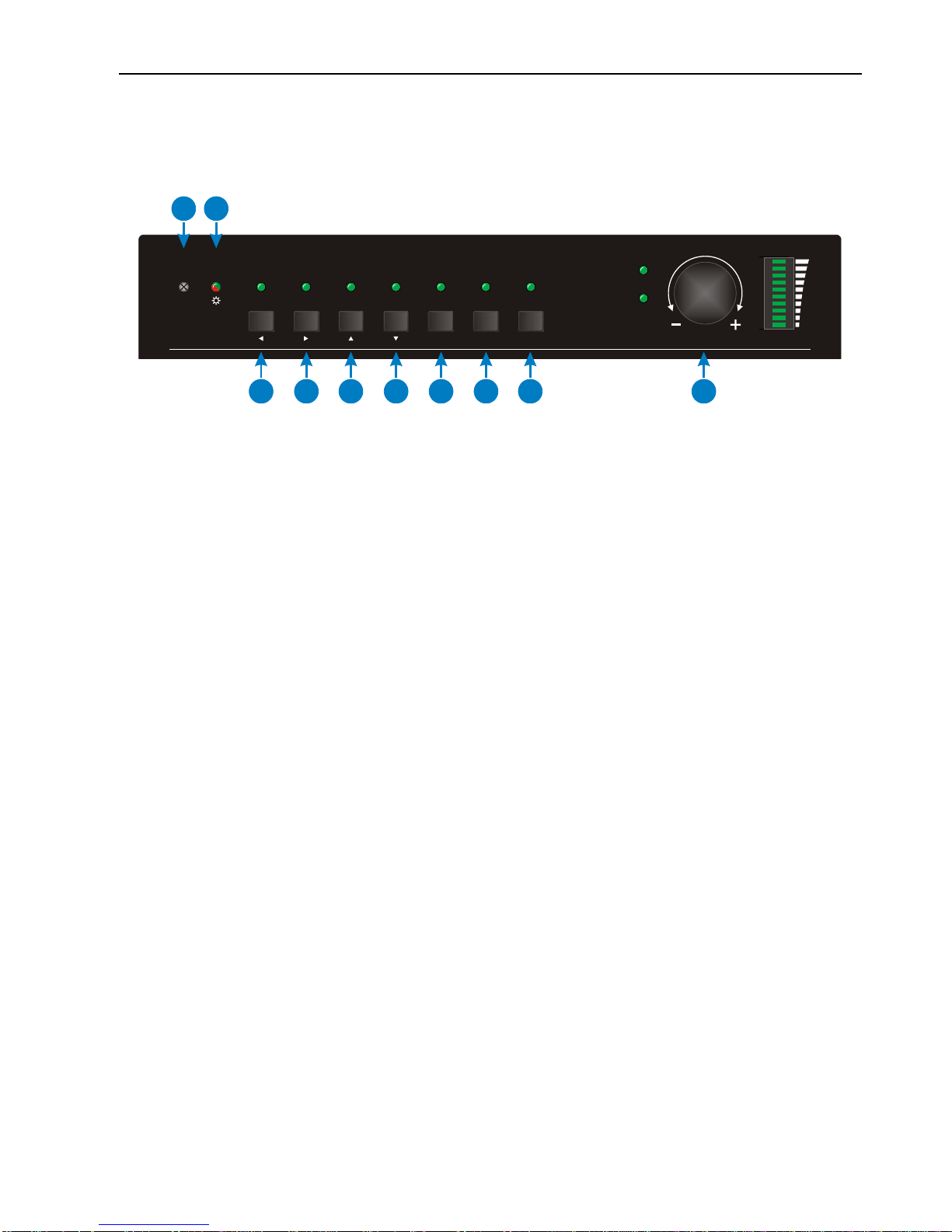
2.1 Seamless Scaler Switcher
Front Panel
①Built-in IR Receiver.
②Power Indicator- RED when the device is in standby, GREEN when device is
powered on and no indicator when there is no power to device.
③1-HDMI/MHL input selector and activity LED/ Left key for OSD.
④2-HDMI input selector and activity LED/ Right key for OSD.
⑤3-HDMI input selector and activity LED/ Up key for OSD.
⑥4-HDMI input selector and activity LED/ Down key for OSD.
⑦5-DP input selector and activity LED/ ENTER key for OSD.
⑧6-VGA input selector and activity LED/ OSD menu button.
⑨Auto switching selector and activity LED.
Press this to enter or exit auto-switching mode.
Long-press this button 3 seconds or more to reset output resolution to 720p or to
activate HDMI and HDBT outputs if they have been turned off.
Note: When you set any VGA port to C-video or YPbPr in Manual-switching mode,
the system will not be able to enter Auto-switching mode.
⑩Volume knob for variable audio control- Push knob in to toggle between ‘MIX’ and
‘Source’ control.
VOLUME
IR
SOURCE
MIX
1-HDMI/MHL 6-VGA
5-DP3-HDMI 4-HDMI2-HDMI AUTO
RES RESET/3sMENU/3sENTER
12
345678910
6-input Seamless Scaler Switcher & HDBaseT Receiver
4
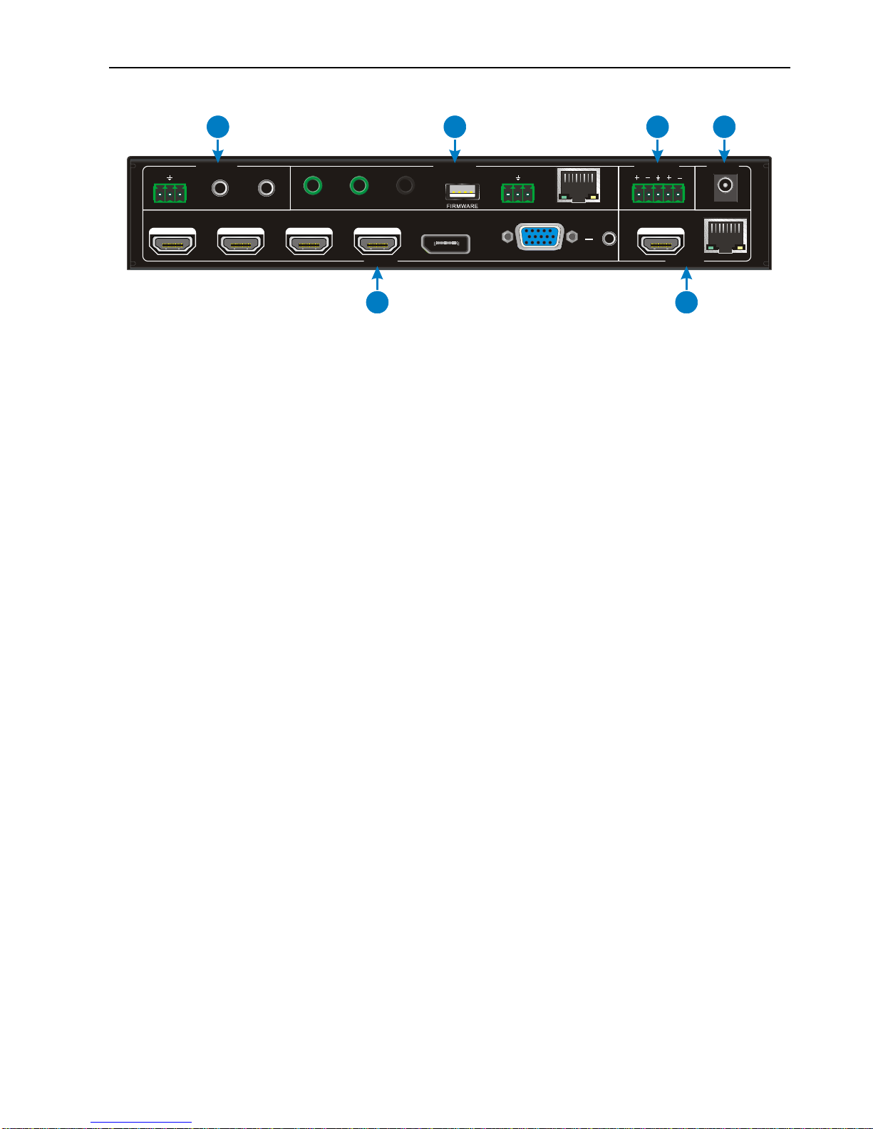
Rear Panel
①INPUTS
- Video input ports: 1 HDMI/MHL, 3 HDMI inputs, 1 DP and 1 VGA.
- Audio input ports: 1 VGA auxiliary audio input.
②OUTPUTS
- HDMI output: HDMI video output port.
- HDBaseT output: Support PoH. Connect with a compatible HDBaseT Receiver to
transmit AV signal, IR or RS232 control signal.
③AUDIO IN
- MIX: 3-Pin phoenix connector for line audio input.
- 1-AUDIO& 2-AUDIO: 3.5mm mini jacks for line audio input.
④CONTROL
IR IN & IR OUT: Connect with IR Receiver and Emitter to control devices via IR.
IR EYE: Connect with the IR Receiver (with carrier wave only) to control this
Scaler Switcher via the including IR Remote.
FIRMWARE: Type-A USB port for updating system firmware or loading
customized EDID data.
RS232: Serial port, 3-pin phoenix connector, connect with a control device (such
as PC) to control the Scaler Switcher or other devices connected with HDBaseT
Receiver.
TCP/IP: Ethernet port, connect with PC to control the Scaler Switcher via GUI.
⑤AUDIO OUT - Stereo balanced L/R audio output.
⑥DC 24V - Locking power port, connect 24V DC power adapter.
Tx Rx
DC 24V
HDBT
L R
HDMI1-HDMI/MHL
IR EYEIR IN IR OUT TCP/IPRS232
AUDIO IN
1-AUDIO 2-AUDIO
L R
MIX
6-VGA2-HDMI 3-HDMI 4-HDMI 5-DP
CONTROL AUDIO OUT POWER
INPUTS OUTPUTS
12
3456
6-input Seamless Scaler Switcher & HDBaseT Receiver
5
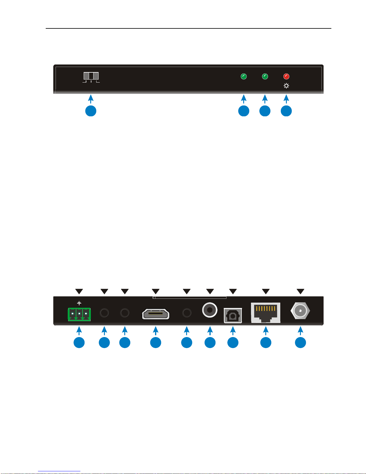
2.2 HDBaseT Receiver
Front Panel
①RS232 Mode switcher
CTRL: RS232 pass-through control mode;
UPDATE A: Update Valens IC program, connect a PC to the RS232 port, and
then double-click the update file (.bat).
UPDATE B: Update the IC program which is used for de-embedding audio, the
upgrade method is the same as the above UPDATE A.
②Link status LED - OFF: No Link / GREEN: Link successful.
③HDCP compliant LED - OFF: No HDMI traffic/GREEN: Traffic with HDCP/Blinking
GREEN: Traffic without HDCP.
④Power LED - RED when device is powered on and no indicator when there is no
power to device.
Rear Panel
①RS232 connector- If one is connected with control device (e.g. PC), and the other
should be connected with the third-party that need to be controlled.
②IR IN - Work with far-end IR OUT port, connect with IR Receiver (with carrier) to
collect IR signal to control far-end display device from local.
③IR OUT - Work with far-end IR IN port, connect with IR Emitter to send IR signal to
control input source device.
④HDMI OUT - HDMI typeAconnector, connect to display.
HDCPLINK
UPDATE A CTRL UPDATE B
1234
Tx Rx
RS232 DC 12VIR OUT HDMI OUT HDBT IN
AUDIO
OUT OPTICAL
OUT
IR IN COAX
OUT
123456789

6-input Seamless Scaler Switcher & HDBaseT Receiver
6
⑤AUDIO OUT -3.5mm stereo audio jack, connect to analog stereo audio device.
⑥COAX OUT - Coaxial audio connector, connect to digital audio device.
⑦OPTICAL OUT - Optical audio connector, connect to optical audio devices.
⑧HDBT IN - Connect to the HDBT OUT socket on HDBaseT Transmitter or Matrix
Switcher via CAT5e/6a/7 cable, support unidirectional PoH technology.
⑨DC 12V power port - Connect to 12VDC power adaptor, or it can be powered via the Scaler
Switcher by PoH technology.
6-input Seamless Scaler Switcher & HDBaseT Receiver
7
3. System Connection
3.1 Usage Precautions
System should be installed in a clean environment and has a prop temperature
and humidity.
All of the power switches, plugs, sockets and power cords should be insulated and
safe.
All devices should be connected before power on.
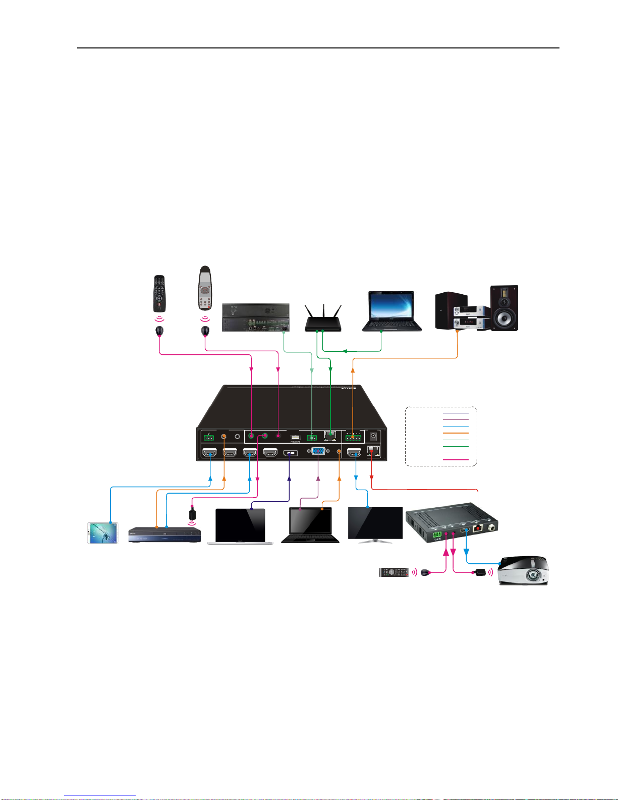
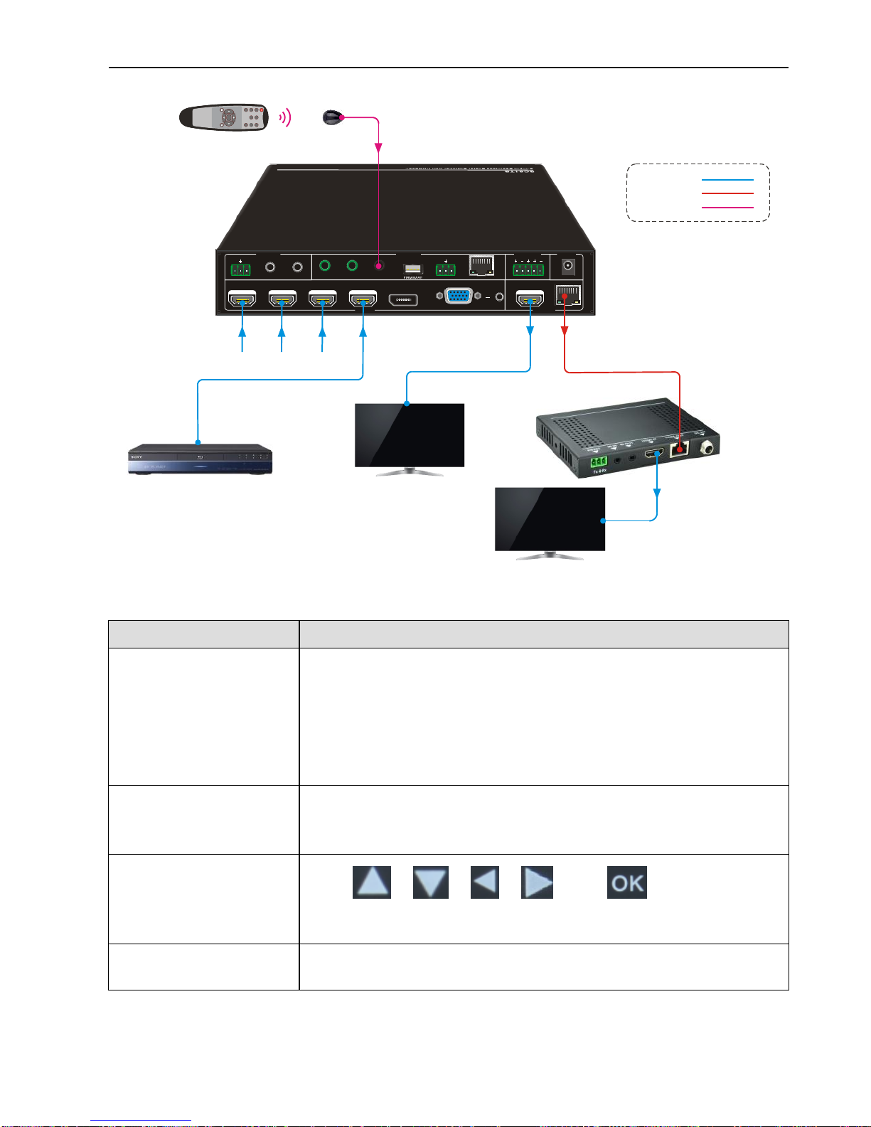
3.2 System Diagram
3.3 Connection Procedure
Step1.Connect HDMI source devices (e.g. Blue-ray DVD) to 1~4 HDMI input ports with
HDMI cables.
Step2.Connect a DP source device (e.g. MacBook) to DP input port with DP cable.
Step3.Connect a VGAsource device (e.g. Laptop) to VGA input port with VGA cable
and VGA audio input port with audio cable.
Laptop TVDVD
Pad MacBook
Tx Rx
DC 24 V
HDBT
L R
HDMI1-HD MI/MHL
IR EY EIR IN IR OU T TCP /IPRS2 32
AUD IO IN
1-AUDIO 2-AUDIO
L R
MIX
6-VGA2-HD MI 3-HDMI 4-HDMI 5-DP
CON TROL AUD IO OUT POWER
INPUTS OUTPUTS
IR Emitter
Projector Remote
Speaker
Scaler Switcher Remote
Control System Laptop
HDBaseT Receiver
DVD Remote IR Receiver
Projector
IR Emitter
IR Receiver Router
HDMI:
VGA:
DP:
Audio:
Ethernet:
HDBaseT:
IR Control:
RS232:
OK
INPUT1
INPUT5
INPUT2 I NPUT 3
INPUT4
Scaler Sw itche r
AUTO
MUTE
VOL

6-input Seamless Scaler Switcher & HDBaseT Receiver
8
Step4.Connect audio source device to the audio input port with audio cable.
Step5.Connect a HDMI display device to HDMI output port with HDMI cable.
Step6.Connect HDBaseT Receiver to HDBT output port with twisted pair.
Step7.Connect speaker, headphone or AV amplifier to AUDIO OUTPUT port.
Step8. Connect control device (e.g. PC) to the TCP/IP port, the Scaler Switcher can
be controlled via web-based GUI.
Step9. Connect control device (e.g. PC, control system) to the RS232 port of the
Scaler Switcher or HDBaseT Receiver (bi-directional RS232 control, either end is
available).
Step10. Connect IR Receiver to the IR EYE port, the Scaler Switcher can be
controlled via IR Remote. For more details, please refer to 5. IR Control.
Step11. Both the Scaler Switcher and HDBaseT Receiver have IR IN and OUT. When
one model is connected with IR Receiver, the other model should connect with an
IR Emitter.
For example: When “IR IN” of the Scaler Switcher connects with an IR Receiver,
the IR Emitter must connect to IR OUT of HDBaseT Receiver.
The IR signal can be transmitted bi-directionally between the Scaler
Switcher and HDBaseT Receiver.
Step12. Connect DC24V power adaptor to the power port (HDBaseT Receiver can be
powered by the Scaler Switcher with PoH function).
Note: If the power adapter is connecting with HDBaseT Receiver, the Scaler Switcher
can’t be powered from HDBaseT Receiver.

6-input Seamless Scaler Switcher & HDBaseT Receiver
9
4. Button Control
Front panel buttons can be used for switching operations and volume adjusting.
4.1 Manual-Switching
Press 1-HDMI/MHL, 2-HDMI, 3-HDMI, 4-HDMI, 5-DP, 6-VGA on front panel to select the
corresponding input source.
4.2 Auto-Switching
Press AUTO to enter in auto-switching mode, and the auto-switching mode abides by
the following principles:
New input
Once detecting a new input signal, the switcher would switch to this new signal
automatically.
Rebooting device
The Scaler Switcher have the ability to save the last configuration before losing
power. If the last switching mode is auto-switching, once rebooted, the switcher will
automatically enter auto-switching mode, then detect all inputs and memorize their
connection status for future rebooting using. If the last displayed signal is still
available, the unit will output the signal. If not, the unit will detect all the input signals
wit priority from 1-HDMI/MHL to 6-VGA. When detected the first signal, it will transfer
to output.
Signal removing
Once removing the current display signal, the Scaler Switcher will detect all input
signals with priority from 1-HDMI/MHL to 6-VGA. It will transfer the signal firstly
detected to be available to output devices.
Note: Auto-switching function works only when inputting new signal, removing a signal
or power rebooting. With any VGA port set to C-video or YPbPr, the system will be not
able to enter in Auto-switching mode.
4.3 Volume Adjusting
Press Volume knob to select MIX or Source audio to adjust, the corresponding LED will
turn green and keep on, and then move the volume knob in clockwise or anti-clockwise
direction to turn up/down sound volume.
6-input Seamless Scaler Switcher & HDBaseT Receiver
10
5. IR Control
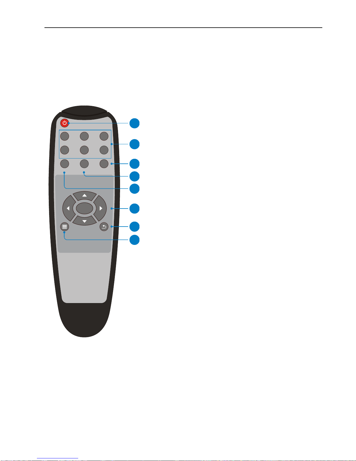
5.1 IR Remote
Connect IR receiver to IR EYE port, the Scaler Switcher cans be controlled by using the
including IR Remote. As CEC function, it is able to use the IR Remote to turn on/off the
HDMI source or Display.
①Enter/ exit standby mode.
②Input channel selection buttons (1~6): Select
video source via pressing corresponding button
(audio switched following the corresponding video
signal).
③Mute/ unmute audio
④VOL: Volume adjusting button. After pressing
this button, the volume adjusting menu will be
showed on Display, and then press UP/DOWON
button to turn up/down volume.
⑤Auto button: Enter/Exit auto-switching mode.
⑥OK: confirm button; Navigation buttons:
UP/DWON/LEFT/ RIGHT button, for value setting
or page-turn.
⑦Exit button: Exit OSD menu or current
operation.
⑧Enter OSD menu or return to previous menu.
OK
1-HDMI
5-DP
2-HDMI 3-HDMI
4-HDMI
Scaler Switcher
6-VGA
MUTE
AUTO VOL
1
2
3
6
7
4
5
8
6-input Seamless Scaler Switcher & HDBaseT Receiver
11
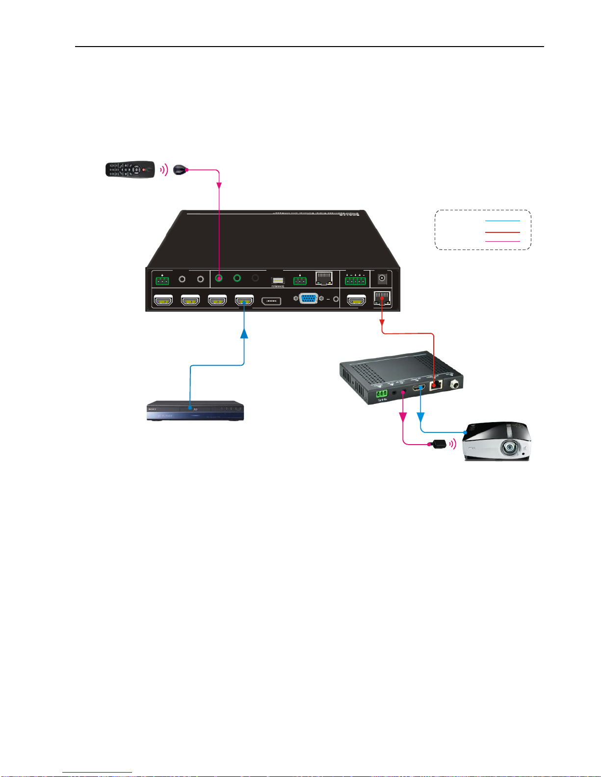
5.2 Control Far-end Display Device
Connect an IR Receiver to IR IN port on the Scaler Switcher and connect IR Emitter to
the IR OUT port on the HDBaseT Receiver, the far-end device(such as Projector) can be
control by its IR Remote.
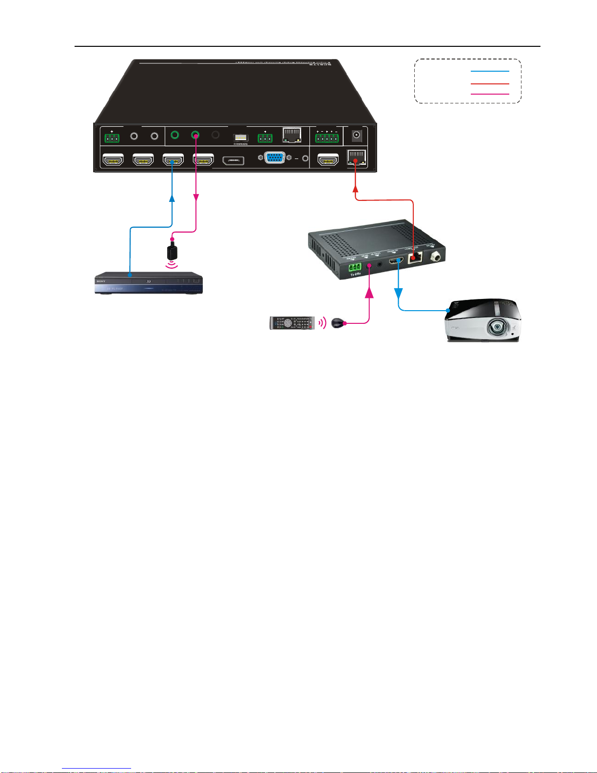
5.3 Control Local Source Device
Connect an IR Emitter to IR OUT port on the Scaler Switcher and connect IR Receiver
to the IR IN port on the HDBaseT Receiver, the source device (such as DVD) can be
control by its IR Remote.
Tx Rx
DC 24V
HDBT
L R
HDMI1-HDMI/MHL
IR EYEIR IN IR OUT TCP/IPRS232
AUDIO IN
1-AUDIO 2-AUDIO
L R
MIX
6-VGA2-HDMI 3-HDMI 4-HDMI 5-DP
CONTROL AUDIO OUT POWER
INPUTS OUTPUTS
Projector Remote
DVD
HDBaseT Receiver
Projector
IR Emitter
IR Receiver
HDBaseT:
IR Control:
HDMI:
6-input Seamless Scaler Switcher & HDBaseT Receiver
12
5.4 CEC Function
The Scaler Switcher supports CEC, it can be turned on/ off by sending RS232
commands or OSD menu operations. The default setting is ON.
Commands pertaining to CEC: “50686%”(enable CEC) and “50687%”(disable CEC)
HDMI INPUT ports support CEC, if the connected source devices also support CEC and
their CEC are on, users can control the source device and display via the IR Remote of
the Scaler Switcher.
Tx Rx
DC 24V
HDBT
L R
HDMI1-HDMI/MHL
IR EYEIR IN IR OUT TCP/IPRS232
AUDIO IN
1-AUDIO 2-AUDIO
L R
MIX
6-VGA2-HDMI 3-HDMI 4-HDMI 5-DP
CONTROL AUDIO OUT POWER
INPUTS OUTPUTS
IR Emitter
DVD
HDBaseT Receiver
Projector
DVD Remote IR Receiver
HDBaseT:
IR Control:
HDMI:
6-input Seamless Scaler Switcher & HDBaseT Receiver
13
The working status related to CEC and STANDBY is showed as below:
Situation
Working Status
CEC: on, Standby: on
Press STANDBY button on IR Remote, the Scaler Switcher
enters in standby mode, so do all HDMI source devices and
display.
Press STANDBY button again on IR Remote, the Scaler
Switcher exits standby mode, the previous selected HDMI
input source device and display start working too.
CEC: on, Standby: off
Press STANDBY button on IR Remote, the Scaler Switcher
enters in standby mode, HDMI source devices and display
keep on.
CEC: on
Use , , , and buttons on IR
Remote to control HDMI source device.
CEC: off
Unable to control HDMI source device and display through IR
Remote
Tx Rx
DC 24V
HDBT
L R
HDMI1-HDMI/MHL
IR EYEIR IN IR OUT TCP/IPRS232
AUDIO IN
1-AUDIO 2-AUDIO
L R
MIX
6-VGA2-HDMI 3-HDMI 4-HDMI 5-DP
CONTROL AUDIO OUT POWER
INPUTS OUTPUTS
TV
TV
Scaler Switcher Remote
HDBaseT Receiver
IR Receiver
DVD
HDMI:
HDBaseT:
IR Control:
OK
INPUT 1
INPUT 5
INPUT 2 INPUT 3
INPUT 4
Scale r Switc her
AUTO
MUTE
VOL

6-input Seamless Scaler Switcher & HDBaseT Receiver
14
6. RS232 Control
As RS232 can be transmitted bi-directionally between the Scaler Switcher and
HDBaseT Receiver, so it is able to control a third-party device from local or control the
Scaler Switcher from remote. The baud rate support 2400, 4800, 9600(default), 19200,
38400, 57600 or 115200.
6.1 RS232 Connection
There are two RS232 control modes can be chosen via RS232 commands
(50787%/50788%).
①Control Scaler Switcher or Third-party Device from Local
Firstly, according the following connection diagram to connect all devices as needed.
Secondly, send command 50787% (serial control mode 1, factory default) via RS232
communication software.
Lastly, send the right command of the Scaler Switcher or other remote RS232 device
connected in present system.
Tx Rx
DC 24V
HDBT
L R
HDMI1-HDMI/MHL
IR EYEIR IN IR OUT TCP/IPRS232
AUDIO IN
1-AUDIO 2-AUDIO
L R
MIX
6-VGA
2-HDMI 3-HDMI 4-HDMI 5-DP
CONTROL AUDIO OUT POWER
INPUTS OUTPUTS
Third-party device
Laptop
HDBaseT Receiver
HDBaseT:
RS232:

6-input Seamless Scaler Switcher & HDBaseT Receiver
15
②Control Scaler Switcher or Third-party Device form Remote
Firstly, according the following connection diagram to connect all devices as needed.
Secondly, send command 50788% via RS232 communication software.
Lastly, send the right command to control the Scaler Switcher:
6.2 Installation/uninstallation of RS232 Control Software
Installation Copy the control software file to the computer connected with the
Scaler Switcher.
Uninstallation Delete all the control software files in corresponding file path.
Basic Settings:
First to connect the Scaler Switcher with all input devices and output devices needed,
then to connect it with a computer which is installed with RS232 control software.
Double-click the software icon to run this software.
Here we take the software CommWatch.exe as example. The icon is showed as below:
Tx Rx
DC 24V
HDBT
L R
HDMI1-HDMI/MHL
IR EYEIR IN IR OUT TCP/IPRS232
AUDIO IN
1-AUDIO 2-AUDIO
L R
MIX
6-VGA
2-HDMI 3-HDMI 4-HDMI 5-DP
CONTROL AUDIO OUT POWER
INPUTS OUTPUTS
Third-party device
Laptop
HDBaseT Receiver
HDBaseT:
RS232:
Table of contents
Other Vivo Link Switch manuals

Vivo Link
Vivo Link VL120000 User manual

Vivo Link
Vivo Link VL120002 User manual

Vivo Link
Vivo Link VL120020 User manual

Vivo Link
Vivo Link VL120014 User manual

Vivo Link
Vivo Link VLSW141H User manual

Vivo Link
Vivo Link VLHUB121-MME User manual

Vivo Link
Vivo Link VLSC262 User manual

Vivo Link
Vivo Link VLSC151H User manual


