manuals.online logo
Brands
  1. Home
  2. •
  3. Brands
  4. •
  5. Atdec
  6. •
  7. TV Mount
  8. •
  9. Atdec TH-VWP-050 User manual

Atdec TH-VWP-050 User manual

TH-VW Series Page 1 of 6
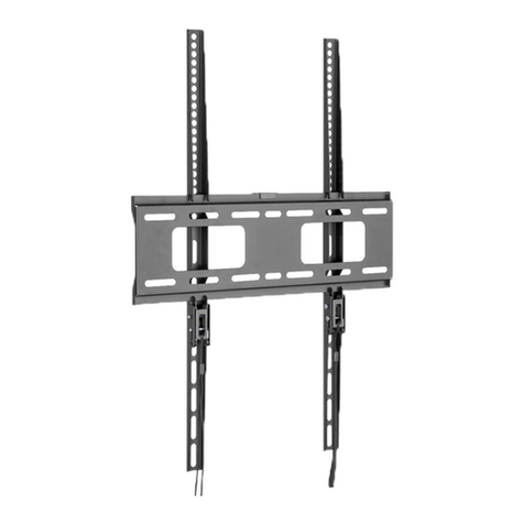
COMPONENT CHECKLIST
E
TH-VWV
Bracket (x2)
F
TH-VWVP
Bracket (x2)
A
TH-VWP-050
Wall Plate 50cm (19-5/8”)
B
TH-VWP-080
Wall Plate 80cm (31-1/2”)
C
TH-VWP-100
Wall Plate 100cm (39-3/8”)
D
TH-VWP-160
Wall Plate 160cm (63”)
G
Phillip Head Screw
M6 x
16/30/45/60mm
(x4)
Bracket Hardware
(Supplied with TH-VWV and TH-VWVP)
H
M6 Washer
(x4)
J
Spacer
(x8)
I
Security Screw
M8 x
16/30/50/65mm
(x4)
8mm Coach Screw/
DynaBolt /ChemSet Nylon Anchor M8 Washer
TM TM
Installation Guide
TH-VWP-050
TH-VWP-080
TH-VWP-100
TH-VWP-160
TH-VWV
TH-VWVP
TH Universal Video Wall Mount
REQUIRED
TOOLS
WEIGHT
RANGE
Per Wall Plate*
0 - 165kg
(0 - 363lb)
Per Bracket Pair
0 - 165kg
(0 - 363lb)
Illustrated Solution is a video wall assembled using TH-VW components.
The TH Universal Video Wall Mount is a modular system. Components can be configured
to accommodate different sizes, quantities, and orientations of displays.
Note:
! Wall Plate mounting fasteners are NOT
supplied with Wall Plates
! Professional installer to ensure correct
mounting fastener type, location & quantity
to suit structure where Video Wall is
installed
! Wall plate to be fixed to wall with a
minimum of 3x appropriate load bearing
fasteners per Wall Plate and minimum of
2x appropriate load bearing fasteners per
Display
! Washers must be used when securing Wall
Plate/s
! Example of Wall Plate mounting fasteners:
*Wall Plate only achieves
maximum weight rating
when appropriately fastened
to a wall of adequate
structural capacity
• Power Drill
• Suitable Drill Bit
• Fasteners for Wall
Plate attachment
• Driver for chosen
Wall Plate fasteners
• Phillips Head
Screwdriver
• Spirit Level
• Tape Measure
• Stud finder
TH-VW Series Page 2 of 6
IMPORTANT INFORMATION
! Please ensure this product is installed as per these installation instructions.
! The manufacturer accepts no responsibility for incorrect installation.
! Failure to mount this product correctly may cause serious injury/death during or following installation.
! This product should only be installed by professional installers of good mechanical aptitude, who have experience with basic building
construction, and fully understand these instructions and the consequences of incorrect installation.
! Two person installation is recommended.
! Use mechanical lifting equipment for safe lifting and positioning of equipment where appropriate to ensure careful installation - AV
equipment is fragile and can be heavy.
! Some walls are not suitable for Video Wall installation - check load capacity of wall prior to installation. Failure to provide adequate
structural strength for this product can result in serious injury to persons or damage to equipment. It is the professional
installer’s responsibility to ensure suitable structural capacity of wall (including appropriate safety factor) to support total weight of
all equipment being mounted. Reinforce the wall structure and consult a structural engineer where required.
! Drilling into electrical wires can cause death - use appropriate equipment and caution when drilling holes in walls to avoid electrical
cables, water pipes and gas pipes. Do not drill into structures unless you have established it’s safe to do so.
! Ensure that the Video Wall is installed out of reach of public.
! Product not suitable for use outdoors.
! Do not use this product for mobile applications.
! After installation is complete check to verify that Video Wall is secure and safe for use.
1. Mount Brackets to screen
OPTION A If the distance between the
top of the display & mounting bracket
is 80mm or less, mount directly onto
the screen.
OPTION B If the distance between the
top of the display & mounting bracket
is between 80 and 165mm, mount
using spacers included.
NOTE
To function correctly, top of the Bracket must
be mounted as close to the top of the screen as
possible - but Bracket must not be higher than the
top of the screen.
These considerations are to allow angle necessary to
install displays.
When mounting multiple screens the Brackets must
be mounted in exactly the same position each time
to ensure alignment.
0~80mm
80~165mm
SPACER
0~80mm
80~165mm
SPACER
2. Mount first Wall Plate
2.2 Measure the height
between the top of the
hook to the bottom of
the screen.
X X
Y
Y
2.1 Determine the
desired height of your
screen from the floor.
TH-VW Series Page 3 of 6
X
Y
Contact edge
with the hook
Z X Y
= +
2.3
8 x 17
MAX 225 (7”)
MAX 600 (24”)
8 x 17
8 x 17
STEP A Combine both heights
to find the height of the contact
edge of the Wall Plate & mark
this on the wall.
STEP B Position your Wall Plate,
aligning the contact edge to your
mark.
STEP C Consider lateral location
based on display positions, length
and quantity of Wall Plates.
NOTE
Wall Plate mounting fasteners into load bearing structure to be a MAXIMUM of 600mm (24”) apart
Wall Plate mounting fasteners into load bearing structure to be a MAXIMUM of 225mm (7”) from
end of Wall Plate
Wall Plate to be fixed to wall with a minimum of 3x appropriate load bearing fasteners per Wall Plate
and minimum of 2x appropriate load bearing fasteners per Display
Attach Wall Plate mounting fasteners evenly and regularly along length/s of Wall Plate/s.
2.4 Use the Wall Plate as a template
to mark mounting fastener locations.
IMPORTANT INFORMATION
! Drilling into electrical wires can cause death - use appropriate equipment and caution when drilling holes in walls to avoid electrical
cables, water pipes and gas pipes. Do not drill into structures unless you have established it’s safe to do so.
! Choice and supply of appropriate Wall Plate mounting fasteners is the responsibility of the installer. Consult a structural engineer
where required.
! Wall Plate mounting fasteners are to be used as per manufacturers’ instructions, including hole diameter and minimum engagement
to achieve necessary performance.
! On Stud Wall/Drywall use a good quality Stud Finder to position mounting fasteners in the centre of studs.
! On Masonry wall avoid positioning Wall Plate mounting fasteners in a mortar join.
Please use a Spirit Level during installation to
ensure that the Wall Plate is LEVEL
TH-VW Series Page 4 of 6
3.1 Refer to Step 2.4 to install
adjoining Wall Plates.
Please use a Spirit Level during installation to
ensure that the Wall Plates are LEVEL
3. Mount remaining Wall Plates as applicable
Match Profiles
3.2 To find the next row height:
Height between Wall Plates = Overall Height of Screen
TIP: Use Wall Plate as a drilling template.
IMPORTANT! Any structural elements must be capable of supporting the combined weight of all the equipment and devices being mounted. If in doubt,
consult a structural engineer.
Don’t forget to choose and use
appropriate Washers!
TH-VW Series Page 5 of 6
4.1 Install the screens row by row,
starting at the bottom. Ensure each row
of screens is level before moving on to
the next row.
Installation may start from left or right.
4.3 Screen levelling 4.4 Wall levelling
Screen shown in Landscape orientation
Screen shown in Portrait orientation
4. Mount Screens
Please use a Spirit Level during installation to
ensure that the screens are LEVEL
Angle the screen as
shown and position
so the hook is above
the bracket.
Lower the hook
onto the bracket to
engage, and gently
lower the screen.
Phillips
head screw
driver
+/- 5mm
Level the screen by adjusting the
screw at the top of each mounting
bracket. Use a spirit level to ensure
screen is level.
To adjust for uneven
walls, screw the
leveling bolt in or
out to match each
display position.
Levelling
bolt
5. Cabling
Tilt up each row, starting at the top, leaving
each screen out until all cabling is finished.
You may start from the left or right.
5.1 Cabling sequence
Screen shown in Landscape orientation
Screen shown in Portrait orientation
4.2 Hang screen
TH-VW Series Page 6 of 6
No portion of this document or any artwork contained herein should be reproduced in any way without the express written consent of Atdec Pty Ltd.
Due to continuing product development, the manufacturer reserves the right to alter specifications without notice. ©20210129
6. Security (optional)
7. Screen Removal
The holes shown in the bracket and wall plate
can accommodate security cabling and locks.
To remove screen X for repair or replacement,
tilt up the numbered screens in sequence, then
pull out and lift off screen X.
5.2 To gain access for cabling:
Pull out the
bottom of the
screen.
Rotate out the
stop found on
each bracket.
Rotate up the stop
and gently lower
the screen onto
the wall.
12
3
x
1 2
3x2
1
x
Wall Plate
Locks &
cabling not
supplied

This manual suits for next models

5

Other Atdec TV Mount manuals

Atdec AWM-BT User manual

Atdec

Atdec AWM-BT User manual

Atdec AD-WF-5040 User manual

Atdec

Atdec AD-WF-5040 User manual

Atdec telehook TH-2250-VTP User manual

Atdec

Atdec telehook TH-2250-VTP User manual

Atdec AD-TVC User manual

Atdec

Atdec AD-TVC User manual

Atdec AW-ORA-F User manual

Atdec

Atdec AW-ORA-F User manual

Atdec TH-3270-UFM User manual

Atdec

Atdec TH-3270-UFM User manual

Atdec spacedec SD-DP-420 User manual

Atdec

Atdec spacedec SD-DP-420 User manual

Atdec AWM-P40X User manual

Atdec

Atdec AWM-P40X User manual

Atdec AD-WT-5040 User manual

Atdec

Atdec AD-WT-5040 User manual

Atdec AWM-W User manual

Atdec

Atdec AWM-W User manual

Atdec telehook TH-3070-CTL User manual

Atdec

Atdec telehook TH-3070-CTL User manual

Atdec AWM-A13H User manual

Atdec

Atdec AWM-A13H User manual

Atdec TH-VA-2X2-NEC X463 User manual

Atdec

Atdec TH-VA-2X2-NEC X463 User manual

Atdec AV Cart 20 User manual

Atdec

Atdec AV Cart 20 User manual

Atdec telehook TH-2050-VFM User manual

Atdec

Atdec telehook TH-2050-VFM User manual

Atdec 5060 User manual

Atdec

Atdec 5060 User manual

Atdec AD-WF-10090 User manual

Atdec

Atdec AD-WF-10090 User manual

Atdec VF-AT-W User manual

Atdec

Atdec VF-AT-W User manual

Atdec AWM-ADTC User manual

Atdec

Atdec AWM-ADTC User manual

Atdec AWM-BT User manual

Atdec

Atdec AWM-BT User manual

Atdec AWMS-2-D13-F User manual

Atdec

Atdec AWMS-2-D13-F User manual

Atdec VTB-FD User manual

Atdec

Atdec VTB-FD User manual

Atdec 5060 User manual

Atdec

Atdec 5060 User manual

Atdec AD-WM-9080 User manual

Atdec

Atdec AD-WM-9080 User manual

Popular TV Mount manuals by other brands

Blaupunkt 330323 owner's manual

Blaupunkt

Blaupunkt 330323 owner's manual

USX-MOUNT XML006-24K-1 instruction manual

USX-MOUNT

USX-MOUNT XML006-24K-1 instruction manual

Sanus Sanus VisionMount LL11-B1 Brochure & specs

Sanus

Sanus Sanus VisionMount LL11-B1 Brochure & specs

ricoo S0711 quick start guide

ricoo

ricoo S0711 quick start guide

Metra Electronics 99-7367 installation instructions

Metra Electronics

Metra Electronics 99-7367 installation instructions

Tuff A2007 installation manual

Tuff

Tuff A2007 installation manual

Steren CCTV-350 instruction manual

Steren

Steren CCTV-350 instruction manual

Sony KDL-32ML130 - 32" Bravia M-series Digital Lcd... instructions

Sony

Sony KDL-32ML130 - 32" Bravia M-series Digital Lcd... instructions

AVF DEL404-D manual

AVF

AVF DEL404-D manual

Premier Mounts TWM-103 Specifications

Premier Mounts

Premier Mounts TWM-103 Specifications

SANUS VuePoint F80b instruction manual

SANUS VuePoint

SANUS VuePoint F80b instruction manual

Hama NEXT 00084446 manual

Hama

Hama NEXT 00084446 manual

Connects2 CAM-20 user manual

Connects2

Connects2 CAM-20 user manual

SANUS VuePoint F215B instruction manual

SANUS VuePoint

SANUS VuePoint F215B instruction manual

peerless-AV ACC-DSV503 Installation and assembly

peerless-AV

peerless-AV ACC-DSV503 Installation and assembly

Innovitech X Filter Extension Brackets quick start guide

Innovitech

Innovitech X Filter Extension Brackets quick start guide

delight 39688 quick start guide

delight

delight 39688 quick start guide

QSC HPR122i user manual

QSC

QSC HPR122i user manual

manuals.online logo
manuals.online logoBrands
  • About & Mission
  • Contact us
  • Privacy Policy
  • Terms and Conditions

Copyright 2025 Manuals.Online. All Rights Reserved.