viZaar INVIZ BIG User manual


www.vizaar.com
The device identification “INVIZ” stands
for a series of latest inspection cameras,
which are constructed strictly according
to the instructions of the users.
The video endoscope at hand,
”INVIZ BIG”, is currently the simplest and
at the same time most hard wearing
camera technology for the inspection and
documentation of weld seams and pipe
inner walls in the 30 mm – 300 mm
category. Expect high resolution, impres-
sive colours, highest light sensitivity, full
image, digital image and video memory
as well as a smart text generator option.
irst models of the INVIZ BIG series and
previous are in the market since about 10
years and have been proved to be one of
the most ‘ruggedized’ inspection cameras
in the world. The percentage rate of
failure during the first two years of
operation is less than 5% - not reached
through any other RVI video - equipment
in today’s market place.
By continually and consistently not
including the electrical conductors of the
KEVLAR – reinforced main cable inside
one epoxy-glass fibre pushing pole, the
system keeps difficult flexibillity of tur-
ning multiple corners and bends without
breaking the main camera supply.
The immense amount of options and
custom made accessories will allow the
operator to reach any point of the
application:
:: Simple rotating and maneuvering of the
probe with attached NEW side view optics.
:: Waterproofness up to 50 meter.
:: Longterm-tested durability of the entire
probe through high wall thickness of
the probe.
:: Extremely light sensitive 40mm camera
head, interchangeable with 29mm
standard head.
:: Manoeuverability through many pipe
bends. A widest range of pushing- and
centering tools are supporting the
operator to accomplish his task.
:: Easy focusing of the optics within a
wide range of applications.
:: New several hours lasting
battery-operation option.
In order to obtain the economic advantages
of your endoscope even in the long run,
you ought to read and follow the following
advice, tips and warnings carefully. The
observance of these instructions serve
the purpose of your own safety as well as
the safety of those in the work field of the
endoscope as well as that of the
corresponding control device.
All tips, code of behaviour, suggestions
for measures to be undertaken, advice,
warnings and instructions are exclusively
valid for the operation of “INVIZ” BIG
videoscopes and not for devices by other
manufacturers.
or questions, which have not been
answered by this instruction manual,
your dealer and/or the manufacturer are
gladly available for advice. Kindly contact
us even if you have suggestions for the
improvement of this manual or the product.
We wish you success during your inspections!
Preface
:: Status / Revision: 10 / 2007

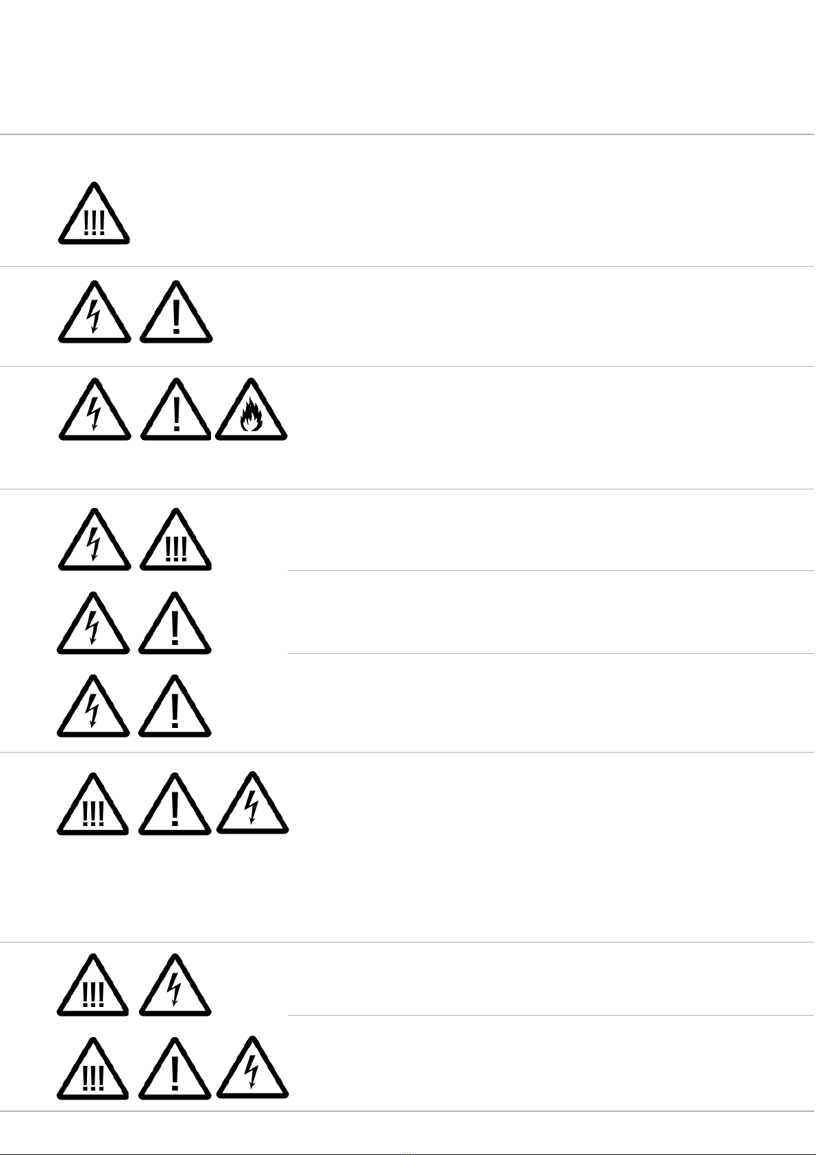
Warning against risk of injury or
loss of life to humans
Warning against significant risk of
damage to device and plant
Warning against fatal electric shock
Warning against life-threatening
explosion risk
Warning against life-threatening fire risk
Before the initial operation, this instructions
manual must be completely read and
understood by the user in order to
exclude damage to life and property
through the operation of the video
camera system (the device) with the
greatest degree of safety. The operation
of the device without the understanding
of the instructions manual is not allowed
under any circumstances. The device has
been conceived exclusively for industrial
application exclusively through personnel
trained in all technical questions and
must never be operated by private users.
or a generally non-destructive operation
of the device, beside the safety of the
personnel and environment, an extensive
knowledge of the device, the inspection
technology, the safety instructions as well
as the industrial field of application are
absolutely necessary!
or compulsory attention:
Compulsory instructions
for a safe start-up in
accordance with regulations.
Reading before the initial
operation is an absolute must!
The device must never be connected to
electric mains, if you have not understood
this instruction including safety warnings
or even if you have not understood
individual sections or if you cannot or do
not wish to use the device in accordance
with the regulations.
viZaar is not liable under any circumstances
for the consequences of faulty inspection
results, which were achieved with the device.
viZaar shall not be liable under any
circumstances for the loss of inspection
data.
viZaar shall not be liable under any
circumstances if device parts are left
behind in the inspected plant inadvertently.
Operating precautions
www.vizaar.com
The device or parts thereof must never be
inserted into human body openings
and / or used for (veterinary) medical
analyses.
The device must never be opened by the user
at any place other than the camera housing.
Life-threatening electric voltage are used or
generated in the device; in particular, the
device must never be used with the
The video probe of the device must never
be used in or in the vicinity of apparatus
or equipment, which are partly or fully
energized by electric current of any type
(e.g. transformers, motors, generators,
switchboards etc.). The metallic housing of
In case an exchange of the lamp becomes
necessary, one must proceed according
to the procedure in the instructions!
The device must never be operated in
moist environment (e.g. during
precipitation) nor must the control device
Before start-up, the device must be
acclimatized according to the ambient
temperature. This is valid in particular for
cooled devices, wherein condensate
The device must never be operated with
damaged video probe. There is a risk of
damage to hand due to the metallic
protective mesh (Suggestion: Always
wear work gloves for protection). At the
same time, there is a danger that liquids
might penetrate the probe and thereby
impair the functioning permanently or
might cause a life-threatening electric
shock to the operator! Even the use of a
Never operate the probe without working
gloves! Considerable risk of getting
adjusted!
Never operate the device under conditions
which do not comply with the operating
conditions or storage conditions described
in the instructions manual!
housing open. The device must never be
used when there are audibly loose parts
inside the device.
the camera conducts electricity and dange-
rous currents are transmitted during every
contact or even short-circuits can be trig-
gered in the plant.
or the operating pendant be submerged
in water – there is a risk to life due to
electric currents!
accumulation during warm-up can lead to
destruction and damage due to electric
sparkover.
slightly damaged probe can quickly lead
to the total destruction of the probe due
to the electric conductors lying inside.
The operation of a damaged probe is
impermissible within the area of jurisdic-
tion of the European Union, since the
regulations on emission of electro-
magnetic radiation can no longer be
adhered to with safety.
At the same time, protective glasses must
always be worn while operating the probe.
www.vizaar.com

The device must never be operated in
operating environments which are vulne-
rable to explosion or fire risk. The device
is not equipped with safety devices or
acceptance for operation in environments
vulnerable to explosion or fire risk. An
impermissible employment in
The device must be checked annually by
the manufacturer or an authorized third
party for compliance with the electrical
safety instructions obligatory at the usage
site and conformance with the as-delivered
condition of the device. The device must
not be connected to the electric supply
Never allow the device to be operated
without supervision. or safety reasons,
it is necessary to switch-off the machine
during pauses.
Never operate the device in radio-actively
contaminated environment! Never expose
the probe to ionizing radiation of any type!
Never bring the probe in contact with
corrosive substances of any kind (acid or
alkali). Risk of damage and injury while
manipulating the probe.
Never insert the probe in plant parts the
contents of which are unknown!
or increasing your own safety against
electric shocks with risk of injury or loss
of life, the device must always be connec-
ted and operated via a residual current
circuit breaker system or an isolating
transformer.
This can in any case be a compulsory
The device must be transported exclusive-
ly in the transport case conceived for it by
the manufacturer. The device and the
corresponding accessories must be
environments susceptible to explosion or
fire leads unavoidably to a device-induced
life-threatening explosion and to a fire in
the plant. The operator is obliged
to check the plant for substances vulne-
rable to explosion or fire before every
new start-up of the device.
mains or otherwise operated after the
ascertainment of a defect or any deviation
from the as-delivered condition. This is
valid, in particular, if the device has tumbled
or fallen down or was exposed to a liquid.
Never bring the probe in contact with
solvent containing liquids! Risk of
Damage!
condition depending upon the operating
environment. or this, consult your
responsible safety in-charge or the
accident protection measures in force in
your respective country.
packed in the transport case only
according to the instructions at hand.
www.vizaar.com

The use of too long power extension
cords is life-threatening and forbidden
(max. 25 m in case of a supply line made
of copper 3 x 1.5 mm2). Hereby, a
life-threatening loss of the protective
function of the upstream safety element
is possible. At the same time, voltage
differences of the earth potential as
Always ensure that the respectively
inspected metallic pipeline systems
conform exclusively to a homogenous
earthing potential; electrically insulated
transition points (e.g. sealings, plastic
line sections) can exhibit different electric
earth voltage potentials depending upon
The endoscope system can be connected
to the public electric supply mains through
a ‘IEC-plug lead’ included in the delivery
or a ‘IEC-plug lead’ which complies with
the local socket standards. The system
accepts faultlessly all power supplies
known worldwide with alternate currents
of 96 VAC to 246 VAC at 46 to 60 Hz.
Never insert the probe in plant parts, if
weld or cutting work is being undertaken
simultaneously or soon. Likewise, the
probe must never be inserted if further
inspection procedures like eddy current
or radiography tests are being undertaken
Exclusively the viZaar accessory articles
or spare parts described in this instructions
manual may be used in connection with
the device.
Never look directly at the light emission
in the camera head. There is danger of
lasting eye injury or at least a long-lasting
eye irritation with accidental consequen-
ces through a temporarily restricted
power of vision.
When operating the device outside the
permissible operating conditions or with
destruction caused by usage which deviates
from the instructions, non-compliance with
the operating conditions or through the
usage
The different options / accessoires
require handling which is different each
time and deviate from each other signifi-
cantly even in the technical specifications.
compared to the displaced reference
point of electric output (bridged by a too
long extension cord) could cause dange-
rous electric currents on contact with the
device housing or impermissibly high
equalizing currents at the probe. In case
of uncertainties, consult your on-site
electrical expert.
the plant, which could build up very high
electric currents with sparking and
substance burn-out in case of bridging
through the metallic, electrically
conducting probe. Kindly consult your
on-site expert in advance.
or safe operation, the device needs a
reliable potential earth (PE) connection.
In case of doubt, an expert or the
manufacturer must be consulted. The
minimum output supplied by the power
connection can be derived from the devi-
ce specifications contained in the instructi-
ons.
on the same plant part. Never insert the
probe in plant parts, which are not fully
switched-off (e.g. danger from rotating
plant components) or cooled down.
of non-original spare parts or accessories as
well as through impermissible opening of
the device, the guarantee obligation or the
guarantee commitment by the supplier or
manufacturer lapses, in principle.
The enclosed operating and application
instructions of the respective option must be
compulsorily adhered to.
www.vizaar.com

Never insert the probe in pressurized
containers or pipelines via sluices! The
entire probe is watertight up to the length
of the probe in most devices but is not
designed for fluid or general gas
pressure higher up. Beside the danger of
destruction through pressure forces,
Using the optional pushing poles and / or
pushing reel causes additonal endanger-
ment of the operator: Glass-fibre epoxy
poles may have splices on the surface
and can cause heavy injury of your hand
during handling. Always use rugged wor-
king gloves when operating with epoxy –
glass fibre pushing poles
Using the optional pushing poles and / or
pushing reel causes additonal endanger-
ment of the operator and facility: Endless
push poles on a reel are winded under a
enormous spring force – in the case you
open the reel break without keeping the
Using the optional pushing poles and / or
pushing reel causes additonal endanger-
ment of the facility: Defective or false
operated push poles may get stuck inside
the application without a chance of easy
retrieval. Never push the poles too
strongly, always inspect poles before
starting the inspection.
Using the optional pushing poles cause
additonal endangerment of the facility:
Always approve 100% push poles are
connected properly to each other ( exten-
sion) or to the camera before inserting
the probe. Not correctly linked pole-con-
Be careful employing centering tools to
the probe. aulty operated or wrong
chosen centering trollies or rings can
cause the probe getting stuck inside
tubes and affiliated bends behind
obstacles, bends and weldings etc.
there is the danger of uncontrolled exit of
pressure medium into the control device
via a leaky probe. Depending on the pro-
perties of the pressure medium, there is
significant risk of injury or accident.
open end of the push pole under control,
the reel will unwind very fast and can
cause heavy injury to the operator and
persons nearby. Also any neighboring
material can be destroyed through a push
pole moving uncontrolled and fast.
nectors / locks will cause the fatal situa-
tion to open immediately when starting to
retrieve the probe after inspection (during
pulling). This will disable the operator to
retrieve the probe if one or more bends
have been inspected (getting stuck).
www.vizaar.com

1 Structure and start-up
1.1 Removal from the transport case
1.2 Accessories
1.3 Initial operation
1.4 urther functions of the basic system
1.5 ocusing
2 Product specifications
3 Supplementary equipment
3.1 Option push poles and pushing rods
3.2 Option centering tools and trollies
3.3 Option side view prism
3.4 Option motorized side view mirror
3.5 Option battery operation
3.6 Option cable counter
3.7 Option 40mm head adapter
4.1 Image recorder
4.2 Integrated text generator
5 Getting Started
6 Care, maintenance and repair
6.1 Cleaning of the system
6.2 Maintaining of the O-ring
6.3 Maintenance by the manufactorer
6.4 Transport
6.5 Customer service
7 Guarantee, technical data and conformity
7.1 Guarantee
7.2 General device specifications
7.3 Disposal of the device after end of life-expectancy
01
01
04
05
07
08
09
10
10
12
14
15
16
17
19
20
28
32
33
33
33
33
33
33
34
34
34
34
Contents
www.vizaar.com

1.1 Removal from the transport case
Before opening the optional transport
case, check the container for possible
transport damages.
DIM:
H 635 x W 510 x D 365; PE;
Weight empty 12,25 kg
’
1 Structure and start-up
www.vizaar.com 01
‚Open here’
‚Push center and lift to unlock’
Pull-out lever
Press the tab for sliding
the lever
‚Wheels’
1.1a
1.1b
1.1c

Pull the device on both sides of the reel
and remove. It appears to be sensible to
note the location of each accessory part
during removal and to proceed later in
reverse sequence while packing.
www.vizaar.com 02
1 ‚Lift here’
2 ‚LCD Control
Pendant’
3 ‚Watch alignment
when packing’
4 ‚Umbilical cord for
LCD’
1 ‚Mini-keyboard
under holding plate
2 ‚Magic arm’
dismembered
3 ‚Accessory pouch’
4 ‚Card Reader’
5 ‚Remote control’
6 ‚Accessory box’
7 ‚Packing drawers
opened for remo-
valt
1 ‚ ix magic arm
here’’
2 ‚Handle for
carrying’
3 ‚ eet’
4 ‚Transport position
for scope camera’
1
1
3
3
4
4
5
6
3
2
2
1
7
7
1
4
2
33
1.1d
1.1e
1.1f
insert
www.vizaar.com 03
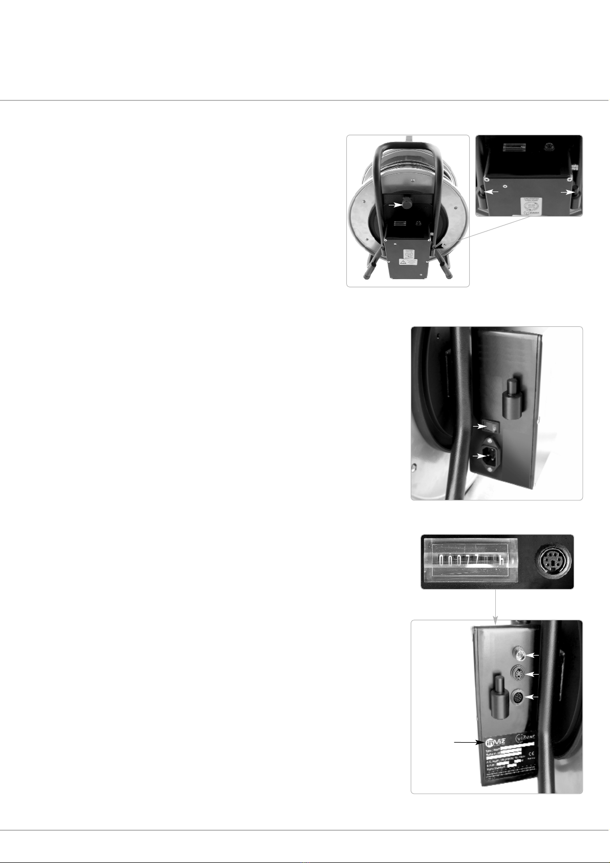
1 ‚Power cord’
2 ‚On / off main switch’
1 ‚Reel brake’
2 ‚Mount for accessory pouch’
or battery
1 ‚Counter operation hrs’
2 ‚PS2 keyboard for option text generator’
3 ‚S-Video video out (only in combination with
option data display modul’
4 ‚BNC composite video out’
5 ‚Connector umbilical to LCD’
6 ‚Date of manufacturing, SN’
2
1
3
4
5
6
1
2
2 2
1
1.1g
1.1h
1.1i
4.2 4.3
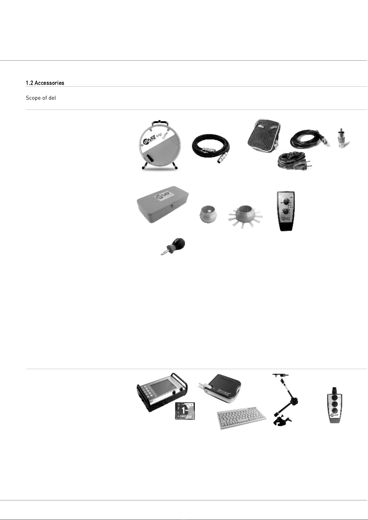
1.2 Accessories
Scope of delivery version basic device in
optional transport:
1 INVIZ big
2 Umbilical cord for LCD or
of the simple operation pendant
3 Accessory pouch with
3.1 Power cord D, UK or US
3.2 BNC Video cord
3.3 BNC to RCA video adapter
4 Accessory box
4.1 Screwdriver
4.2 Protection ring (Ø 40mm)
4.3 Centering brush (Ø 65mm)
5 Light control
Scope of delivery optional accessory
packed in optional transport case:
1 LCD operating pendant with digital
image video recorder and actual high
speed “ lash Card” Memory Card
2 lash Card reader with USB connector
3 Mini PS2 keyboard US or D
4 Magic Arm
5 Remote control for recording of
picture and video
www.vizaar.com 04
Connection and operation of the text
generator is represented in the following
chapters.
Optional pushing aid tools cannot be
accommodated in the transport case. The
usage is explained separately.
Connection and operation of the optional
LCD imaging recorder represented separate-
ly.
1
2
33.2
3.1
4
4.1
5
12
3
45
3.3

1.3 Initial operation
After connecting the power cord, the
device can be started with the red main
switch. The camera LED will be started. or
visualization of the camera image, at least
a conventional monitor or the imaging
recorder must be connected to the video
output of the device.
The device must be operated exclusively
in environments, which guarantee that
the in-built ventilator supplies the lamp
with sufficient fresh air for cooling. In
case of insufficient cooling, there can be
damage to the LED.
Example
The following is recommended for visualization:
:: Standard studio monitor, type CRT
(best results) 10” to 21”
::
INVIZ
image recorder
:: LCD monitors
:: ast laptop / Notebook via high-value
framegrabber (Status 2006 USB
framegrabber cannot be recommended)
:: Head up display
or storage of image and video, the
following are recommended given the
current state of technology:
:: VHS recorder (adequate quality only in
S-VHS operation)
:: DVD / hard disc recorder
:: Mini DV Camcorder with AV input
:: ast laptop / notebook via high value
framegrabber (s per status 2006, USB
2.0 framegrabber cannot be
recommended), e.g. ire Wire / PCMCIA
::
INVIZ
image recorder
www.vizaar.com 05
Please contact your viZaar representant for any further question to this important issue.
or avoiding possible damages to the
monitor, it is recommended to operate
the inspection camera or external periphe-
real devices like monitor or video recor-
der via the same main power potential.
This is ensured for all participating users
through the use of a multiplug. In case
very long video cords are used, there can
be disturbing equalizing current via the
shielding of the cable.
The video image of the camera head can
now be captured as so-called Composite
Signal (“video signal” in common parlan-
ce) via the lateral BNC video output
through every conventional televisionwith
Scart/AV input. The S-VHS (Y/C) output lying
thereunder offers a visibly improved quali-
ty in the detail of the image signal and
can be used with accordingly higher value
devices.
In order to use the full image quality of
the high-resolution camera quality, we
recommend that accordingly high resoluti-
on special monitors from a screen size of
10” onwards be used exclusively for
inspection tasks in the material test, which,
also possess an S-VHS input.
All video connection cords to periphereal
devices must exhibit a resistance of 75
Ohm and are characterized by the identi-
fication RG 59. Beside the industrial BNC
connector, the so-called CGA / RCA /
Cinch connectors are widely popular; corre-
sponding adapter and/or adapter cable
can be ordered in the trade.
As a rule, recording device and monitor
are switched in series, for being able to
control the recording results easily. Older
video devices do not terminate the video
line automatically with a 75 Ohm terminating
resistance. This must be placed in the
correct position manually by means of a
switch. You may refer to the instructions
of the respective devices. A wrongly set
or missing terminating resistor and/or
the parallel operation of several termina-
ted users at one output can lead to signifi-
cantly dark or overexposed pictures, it
can lead to colour distortions and can
lead to so-called ghost images in extre-
Video out Video inVideo out Video in
Monitor
DVD recorder
Option:
Image recorder Light control
INVIZ
camera system
1.3a

me cases.
However, the S-VHS output (if available),
the composite output and the LCD
tableau can be operated simultaneously.
The result and the correct interpretation
of an inspection are dependent to a high
degree on the selection of adequate
sighting and documentation medium a too
low resolution, like in case of normal TV
sets, cheap LCD head-up displays or
standard VHS recorders as well as a
faulty colour settings as a rule lead to the
missing of small material errors like e.g.
tears. The same can occur with so-called
digital systems, which partly exhibit
significant detail errors through data
compression or falsify the finest pixels of
the camera during digitalization. The
manufacturer or your dealer will gladly
advise you.
Avoid visual inspections under the
influence of sunlight on the screen.
The connection of any kind of power
supply units at the video outputs can
destroy your video endoscope.
BNC connectors and cables are widely
popular in all industrialized countries
with the most diverse signals and voltage
ranges – before start-up, confirm the
compatibility with your device by
consulting an expert.
Always consider the videosignal-norm of
your
INVIZ
system (PAL or NTSC), which
should comply to the video standard of
your country. Only NTSC or PAL monitors
/ VCR’s will allow to correctly operate
with your INVIZ scope. The INVIZ LCD
image
recorder will allow to run on NTSC and
PAL through it’s integrated auto-detect
function.
www.vizaar.com 06

1.4 urther functions of the basic device
With the delivery of an
INVIZ
system
without imaging recorder, there is a
remote control serially delivered for the
manual control of light emission
strength, or the revolving speed of the
motorized side view mirrors. The remote
control is connected to the the basic devi-
ce by means of the enclosed cord, while
the device is in off mode.
Manual light intensity adjustment
In most of the cases, it is sufficient to
leave the light emission at maximum setting,
since the automatic exposure time con-
trol of the camera (“shutter”) ensures an
optimally exposed picture. In case of spe-
cial applications, like e.g. polished metal sur-
faces, a manual intervention and/or
reduction of the light emission output
becomes necessary.
Motorised regulator “Speed”
All necessary information pertaining to
this can be found in the special section of
instructions manual option +motorized
head’.
Operating hours counter
The operating hours counter cannot be
reseted to zero. Its gives you an indication
of the progressive ageing of the probe.
Through the operating hours counter, you
shall obtain objective values for a realistic
estimate of the economic success of your
inspection work with the system.
PS2 connection socket in the control device
To the extent that the optional text generator
is integrated, the mini keyboard included
with the delivery or another keyboard can
be connected here with PS2 interface.
Alternatively, there is another interface
available in the optional imaging recorder;
but only one of the two connection points
can be occupied for trouble-free operation.
Reel brake
or transport, the reel brake ought to be
pulled carefully, in order to prevent an
unintentional rolling away of the endosco-
pe. Pulling it too hard can damage the
reel axis or the brake itself. or optimum
work, the brake can be pulled slightly or
completely during operation.
Mount for the accessory pouch
The accessory pouch can be simply hung
from the two mounting points and for
local transport, it ought to be fitted with
everything which would be needed for the
next inspection (centering tools, side view
optics, cable etc.). Remove the pouch
before storage in the case and pack
separately.
astening axis for the
variable mounting arm
At this point, the “magic arm” for
fastening the LCD imaging recorder can
ideally be fastened securely. Watch out,
since during a too great deviation of
theadjustable centre of gravity, it is
possible that the entire unit topples and
the device is damaged.
www.vizaar.com 07
1.4b
1.4a
1.4d
1.4c
1.4c

www.vizaar.com 08
1.5 ocusing
:: Rotate front housing until desired
focus is set.
:: Hold back section, while rotating
front housing.
:: Do not remove front housing
unnecessarily. LED will shut-off at
nearest fokal point.
1.5a
:: Clockwise:
focus farther
:: Conter clockwise:
focus near

INVIZ big
:: CCD push camera for visual
inspections of tube, pipes and other
cavities.
:: PAL or NTSC composite video out
(see product label).
:: Probe length 30 meter, 50 meter,
80 meter (see product label).
:: Camera head diameter 29,0 mm.
:: Weight incl. 30 meter probe
15,7kg (incl. monitor 1,4kg).
:: Recommended area of application:
40mm tubing up to 400mm pipes.
:: CCD image resolution:
NTSC: vertical 512 / horizontal 492 Pixel,
PAL: vertical 500 / horizontal 582 Pixel,
380 TV lines.
:: Min. illumination requirement: 1,5 lux.
:: Automatic white balance modus.
:: Ambient operation temperature:
-25°C – 55°C / -13° – 131° .
:: Ambient storage temperature:
-25°C – 55°C / -13° – 131° .
:: Max. operation temperature range of
the probe in air:
-10°C – 65°C / 14° – 145° .
:: Adjustable focus range:
Straight view 18mm to infinity.
:: ield of view OV:
Diagonal 72°.
:: Watertight up to 50 meter
(
CAUTION:
When using 80 meter probe!)
2 Product specifications
www.vizaar.com 09
:: big

3.1 Option push poles and pushing rods
The inspection push camera INVIZ big
usually can’t be operated within tubes
and pipes when not employing 1,5 meter
push poles with connector or endless
push rods stored on a reel.
The epoxy – fibre poles will allow the
operator to push the camera head to
most of the regions of interest of an indu-
strial device without opening it.
Even the poles and rods will provide
excellent handling advantage during the
inspection, a few precautions must be
observed to guarantee working safety and
keep the device / facillity undamaged.
Push poles and rods are hard-wearing, however will
not withstand any pushing or pulling force. The epoxy
fibre material will break when bended too much. The
allowed maximum bending depends on the design
(stiff , medium , soft ). Epoxy fibre poles are aging
rapidly through high temperatures, chemicals, sol-
vents and frequent usage. The older they are, the
more they have to be exchanged by new material.
viZaar rejects any damage compensation in the descri-
bed case of damage. In case of doubt, please send in
the pushing-aid material for evaluation to the
viZaar service.
10mm stainless steel pole connecting clutches are
especially glued onto the fibre epxoxy material, and
can be pulled-off when mistreated or worn out. Pulled
off / damaged connectors or clutches will cause
tremendous trouble to the facility, when camera head
and other poles may left in a pipe after a 90° bend.
Always check the pole connectors before employing
them to the camera. viZaar rejects any damage
compensation in the described case of damage.
In case of doubt, please send in the pushing-aid
material for evaluation to the viZaar service.
Always confirm when using the 10mm stainless steel
pole connectors, that the clutches are truly locked,
liked described in the below pictures. Open connectors
will cause the same impact as broken / defective
connectors to the object of inspection.
Damaged epoxy – fibre material can cause heavy injury
to your hand, when the PE- outside coating is worn or
damaged!
When using endless push poles stored on a reel be
aware of unexpected force trying to unwind the reel
itself when just opening the reel-break. The rod will
unwind itself in a fast and powerful way, causing injury
to people or damage to the facility!
Even without breaking, the employment of push poles
can disable you to retrieve the camera – head with the
poles from the inspected piping. viZaar rejects any
damage compensation in this case. Employing epoxy
fibre poles and rods is an issue of experience and
training. In case of doubt, please ask viZaar for further
training or technical assistance. Never push the
probe / fibre epoxy pole into the pipe applying high
force, especially through 90° bends!
3 Supplementary equipment
www.vizaar.com 10
3.1

3 Supplementary equipment
www.vizaar.com 11
3.1e 3.1f
3.1a
confirm pin locked
3.1b
3.1d
3.1c
Employing the poles or rods extremely
depends on the experience of the
operator. The different flexibility of the
rods / poles may be used depending on
the application length and number of
bends. Rods and poles can be combined,
also poles of different flexibillity may be
combined to reach the area of interest. If
the probe or camera head needs to be
rotated, 1,5 meter poles need to be used
instead of the reel.
The poles / rod can be connected to the
camera head or to the centering tool.
use screwdriver to unlock
connect to camera head
break
store connector
here
disconnect from camera head
3.1

www.vizaar.com 12
3.2 Option centering tools and trollies
Centering tools are necessary to perform
inspections with the INVIZ big in larger
tubes and pipes, nevertheless, a side view
or a straight view is employed. Centering
tools prevent the probe from lying on the
tube/pipe-sole, creating diffculties because
of unacceptable illumination and focusing
situations. Also centering tools prevent
the probe optics to get dirty through
debris in the empty pipe.
or good inspection results, always try to
attach a corresponding centering tool to
each tube diameter.
Two different centering tools technics are
available: ‘Sliding’ centering discs and
brushes for small diameters and larger
centering trollies with wheels reducing
friction. Pushing aids like epoxy fibre
rods or poles are attached to the bigger
trollies or directly to the probe when
using smaller discs only.
Standard centering tools
3 Supplementary equipment
Custom made centering tools
3.2a 3.2b
tighten 2 worm-screws
tighten 2 worm-screws
3.2g
3.2h
3.2i
3.2j
tighten 3 worm-screws
29mm head
open screws to attach or remove centering tool
3.2
When choosing a centering
tool always consider
obstacles, big weldings,
damaged (oval) pipes, dirt
etc. which decreases the
nominal inner pipe diame-
ter. Ignoring the rule to
choose centering tools at a
maximum of 75% - 85% of
the inner tube diameter may
end into the impact of the
probe get stuck inside the
inspection application.
Always assure all
components screws of the
centering tools are perfectly
tightened to not get lost
inside the application.
Heavy centering tools can
cause damage to delicate
tube surfaces.
Table of contents
Other viZaar Analytical Instrument manuals


Popular Analytical Instrument manuals by other brands


DART SYSTEMS
DART SYSTEMS MINI DARTEYE user guide

Parkside
Parkside PKIK 4.3 A1 Operating instructions and safety instructions

Parkside
Parkside PMML 5 A1 Operation and safety notes

LaserLiner
LaserLiner DistanceMaster Compact manual

Bosch
Bosch Professional GIC 12V-5-27 C Original instructions

Whistler
Whistler IC-3409PX user manual