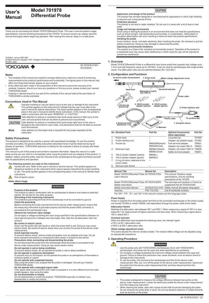
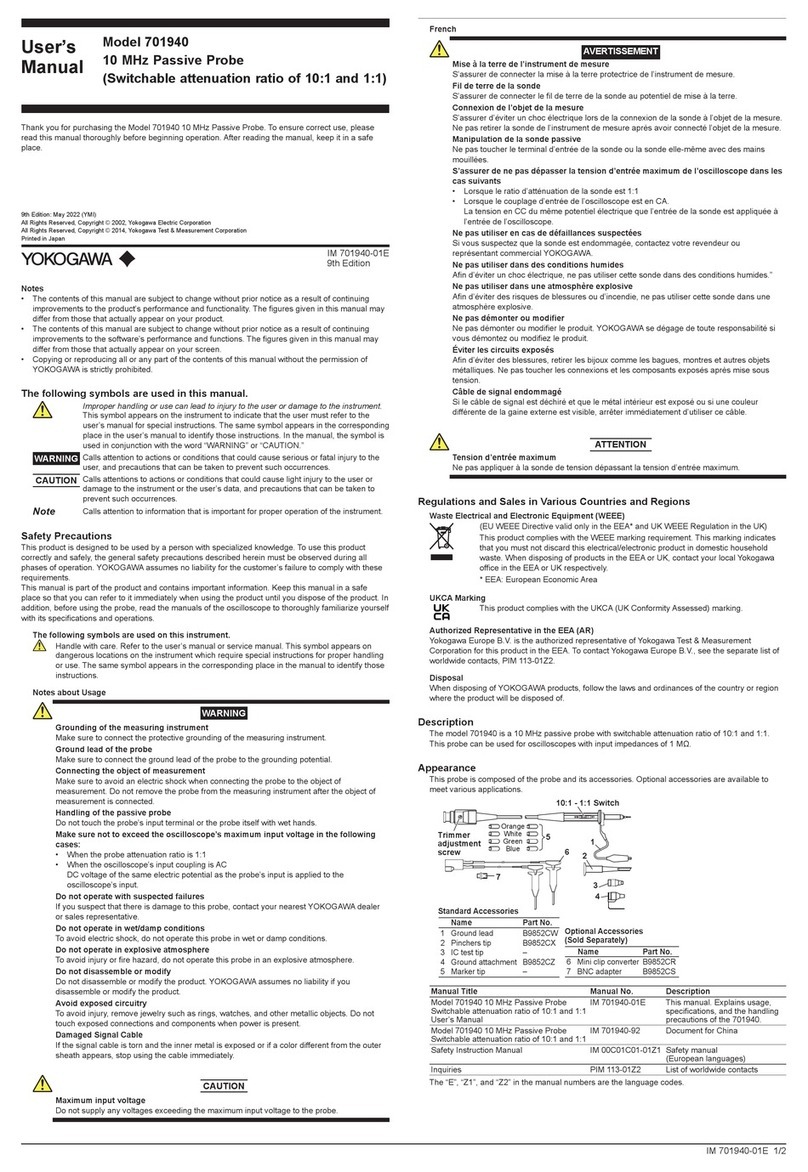
YOKOGAWA MG8G User manual

User’s
Manual Model MG8G
Paramagnetic Oxygen Analyzer
IM 11P03A03-01E
IM 11P03A03-01E
6th Edition

i
IM 11P03A03-01E 6th Edition : Jan. 26, 2022-00
uIntroduction
Thank you for purchasing the MG8G Paramagnetic Oxygen Analyzer.
Please read the following respective documents before installing and using the MG8G
Paramagnetic Oxygen Analyzer.
The related documents are as follows.
* the “E” in the document number is the language code.
General Specications
Model MG8G (General Purpose) Paramagnetic Oxygen Analyzer GS 11P03A03-01E
User’s Manual
Model MG8G Paramagnetic Oxygen Analyzer IM 11P03A03-01E (this manual)
lPrecaution in Unpacking
This analyzer is a precision instrument. Beware of the eect of shock on the analyzer, especially
while unpacking, and avoid dropping it or letting it hit another object.
CAUTION
The product is very heavy (approx. 18 kg). Handle it with care. Be sure not to accidentally drop it.
Handle it safely to avoid injury.
l Check of Model Name and Specications
The nameplate on the inside of the converter door shows the main items. Check to see if the
specications are as specied.
WARNING
Depending on the measurement gas, even the very small mount have the potential of the cause
of the accident and the inuence on the human body(such as:Burning, explosion, the toxicity,
odor-related acridity, polymerization-related degradability, corrosion).
By appropriate setting and plumbing, be careful not to have the inhalation to the human body and
the stay of dangerous gas, poisonous gases enough.
WARNING
Use cable with a durable temperature of at least 70°C.
WARNING
Please do not disassemble and remodel.
It cause Electric shock, failure, ignition, and gas leak.
Media No. IM 11P03A03-01E 6th Edition : Jan. 2022 (YK)
All Rights Reserved Copyright © 1989, Yokogawa Electric Corporation

ii
IM 11P03A03-01E 6th Edition : Jan. 26, 2022-00
u Safety Precautions
n Safety, Protection, and Modication of the Product
• In order to protect the system controlled by the product and the product itself and ensure
safe operation, observe the safety precautions described in this user’s manual. We assume
no liability for safety if users fail to observe these instructions when operating the product.
• If this instrument is used in a manner not specied in this user’s manual, the protection
provided by this instrument may be impaired.
• If any protection or safety circuit is required for the system controlled by the product or for
the product itself, prepare it separately.
• Be sure to use the spare parts approved by Yokogawa Electric Corporation (hereafter
simply referred to as YOKOGAWA) when replacing parts or consumables.
• Modication of the product is strictly prohibited.
• The following safety symbols are used on the product as well as in this manual.
WARNING
This symbol indicates that an operator must follow the instructions laid out in this manual in order
to avoid the risks, for the human body, of injury, electric shock, or fatalities. The manual describes
what special care the operator must take to avoid such risks.
CAUTION
This symbol indicates that the operator must refer to the instructions in this manual in order to
prevent the instrument (hardware) or software from being damaged, or a system failure from
occurring.
CAUTION
This symbol gives information essential for understanding the operations and functions.
NOTE
This symbol indicates information that complements the present topic.
This symbol indicates Protective Ground Terminal.
This symbol indicates Function Ground Terminal. Do not use this terminal as the protective
ground terminal.
n Notes on Handling User’s Manuals
• Please hand over the user’s manuals to your end users so that they can keep the user’s
manuals on hand for convenient reference.
• Please read the information thoroughly before using the product.
• The purpose of these user’s manuals is not to warrant that the product is well suited to any
particular purpose but rather to describe the functional details of the product.
• No part of the user’s manuals may be transferred or reproduced without prior written
consent from YOKOGAWA.
• YOKOGAWA reserves the right to make improvements in the user’s manuals and product at
any time, without notice or obligation.
• If you have any questions, or you nd mistakes or omissions in the user’s manuals, please
contact our sales representative or your local distributor.

iii
IM 11P03A03-01E 6th Edition : Jan. 26, 2022-00
n Drawing Conventions
Some drawings may be partially emphasized, simplied, or omitted, for the convenience of
description.
Some screen images depicted in the user’s manual may have dierent display positions or
character types (e.g., the upper / lower case). Also note that some of the images contained in this
user’s manual are display examples.
n Warning and Disclaimer
The product is provided on an “as is” basis. YOKOGAWA shall have neither liability nor
responsibility to any person or entity with respect to any direct or indirect loss or damage arising
from using the product or any defect of the product that YOKOGAWA can not predict in advance.
n Trademark Acknowledgments
We do not use TM or ® mark to indicate those trademarks or registered trademarks in this user’s
manual.

Blank Page

Toc-1
IM 11P03A03-01E 6th Edition : Jan. 26, 2022-00
Model MG8G
Paramagnetic Oxygen Analyzer
IM 11P03A03-01E 6th Edition
CONTENTS
uIntroduction....................................................................................................i
u Safety Precautions .......................................................................................ii
1. OVERVIEW ................................................................................................ 1-1
2. SPECIFICATIONS ..................................................................................... 2-1
3. INSTALLATION ......................................................................................... 3-1
3.1 Installation Location ......................................................................................... 3-1
3.2 Installation Procedure ...................................................................................... 3-1
3.2.1 Panel mounting.................................................................................. 3-1
3.2.2 Wall mounting .................................................................................... 3-2
3.3 Piping ................................................................................................................. 3-2
4. WIRING ...................................................................................................... 4-1
4.1 External Connection Terminals....................................................................... 4-1
4.2 Wiring Precautions ........................................................................................... 4-1
4.3 Cable Specications......................................................................................... 4-2
4.4 External Wiring.................................................................................................. 4-2
4.4.1 Power Wiring and Grounding............................................................. 4-2
4.4.2 Analog Output Wiring......................................................................... 4-3
4.4.3 Wiring for Solenoid Valves for Automatic Calibration ........................ 4-3
4.4.4 Contact Output Wiring........................................................................ 4-4
4.4.5 Contact Input Wiring .......................................................................... 4-5
5. PREPARATIONS ....................................................................................... 5-1
5.1 Adjustment of the Level in the Sensor Unit ................................................... 5-1
5.2 Setting the Auxiliary Gas Pressure................................................................. 5-2
5.3 Checking Sample Gas ...................................................................................... 5-2
6. OPERATIONS............................................................................................ 6-1
6.1 Operation Keys ................................................................................................. 6-1
6.2 Displays and Indicators.................................................................................... 6-2
6.3 Basic Operations .............................................................................................. 6-2
6.3.1 Switching from MEAS Mode to MAINT Mode ................................... 6-2
6.3.2 Entering the Password....................................................................... 6-3
6.3.3 Changing the Function Number......................................................... 6-3
6.3.4 Returning to MEAS Mode from MAINT mode ................................... 6-3
6.3.5 Entering Values.................................................................................. 6-4

Toc-2
IM 11P03A03-01E 6th Edition : Jan. 26, 2022-00
6.3.6 Selecting Data.................................................................................... 6-5
6.3.7 Functions Numbers............................................................................ 6-6
7. START-UP.................................................................................................. 7-1
7.1 Supplying Power............................................................................................... 7-1
7.2 Warm-up............................................................................................................. 7-2
7.3 Analog Output Loop Check ............................................................................. 7-2
7.4 Setting the Output Range................................................................................. 7-3
7.5 Executing Calibrations..................................................................................... 7-3
7.5.1 Calibration Gas Requirements .......................................................... 7-3
7.5.2 Setting Calibration Gas Concentrations ............................................ 7-3
7.5.3 Manual Calibration............................................................................. 7-3
8. PARAMETER SETTINGS ......................................................................... 8-1
8.1 Output Hold ....................................................................................................... 8-1
8.1.1 Setting the Output Hold Function During Calibration ........................ 8-1
8.1.2 Setting the Output Hold Function When an Error Occurs ................. 8-2
8.2 Setting the Fail Contact.................................................................................... 8-2
8.3 Action of the Maintenance Status Contact .................................................... 8-2
8.4 Setting the High/Low Limit Alarms ................................................................. 8-3
8.5 Setting the Remote Range ............................................................................... 8-3
8.6 Setting the Range Switching Answerback Contact Output ......................... 8-4
9. CALIBRATION........................................................................................... 9-1
9.1 Overview ............................................................................................................ 9-1
9.2 Calibration Coecient...................................................................................... 9-1
9.2.1 Zero Calibration Coecient ............................................................... 9-1
9.2.2 Span Calibration Coecient .............................................................. 9-1
9.2.3 Checking the Calibration Coecients................................................ 9-2
9.2.4 Initializing the Calibration Coecients............................................... 9-2
9.3 Executing Calibrations..................................................................................... 9-2
9.3.1 Manual Calibration............................................................................. 9-2
9.3.2 Semiautomatic Calibration................................................................. 9-3
9.3.3 Automatic Calibration......................................................................... 9-4
10. OTHER FUNCTIONS............................................................................... 10-1
10.1 Checking the Temperature of the Constant Temperature Chamber (Function
No. 30) .............................................................................................................. 10-1
10.2 Checking the Sensor EMF (Function No. 31)............................................... 10-1
10.3 Manual Operation of the Solenoid Valves for Automatic Calibration (Function
No. 58) .............................................................................................................. 10-1
10.4 Checking the Firmware Version (Function No. 98) ..................................... 10-1
10.5 Initializing Parameters (Function No. 99) ..................................................... 10-1
11. INSPECTION AND MAINTENANCE ...................................................... 11-1
11.1 Checking the Auxiliary Gas ........................................................................... 11-1
11.2 Checking the Sample Gas.............................................................................. 11-1
Toc-3
IM 11P03A03-01E 6th Edition : Jan. 26, 2022-00
11.3 Precautions When Stopping and Restarting the Operation ...................... 11-1
11.4 Fuse Replacement .......................................................................................... 11-1
11.5 Other Instructions........................................................................................... 11-2
12. TROUBLESHOOTING ............................................................................ 12-1
12.1 Errors and Remedies...................................................................................... 12-1
12.1.1 Checking the Error Code ................................................................. 12-1
12.1.2 Error Descriptions ............................................................................ 12-2
12.2 Faulty Readings During Measurement......................................................... 12-3
12.2.1 Fluctuations in Readings ................................................................. 12-3
12.2.2 Drift in Readings............................................................................... 12-3
12.2.3 Short-Term Shift in Readings........................................................... 12-3
12.3 When Calibration Cannot Be Executed........................................................ 12-4
12.4 In the Event of Power Failure......................................................................... 12-4
12.4.1 Instantaneous Power Failure........................................................... 12-4
12.4.2 When the Power Returns................................................................. 12-4
13. MEASUREMENT PRINCIPLE ................................................................ 13-1
13.1 Measurement Principle .................................................................................. 13-1
13.2 Principle of Interference-gas Compensation............................................... 13-1
Customer Maintenance Parts List.......................................CMPL 11P03A03-01E
Revision Information ...............................................................................................i

Blank Page

<1. OVERVIEW> 1-1
IM 11P03A03-01E 6th Edition : Jan. 26, 2022-00
1. OVERVIEW
This oxygen analyzer integrates a detector and a converter into one unit to continuously measure
the concentration of the oxygen in a sample gas.
The analyzing cell is almost free from the eects of co-existent gas, is highly sensitive, and has
a superior response. The detector is constructed to withstand vibration and mechanical shock
within the limits of current technology.
The converter has a large, easy-to-read digital display unit that displays oxygen concentration,
cell output voltage, constant chamber-temperature, etc. Analog output is electrically isolated
between the input and output sections.
Further, the instrument is provided with one-touch calibration and self-test functions to improve
operability, maintainability and reliability.
n Standard System Conguration
The standard system conguration of the MG8G paramagnetic oxygen analyzer is shown in
Figure 1.1. The system conguration that includes an automatic calibration option is shown in
Figure 1.1.
P
Model MG8G
Atmosphere vent
Analog output
Contact output
Contact input
Power supply
Sampling gas
Auxiliary gas
Filter Flow meter
Flow control valve
Pressure
regulator
Pressure
gauge
F2.1E.ai
Zero gas
Span gas
Figure 1.1 System Conguration Diagram
NOTE
Auxiliary gas (N2gas) is required in accordance with the measurement principle of the
instrument. Before supplying power to the instrument, be sure to introduce the auxiliary gas.

<1. OVERVIEW> 1-2
IM 11P03A03-01E 6th Edition : Jan. 26, 2022-00
n System Conguration with Automatic Calibration
P
Model MG8G
Pressure
regulator
F2.2E.ai
V V
V
V V
V
V V
V
Solenoid valve
V: Valve Pressure
gauge
Analog output
Contact output
Contact input
Power supply
Atmosphere vent
Sampling gas
Auxiliary gas
Filter Flow meter
Flow control valve
Zero gas
Span gas
Figure 1.2 System Conguration with automatic Calibration
NOTE
• For sample gases, use a normally-open solenoid valve. For other gases, use a normally-
closed solenoid valve.
• Use the other values if the solenoid valves fail.

<1. OVERVIEW> 1-3
IM 11P03A03-01E 6th Edition : Jan. 26, 2022-00
n Name of components
POWER SWITCH INSIDE
FUNCTION 表示
パス ワード
ゼロ / スパン校正
校正ガス濃度
表示内容説明
異常表示(FAIL点灯)
E
E
E
E
1 :
セル異常
2 :
高温部温度異常
3 :
アナログ部異常
4 :
メモリー 異 常
デジタル部異常
異 常 なし
1
2
状態表示
暖機中
(
n
: 温度 °C)
MAINT モード
オーバーレンジ
再校正待機中
:
:
:
:
レンジモード
レンジ選 択
出力レンジ 1
出力レンジ 2
出力レンジ 3
n n n n
ENABLE
INHIBIT
SPAN ZERO FUNC
MEAS/MAINT DECIMAL
POINT SHIFT INCR EXEC
:
:
:
:
:
:
:
:
PARAMAGNETIC OXYGEN ANALYZER
FUNC
HEATER
AUTO CAL
MRT.RANGE
AUTO RANGE
LCL RANGE
MEANS
MAINT
H-ALM
L-ALM
FAIL
DATA
OUT PUT
vol %O
2
Operation keys
F5.1E.ai
Displays and Indicators
Power switch
Fuses
Sensor Unit
(in constant
temperature chamber)
External Connection Terminals Internal PE
F0103_2.ai
Figure 1.3 Name of Components

Blank Page

<2. SPECIFICATIONS> 2-1
IM 11P03A03-01E 6th Edition : Jan. 26, 2022-00
2. SPECIFICATIONS
Measurement Object: Oxygen concentration in gaseous mixture
Measurement System: Paramagnetic system
Measurement Range: 0-5 to 0-25 vol%O2
3 ranges can be programmed arbitrarily within the above specied range.
Self-diagnostic content: Sensor unit error, Constant temperature chamber error, Analog error,
Memory error, Calibration coecient error
Analog output signal: 4 to 20mA DC (load resistance: Maximum 550Ω)
Contact output:
Contact rating; 3A at 250 VAC or 30 VDC, dry contacts
Fail; 1 point, open or closed when error occurs, user congurable
Contact is activated when sensor unit error, constant temperature
chamber error,analog error, memory error, or calibration coecient error
(when automatic or semiautomatic calibration is enabled) occurs
Maintenance status; 1 point, closed during maintenance
Range answerback or high/low alarm;
2 points, normally deenergized (open)
Range answerback or high/low alarm contact output, user selectable
Operate solenoid valve: 3 points, Switching between zero and span calibration gas and
measured gas.
Maximum load; AC 1A
Contact input:
Input specication: Contact ON: 200Ω or less, Contact OFF : 100 kΩor greater
Remote range switching: 2 points, Output ranges 1 to 3 can be switched by
external contact signal.
Calibration start: 1 point, calibration start command by external contact signal.
Calibration methods:
(1) Automatic calibration at set intervals by internal timer
(2) Semiautomatic calibration started by external contact input
(3) Manual calibration in the eld
Calibration gas:
Zero gas: N2gas
Note: Zero gas should not contain O2 gas with a concentration equal to or greater than 0.1% of the upper range value.
Span gas: Dry air (instrument air O2: 20.95 vol%) or standard gas containing O2gas with
a concentration of 80 to 100% of the span value (balance nitrogen).
Auxiliary gas pressure: N2, 180kPa (Approx. 35ml/min)
Note: Auxiliary gas should not contain O2 gas with a concentration equal to or greater than 0.1% of the upper range value.
Measurement gas condition:
Flow; 200ml/min ±10%, The gas ow rate may be less than 200ml/min
depending on the composition of the measurement gas.
Temperature; 0 to 50°C
Humidity; No moisture condensation in the ow path or the sensor.
Warm-up time: Approx. 2.5 hours
Installation condition:
Ambient temperature; -5 to 55°C
Humidity; 10 to 95%RH (No condensing)

<2. SPECIFICATIONS> 2-2
IM 11P03A03-01E 6th Edition : Jan. 26, 2022-00
Power supply:
Power supply Voltage 100 to 115 V AC;
Rated voltage range: 100 to 115 V AC
Allowable voltage range: 90 to 127 V AC
Reted frequency: 50 or 60 Hz
Allowable frequency range: 48 to 63 Hz
Power supply Voltage 200 to 240 V AC;
Rated voltage range: 200 to 240 V AC
Allowable voltage range: 180 to 264 V AC
Reted frequency: 50 or 60 Hz
Allowable frequency range: 48 to 63 Hz
Power consumption:
100 to 115 V AC; Max. 110 VA, normaly approx. 25 VA
200 to 240 V AC; Max. 125 VA, normaly approx. 35 VA
KC Marking: Korea Electromagnetic Conformity Standard
GB: GB30439 Part 1
Installation altitude: 2000 m or less
Installation category: II
Pollution degree: 2
Note: Installation category, called overvoltage category, species impulse withstand voltage. Pollution degree indicates the degree of
existence of solid, liquid, gas or other inclusions which may reduce dielectric strength.
Materials in contact with gas: SUS316 stainless steel, Fluorine-contained rubber
Line connection: Rc1/4
Conduit connection port: Ø27 hole
Installation: Indoor, panel or wall mounting
Structure: General purpose
Dimension: 406 (W) x 288 (H) x 216 (D) mm
Weight: Approx. 18 kg
l Characteristics
Repeatability: ±1% or less of F.S.
Linearity: ±1% or less of F.S.
Response time: 90% response within 3 sec. (from changing analog output at measured gas ow
rate 200 ml / min.)
Zero drift: ±1.5% or less of F.S. / Week
Span drift: ±2% or less of F.S. / Week
Temperature drift: ±1.5% or less of F.S. / 10 °C
Eects of measured gas ow rate: ±1% or less of F.S. for the rated owrate ±10%

<2. SPECIFICATIONS> 2-3
IM 11P03A03-01E 6th Edition : Jan. 26, 2022-00
n Model and Sux Code
Model Sux Code Option Description
MG8G - - - - - - - - - - - - - - - - - - - - - - - - - - - - - - - - Paramagnetic oxygen analyzer
Measurement range -M - - - - - - 0 - 5 to 25 vol% O2
Wetted material A- - - - - - SUS316,Fluorine-contained
Power supply -2
-5
- - - - - -
- - - - - -
200 - 240V AC, 50/60Hz
100 - 115V AC, 50/60Hz
Auxiliary gas -W - - - - - - N2gas
Flow rate of auxiliary gas -L - - - - - - Standard (35 ml /min)
Language -E
-J
- - - - - -
- - - - - -
English
Japanese
Auto calibration -C - - - - - - available
Style code *C - - - - - - Style *C
Note: For measurement ranges of 0-5 vol% O2 and less, the MG8E ameproof type paramagnetic oxygen analyzer may be used.
For applicability assessment, we will receive your request as a Customized Order.
STANDARD ACCESSORIES
Item Parts No. Qty Description
Fuse A1111EF 2250V 2A
Spanner G7050YZ 1for adjustment of sensor angle
Regulator G7033XF 1for Auxiliary gas
Mirror K9320CC 1for adjustment of sensor angle
User's Manual – 1 (this manual)
n External Dimensions
FUNC
HEATER
AUTO.CALL
MRT.RANGE
AUTO RANGE
LCL RANGE
MEANS
MAINT
H-ALM
L-ALM
FAIL
DATA
OUT PUT
vol %O
2
PARAMAGNETIC
OXYGEN
ANALYZER
Unit: mm
Panel thickness:
10 mm or less
Panel cut
A: Gas outlet Rc 1/4
B: Auxiliary gas inlet Rc 1/4
C: Sample gas inlet Rc 1/4
D: PURGE Rc 1/8
E: External PE M4
F: Conduit connection port dia. 27 hole
G: Conduit connection port dia. 27 hole
H: Conduit connection port dia. 27 hole
J: Conduit connection port dia. 27 hole
366
34 41 50 41
E D
F
G H
J
A B C
59
(22) 194
216
252
380
260
288
652570
3030 54
406
F3.1E.ai

Blank Page

<3. INSTALLATION> 3-1
IM 11P03A03-01E 6th Edition : Jan. 26, 2022-00
3. INSTALLATION
This chapter describes how to install the analyzer and carry out wiring and line work.
3.1 Installation Location
Take the following requirements into account when choosing the place of installation.
(1) Low vibration and mechanical shock levels.
(2) Low atmospheric corrosive gas content. If corrosive gas content is too highly, atmospheric
purge the case.
(3) Diurnal temperature dierence should be less than 15 degree C.
(4) No exposure to direct sunlight
(5) No direct exposure to high radiation heat, steam, hot air, temperatures, etc.
(6) Low electromagnetic eld eect.
Do not lay wiring parallel to power cables and wherever possible do not install the analyzer
near motor, electromagnetic relays, pumps, etc..
(7) Easy access for maintenance and inspection
3.2 Installation Procedure
This oxygen analyzer can be panel or wall mounted.
3.2.1 Panel mounting
Remove the mounting brackets attached to the side of the mainframe and insert the
mainframe into the panel through the panel cut-out. (See section 3.4 for panel cut-out size.)
Place the mounting brackets as indicated by the dotted lines in gure 6.2 and secure them to
the mainframe with bolts (M8× 10), spring washers , and plain washers .
Insert the mainframe into the panel until the mounting brackets touch the pane] and secure them
to the panel.
FUNC
HEATER
AUTOCAL
MRT.RANGE
AUTORANGE
LCLRANGE
MEANS
MAINT
H-ALM
L-ALM
FAIL
DATA
OUT PUT
vol %O
2
PARAMAGNETIC
OXYGEN
ANALYZER
F4.1.ai
1
2
3
4
5
Figure 3.1 Paramagnetic Oxygen Analyzer installation (1)

<3. INSTALLATION> 3-2
IM 11P03A03-01E 6th Edition : Jan. 26, 2022-00
3.2.2 Wall mounting
Locate the mounting brackets to the side of the mainframe as shown by the solid lines in
Figure 6.2 and fasten them with bolts (M8×10), spring washers , and plain washers <5> by
tightening the bolts lightly.
Attach the mainframe to the wall with bolts (M8 × 14) and washers so that the back of the
mainframe is in close contact with the wall; then, attach the mounting brackets to the mainframe.
FUNC
HEATER
AUTOCAL
MRT.RANGE
AUTORANGE
LCLRANGE
MEANS
MAINT
H-ALM
L-ALM
FAIL
DATA
OUTPUT
vol %O
2
PARAMAGNETIC
OXYGEN
ANALYZER
F4.2E.ai
Position of holes for installation
100
388 4-M8
Unit:mm
1
2
3
4
5
8
9
Figure 3.2 Paramagnetic Oxygen Analyzer installation (2)
3.3 Piping
CAUTION
Carefully connect the pipes so that there is no leakage from the pipe connections such as the
joints. Piping of the gas outlet, Please consider safety by components of the sample gas.
(1) Piping
The standard line diagram is shown in gure 3.3. Use 6/4 mm diameter metal tubes for lines
and connect the tubes in such a way that there are no leaks.
(2) Installation of the pressure regulator and pressure gauge
Install the pressure regulator and pressure gauge (0 to 0.4 MPa G) in the auxiliary line. Use
the pressure regulator to set a specied pressure. For pressure settings, see Section 5.2,
“Setting the Auxiliary Gas Pressure”.
(3) Caution on piping
This oxygen analyzer uses calibration gases for zero and span calibrations. Install the lines
so that the sample and calibration gases can be switched.
(4) Purge lines
If the atmosphere or sample gas contains corrosive or combustible gases or if the
atmospheric temperature is likely to rise too high, purge the instrument with clean air.
Connect a copper or stainless steel tube to the purge air inlet shown in Figure 3.4 to supply
air at a pressure of about 50 kPa G.
(5) Gas outlet (exhaust)
Gas from the instrument should be vented to the atmosphere. The gas outlet should be
designed so that the ingress of wind or rain is prevented.

<3. INSTALLATION> 3-3
IM 11P03A03-01E 6th Edition : Jan. 26, 2022-00
P
Model MG8G
Vent
Zero gas
Span gas
Sample gas
Auxiliary gas
Filter Flow meter
Flow control valve
Pressure
gauge
Pressure
regulator
F6.1E.ai
180 kPa
Figure 3.3 Line Diagram
Purge air outlet
(with blind seal)
Purge air inlet
(Rc 1/8 female thread)
(Note) Always remove the seal protecting the purge air outlet.
F6.2E.ai
Figure 3.4 Purge Air Connection
This manual suits for next models
1
Table of contents
Other YOKOGAWA Analytical Instrument manuals

YOKOGAWA
YOKOGAWA SMARTDAC+ GX10 User manual

YOKOGAWA
YOKOGAWA OX100 User manual

YOKOGAWA
YOKOGAWA 701940 User manual

YOKOGAWA
YOKOGAWA 701941 User manual

YOKOGAWA
YOKOGAWA ZR Series Specification sheet

YOKOGAWA
YOKOGAWA EXAxtZR User manual

YOKOGAWA
YOKOGAWA ZR202G User manual

YOKOGAWA
YOKOGAWA 701922 User manual

YOKOGAWA
YOKOGAWA EXAxt ZR22G Manual

YOKOGAWA
YOKOGAWA ZR22S User manual