Phillips screwdriver Drillwith drill bits:
1/2”
(12.5mm)
7/32”
(5.5mm)
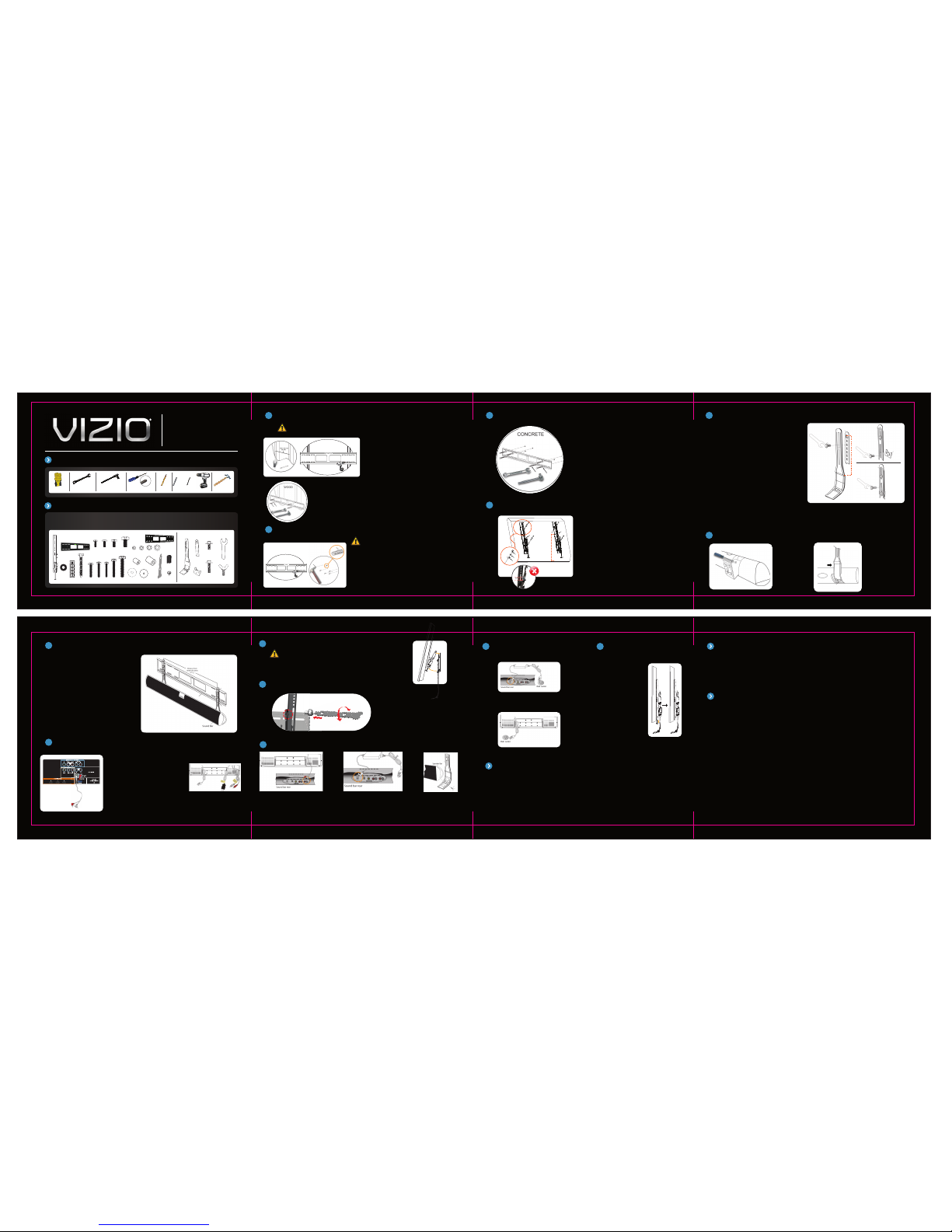
MOUNTING TO WALLS WITH WOOD STUDS
CAUTION: You must attach the TV wall mount to a wall that has at least 2” x 4” wood studs to avoid
property damage or injury.
1A
For technical assistance contact our VIZIO Technical Support
Department via email or phone.
(877) 698-4946 Fax: (949) 585-9563
Hours of operation: Monday - Friday: 6 am to 9 pm
Saturday – Sunday: 8 am to 4 pm
Please have your VIZIO model number,serial number, and
date of purchase available before you call.
VIZIO
39 Tesla • Irvine, CA 92618, USA
Telephone: (949) 428-2525 Fax: (949) 585-9514
Web: www.vizio.com
REATTACH SOUNDBAR TO BRACKETS
9
CONNECT CABLES
AND POWER
10 TIGHTEN SAFETY
SCREWS
11 TELEPHONE AND TECHNICAL SUPPORT
ONE-YEAR LIMITED WARRANTY & INSURANCE
Covers units purchased as new in United States and Puerto Rico Only VIZIO warrants for a period of
one (1) year from the date of purchase to the original purchaser of its mounting brackets, that the
bracket shall be free from defects in assembly,material, or workmanship and will repair or replace, at
its sole discretion, a defective bracket free of charge, provided the bracket is returned to VIZIO with
shipping prepaid by purchaser. Unauthorized service or repairs by anyone other than VIZIO or a
pre-approved repair facility renders this warranty void and shall release VIZIO from any further
responsibility or obligation.
Insurance: VIZIO will repair or replace up to a maximum of $10,000.00, at its option,any component
(television, projector, monitor or screen) which is damaged by aVIZIO bracket’s failure to perform*
when that product is properly installed** for its intended use. This insurance is subject to the
limitations and exclusions set forth herein.VIZIO will repair or replace the damaged television, monitor
or screen (“Components”) at VIZIO’s option, up to an amount equal to the fair market value of the
damaged Components or the original purchase price of the equipment, whichever is less, up to
$10,000.00.
Other Terms & Conditions: VIZIO reserves the right to inspect the damaged component, the VIZIO
bracket alleged to have failed, and the site where the damage occurred. DamagedComponents and
bracket must remain available forinspection until the claim is finalized. VIZIO mayrequire you to ship,
at your expense, theVIZIO bracket and damaged Component to VIZIO for inspection.VIZIO reserves the
right to negotiate the costs of repair. If VIZIO determines,in its sole discretion, that it is impractical to
ship the damaged component or bracket,VIZIO may designate, in its sole discretion, a component
repair facility to inspect and estimatethe cost to repair. The cost,if any, of shipping the Component to
and from such repair facility and of such estimateshall be borne solely by the purchaser. Whenever
claims are settled,VIZIO reserves the right to be subrogated under any existing insurance policiesthe
claimant/purchasermay have.
All above warranties and insuranceare null and void if: the VIZIO bracket in use duringthe occurrence
is not provided to VIZIOfor inspection upon VIZIO’s request at the sole expense of thepurchaser; or if
VIZIO determines that theVIZIO bracket has been improperly installed, altered in any way or tampered
with; or if it is determined by VIZIOthat the damage did not result from the VIZIO product’s failure or
that in fact no occurrence took place; or the repair or replacement of the damaged Component is
covered under a manufacturer’s warranty; or VIZIO determines thatthe Component was not used under
normal operating conditions or in accordance with any labels or instructions. Improper installation
voids this LimitedWarranty & Insurance. VIZIO’sLimited Warranty & Insurance onlyprotects against
* Failure to perform in accordance with that bracket’s specifications sheet or product manual.
** Properly installed in accordance with that bracket’s installation instruction sheet or bracket manual and only when mounted on approved surfaces.
***VIZIO reserves the right to require additional supporting evidence to substantiate any additional damage claims.
damage to properly connected and installed Components where VIZIO has determined, in its sole
discretion,that the damage resulted from a VIZIO bracket’s failure,and does not protect against acts of
God such as flood, earthquake, war, vandalism,theft, normal-use wear and tear, corrosion, misuse or
abuse. Any damage caused by failure to observe instructions for installation, or product limitations
specified in the product manualor product specification sheet, or mounting on unsuitablesurfaces will
not be covered by theVIZIO’s Limited Warranty& Insurance.
The protections described hereinshall be IN LIEU OF any other warranty, express or implied,including
but not limited to,any warranty of MERCHANTABILITY or FITNESSFOR A PARTICULAR PURPOSE.
In no event shall VIZIO be liable for incidental, special, direct, indirect consequential or multiple
damages such as, but not limitedto, lost business or profits arising out of the sale, use or inabilityto
sell or use any VIZIO products,even if advised of the possibility of damages. This LimitedWarranty &
Insurance gives you specific legal rights,and you may also have other rights, which may vary from
state to state. Some states do not allow the exclusion of limitation of incidental or consequential
damage so the above limitations maynot apply to you. This Limited Warranty& Insurance is valid only
for the original purchaser of the product and only if the original purchaser registers the purchase
on-line at www.VIZIO.comor by mailing a copy of the purchase receipt (showing the date of purchase)
and product warranty registrationcard to VIZIO, 39 Tesla,Irvine, CA 92618. All damageclaims must be
made to VIZIO within fifteen(15) days from the date of the occurrence and must be accompanied by
the purchase receiptfor the damaged bracket or this Limited Warranty & Insuranceis void. This Limited
Warranty & Insurance is onlyvalid in USA and Canada. To make a warrantyor insurance claim, please
call (877) MY VIZIO (877-698-4946)within fifteen (15) days of the occurrence. Please provideto us or
have the following informationavailable:
a.The date of the occurrence and the part number of the VIZIO bracketinvolved.
b.The Component that was used with the VIZIO bracket at the time ofthe occurrence.
c.The Component that was damaged during the occurrence and the extent ofthe damage.
d.A detailed description of any additional damage from the occurrence.***
e.A legible copy of the original receipt showing the place and date of purchaseof the
VIZIObracket.
f.A legible copy of the original receipt for the damaged Component.
g. Photo(s)of any claimed damage.
h. Serialnumber which is located on the carton box and the wall plate.
ATTACH THE SCREEN BRACKETS
2
[02] [15, 16, 17,18]
[21,22]
[06,07, 08, 09]
Wall Mount Kit
A
B
C. Anchor mount to wall
1. Using a 1/2” wrench or socket, attach the wall plate [1] to the wall with the supplied lag
bolts and washers [05] & [03].
2. Use the level before tightening bolts.
Note: It is important to make sure the wall plate is level.
Note: Do not over-tighten lag bolts. Tighten only until they are rmly against the wall plate.
C. Anchor mount to wall
1. Using a 1/2” wrench or socket, attach the wall
plate [1] to the wall with the supplied lag bolts and
washers [05] & [03].
2. Use the level before tightening bolts.
Note: It is important to make sure the wall plate is level.
Note: Do not over-tighten lag bolts. Tighten only until
they are rmly against the wall plate.
A. Locate wall studs
1. Using a stud nder, locate two wood studs that are
16” to 24” apart.
2. With a pencil, mark the location of the studs.
B. Mark and drill holes
1. Tape the included Wall Mount Template to the wall so
the holes align with the studs. Hold the wall plate [1] up
to the Wall Mount Template and use the built-in level to
make sure the Wall Mount Template is level. Put the wall
plate [1] aside.
2. Drill 4 holes with the 7/32” drill bit, 2-1/2” deep.
Remove the Wall Mount Template.
C
MOUNTING TO SOLID CONCRETE WALLS
1B
MOUNTING TO SOLID CONCRETE WALLS (continue)
1B ASSEMBLE SOUNDBAR BRACKETS
3
ATTACH SOUNDBAR BRACKET TO SOUNDBAR
4
B
C
D
Hammer
ATTACH SOUNDBAR BRACKETS TO WALL PLATE
5
CONNECT CABLES TO TV
6
A. Connect one end of the Soundbar RCA
Stereo cable to the AV1 Audio L/R jacks on the
TV. Do not connect the other end of the audio
cable to the Soundbar yet. You will do that
after the TV is mounted on the wall.
B. Connect the power cable to the back of the
TV. Do not connect the power cable to the wall
outlet yet. You will do that after the TV is
mounted on the wall.
C. See the documentation that came with the
TV to connect the cables needed for any
device (i.e. DVD player, cable box, etc.) you
want to connect to the TV. Do not connect the
other end of the cables to the devices yet. You
will do that after the TV is mounted on the wall.
TIP: Create and attach labels to
the cables, identifying the cables
to make it easier to later connect
the cables to the devices.
A. Connect the other end of the Soundbar RCA Stereo cable that is hanging down from the TV to the INPUT 1 jacks on the Soundbar.
B. Connect one end of the Soundbar AC adapter into the 24V DC jack on the back of the Soundbar.
C. See the documentation that came with the Soundbar to connect other audio devices to the Soundbar. Reattach the Soundbar to the
brackets using the wing screws [33].
Note: If the Soundbar is not levelwith the TV, slightly unscrew the screws [29 & 32]using the wrench [14] then reposition the Soundbar and re-tighten
the screws.
A. Connect the other ends of the cables that are hanging from the TV to
the appropriate devices (i.e. DVD player, cable box, etc.).
B. Connect the other end of the Soundbar AC adapter into a wall outlet.
C. Connect the other end of the TV power cable into a wall outlet.
A. Slide the TV so it is
centered over the Soundbar.
B. Tighten to safety screws
to secure using a Phillips
screwdriver.
Soundbar Bracket Kit
[27] x2
[28] x2
[29] M6
12mmx4
[30] x1
[33] x2
[32] M6
21mmv x2
[31] x2
Walltemplate
A
B
A. Mark and drill holes
1. Tape the included Wall Mount Template to the wall. Hold the wall
plate [1] up to the Wall Mount Template and use the built-in level to
make sure it is level. Put the wall plate [1] aside.
2. Drill 6 holes with a 1/2” masonry bit, 2-1/2” deep where
indicated. Remove the Wall Mount Template.
B. Install anchors
1. Install the provided anchors [04] in the holes, ush with the wall
so that the hinged end faces out.
A. Lay the TV face down on a clean, at surface.
B. Center the brackets [02] on the TV leaving a 1/2” clearance
from the bottom of the TV to the bottom of the quick release
latch. NOTE: There are two screws on the side of the quick
release latch that can be removed to adjust it’s length. Insert
screws [06, 07, 08, or 09] and washers [15, 16, 17, or 18 & 21] to
attach the top portion of the bracket to the TV.
C. Raise the bracket hinge to reveal two elongated holes that can
be used to connect the bottom portion of the bracket. Insert the
screws [06, 07, 08, or 09] and washers [15,16, 17, or 18 & 21]
anywhere along these two holes but refrain from using the lower
half portion of the top elongated hole as it interferes with the tilt
mechanism.
D. Fully tighten the screws.
E. Measure the distance from the small hole that lies to the left of
the bracket hook to the bottom of the TV. Be sure to account for
any curvature the bottom of the TV may have. This length cannot
exceed 14.5" and will be used to adjust the Soundbar bracket
length for an appropriate t.
A. When assembling the Soundbar bracket, the length from the
top of the square hole on the top bracket [28] to the indicated
lower mid-section on the curved bracket [27] should be adjusted
to equal the length measured in step 2E. The images on the right
are an example of a possible assembly setup.
B. Attach the top bracket [28] to the back of the curved bracket
[27] by inserting the short bolt [29] into any of the holes in the top
bracket. The higher the hole, the shorter the length of the overall
bracket, and vice versa. Make sure the hooks of the top bracket
[28] face away from the curved bracket [27] and point up. DO
NOT fully tighten the bolt.
C. The bracket length can be further adjusted by sliding the
brackets while the bolt is attached. Once the desired location is
obtained, fully tighten the bolt.
D. Attach the bottom bracket [31] to the back of the curved
bracket [27] by inserting the short bolt [29]. The top tip of the
bottom bracket [31] should always be placed directly beneath the
top bracket [28] unless the middle divider prevents this. Make
sure the hooks of the bottom bracket [31] face away from the
curved bracket [9] and point up. DO NOT fully tighten the bolt.
E. The long bolt [32] is used to stabilize the Soundbar and depending on your conguration can be screwed into any hole of the
top bracket [28] and may or may not go through the curved bracket [27] but it MUST make contact with the wall plate [1] behind.
DO NOT fully tighten the bolt yet.
F. Repeat the above steps with the other bracket.
A. Remove the stands
from the Soundbar by
removing the screw.
Use a Phillips screw-
driver to loosen if
needed.
B. Align the Soundbar
you assembled in the
previous step with the
outside edges of the
opening in the Soundbar
and secure with the wing
screw [33]
E
B
A. Anchor the top bracket hooks [28] to the top rail of the
wall plate [01]. Position the Soundbar to the desired
location on the wall plate.
B. Slide the bottom bracket hooks [31] up until they are
anchored on the bottom rail of the wall plate.
C. Hold the hooks rmly in place while you tighten them
with the wrench [30].
D. Tighten all of the bolts. Do not over tighten.
E. Remove the Soundbar by unscrewing the wing screws
[33]. We had you attach it to set the width of the brackets.
You will reattach it later, after the TV has been mounted.
• Follow the entire installation/user’s manual and the important safety
instructions before attempting to install or use this mounting system.
• Manufacturer is not liable for damage or injury caused by incorrect
mounting, assembly, or use.
• The mount alone fits most screens from 37” to 60”.
• This mount and Soundbar bracket bundle supports screens from 37"
to 47".
• The maximum screen and weight this mounting system can support is
60” and not more than 120 lbs (54 Kg).
IMPORTANT SAFETY INSTRUCTIONS
• Attaching a screen tha t is heavier than the maximum weight specified
above may result in instability, and possible personal injury.
• Only attach this mount system on vertical walls as instructed in
this manual.
• If you have any doubts about the ability of the wall to support the TV
and the mounting system, contact a qualified contractor.
• This product contains small items that could be a choking hazard if
swallowed.
• Keep these items away from children.
• For indoor use only.
When using this tilt mounting system, basic precautions should be followed, including:
CAUTION: Concrete anchors must be flush with the concrete surface.
ATTACH TV TO WALL PLATE
7
A. Lift the TV onto the wall plate [1].
B. Center the TV between the Soundbar brackets.
CAUTION: For safety, we recommend having two people lift the TV onto the mount.
Walltemplate
BC
SECURITY LOCK FEATURE
8
Prevent theft byapplying
security screws(key included)
[24]
[27]
[33]
[26]
[25]
[01] x1
[04]x6
[02] x2 [05]x6
[03] x6
M4x12
[06]x4
M8x16
[09]x4
M5x12
[07]x4
M6x12
[08]x4
M4x30
[10]x4
M5x30
[11]x4
M6x20
[12]x4
M8x40
[14]x4
M6x35
[13]x4
[15]x4 [16]x4 [17] x4 [18] x4
[19]x4 [20]x4
[21]x4 [22]x4
[23]x1
[24]x1
[25]x1
[26]x1
[05]
[23]
[23]
[01]
[03]
[04]
[04]
B
C
[05] [03]
[02]
[02]
BB
E
CC
[06,07, 08,09]
[15,16, 17,18]
[21]
[29]
[29]
[33]
[32]
[27] [27]
[27]
[31]
[28]
A
[01]
[31]
[28]
A
A
C