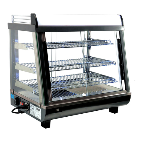
VIZU VI016 User manual

1
Perfect for displaying hot food
Available with or without Gastronorm pan
Variety of options for use
Warmer
VI016 & VI016/500W

2
WARMER SPECIFICATION PAGE
Model
VI016& VI016/500W
Dimensions
Height
Width
Depth
Machine
VI016
470mm
360mm
565mm
Machine
VI016/500W
470mm
360mm
565mm
Weight 8kg 8kg
Electrical
Running Amps
Connection Type
International
1 phase, 50Hz AC, 230v,
1Kw
4.5 Amps
2m BESCHUKO Euro cable
with, MFEUROCONVERT
Euro to UK converter plug
N/A
1 phase, 50Hz AC, 230v,
0.5Kw
2.2 Amps
2m BESCHUKO Euro cable
with, MFEUROCONVERT
Euro to UK converter plug
N/A

3
All
Vizu Warmers
have been tested and checked for proper operation before leaving the
factory.
Upon delivery please check the unit for damage. If the unit is damaged, contact the carrier,
or Fast Food Systems, immediately and file a damage claim (found in the back of the
manual) Please retain all packing materials.
Damage must be reported within 7 days of delivery.
Assembly Instructions
1. Carefully remove the two sections of the
Vizu Warmer
from the carton. You will
need a Philip’s type screwdriver to assemble. Care is needed when handling the
hood/light gantry section as lamps are fragile.
2. Along with the hood/light gantry section and the pan support section you should find
a plastic bag containing: 2-M5 x 40 stainless steel pozi screws.
3. The M5 x 40 screw now locates through the two holes on the upright part of
hood/light gantry section and will screw into the bushes in the pan support section.
4. The lamps are fitted by pushing one end of the lamp in to the lamp holder and then
clipping the other end of the lamp in to the other end of the lamp holder.
Installation
Position the
Vizu Warmer
in desired position, preferably close to a suitable electrical supply
and connect.
Operating instructions
1. Switch the heat lamp ‘ON’ using the red rocker switch.
2. Place Gastronome pan and wire into position.
3. Allow the unit to pre-heat for 20 minutes.
4. Load food into pan ready for service.
Cleaning instructions
1. Disconnect the unit from its power supply.
2. Remove the gastronome pan, wire and wash in hot soapy water.
3. Clean all stainless steel surfaces with proprietary stainless steel cleaner, such as
Sheila Shine and a soft lint free cloth.
Note: Do NOT use abrasive cleaners or pads and do NOT bleach.
4. Dry all surfaces thoroughly removing all moisture.
5. Re-connect to power supply.

4
Spare Parts Listing
PART NO. DESCRIPTION QTY. IMAGE
MFPT400200 Insert RCTI369 40 x 20mm, 1.0-2.5mm 1
MFST1235 Black insert 30mm square 6
MFIRLCAPS End caps for push-in lamp 2 E2b9
MF1000PLUGIN 1000W plug in lamp 64241015 1
MFFAS001HOT Manufacture hot labels 2
MF398-903a Heat resistant braided cable sleeve 6mm 1 Oos
MFCTB10N Single pole ceramic blocks 1
VILE14 Switch cover / bezel HD2/HD4 MFF1025 / MF1026 1
VISW17 Rocker switch HD2 Revolva HD4 MFC1553ALR 1
BESCHUKO H05Rr-F 2Mtr. Rubber C032 1
MFEUROCONVERT Euro to UK converter plug in black 19-1032 1
MF817-8877 Black Nylon 66, strain relief cable bush 1

5
Warning, when replacing bulbs
The lamps whilst being a high output unit are fragile. They must be handled with
care and they must be kept clean. Guards are fitted to prevent dirt and grease
contacting the bulbs. Grease from fingers will weaken the surface of the bulb this
will lead to fracture and failure; bulbs should always be held using gloves or a wad
of tissue to grip the bulb in.

6
ASSEMBLED
EQVILG LIGHT GANTRY
EXPLODED VIEW
45-01 HOOD
45-02 HOOD STIFFENER
45-03 VERTICAL STRUT
45-04 FIXING BRACKET
45-05 LIGHT REFLECTOR
45-06 WIRE GUARD
45-07 HOOD STIFFENER BLANK
45-08 SPACER BRACKET
MF 1000 PLUG IN, 1000W LAMP
MF 1000 HOLDER, HOLDER
MF PLATE, SERIAL PLATE
VI SW17, RED ROCKER SWITCH
VI LE14, SWITCH MEMBRANE
DRAWN BY: BECKY GRIGGS
DATE: 21/12/04
ISSUE: 03
MF 1000 HOLDER
MF 1000 PLUG IN
45-01
45-07
45-03
45-04 45-04
45-05
45-02
45-08
45-06
MF PLATE
VI SW17
VILE14

7
Fault finder
Qualified personnel must carry out any servicing.
Disconnect from power before servicing.
Problem Possible Cause Solution
Indicated ON/OFF
switch does not light-
up
No power to machine.
--------------------------
ON/OFF switch is
faulty
Check machine is
plugged in and
switch ‘ON’
Check fuse in 13a
plug.
Check circuit breaker
at mains supply.
-----------------------
Replace switch.
Heat lamp does not
light-up ON/OFF switch is in
OFF position.
ON/OFF switch is
faulty.
Heat and light lamp is
faulty.
Lamp holder is faulty.
Switch on.
Replace switch.
Replace lamp.
Replace lamp holder.

8
WIRING DIAGRAM

9
Terms and Conditions
Claims
No claim shall be entertained by the Company unless made in writing. Claims arising from
damage or partial loss in transit must reach the Company within 7 days from the date of
delivery. Claims for non-delivery must reach the Company within 10 days from the date of
dispatch. All other claims must reach the Company within 7 days. Damaged goods must be
retained for inspection/collection.
Returns
The Company does not operate a returns policy unless the goods are defective:
In circumstances where the Company agrees to accept return of goods, a charge of 25% of
the invoice value will be made.

10
Damage claim form
Machine: WARMER
Product code: VI016 or VI016/500W
Customer name……………………………………………………………
Date of delivery……………………………………………………………
Machine serial number…………………………………………………
Damage comments………………………………………………………
……………………………………………………………………………………………………………………………………
……………………………………………………………………………………………………………………………………
……………………………………………………………………………………………………………………………………
…………………………
Please indicate on the picture where the unit is damaged
Courier name…………………………………………………………………
Please cut this page out and post to
Fast Food Systems
(The address is on the back of this manual)

11
Warranty
UNITED KINGDOM AND REPUBLIC OF IRELAND
Excepting where otherwise specified all products are subject to 12 months parts and labour
warranty. Goods found defective will be repaired, credited or replaced without charge
according to the terms of the Company’s standard warranty, provided written notice is given
within the guarantee period. In no case will the company be liable for repairs made without
it’s knowledge or sanction, or for indirect damage, or any consequential loss or expense
incurred by purchasers.
Fast Food Systems Ltd, warrants to the original purchaser that the equipment supplied to be
free from defective materials or workmanship for a period of 12 (twelve) months.
The following are NOT covered by warranty:
1. Failure or breakdown caused by incorrect installation.
2. Adjustment or calibration of controls - this is a routine maintenance function.
3. Abuse or misuse, including cleaning.
4. Warranty labour is only carried out during normal working hours, calls out of hours
may be subject to surcharges.
5. The warranty will commence either on installation or 1 (one) month from date of
dispatch - whichever is the sooner.
7. Warranty on spare parts purchased for equipment outside of the warranty period is 3
(three) months from date of sale.
8. Any faulty spare parts replaced under warranty must be returned with 7 days of
supply.
9. Warranty is non-transferable.
Fast-Food-Systems Ltd
will not be held responsible, financially or otherwise, for any loss
of business as a result of equipment breakdown.

12
Fast Food Systems Limited
Manufacturer & Distributor of Catering Equipment
Unit 1 Headley Park 9 Headley Road East
Woodley Reading Berkshire RG5 4SQ
Tel: 0118 944 1100 Fax: 0118 944 0350
Email: service@fast-food-systems.co.uk
Website: www.fast-food-systems.com
ISSUE 05: 28th June 2017
MODEL NUMBER………………………………
ORDER ID/JOB NO……………………………
MACHINE SERIAL NUMBER……………………
DATE OF MANUFACTURE ……/………/………
DATE OF DELIVERY……/………/……
DATE OF COMMISSIONING……/………/……
This manual suits for next models
1
Table of contents
