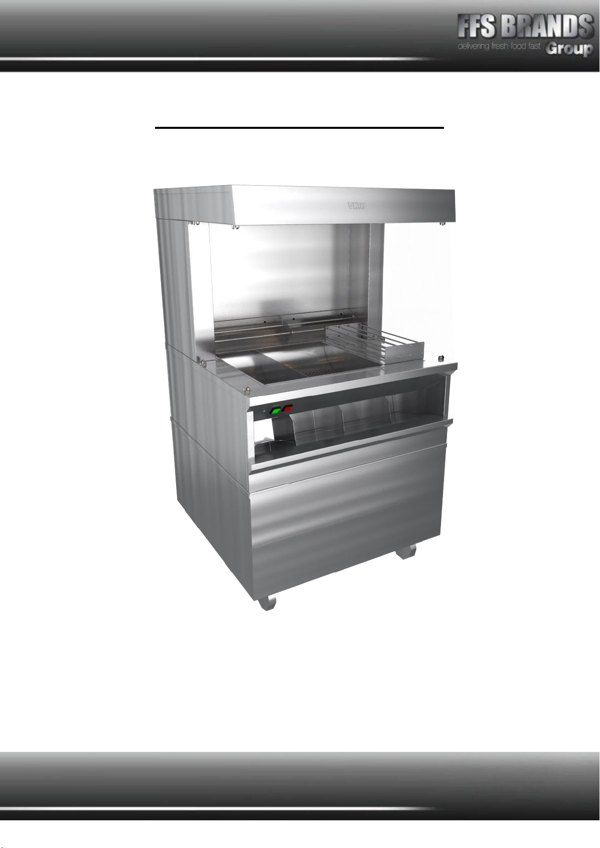
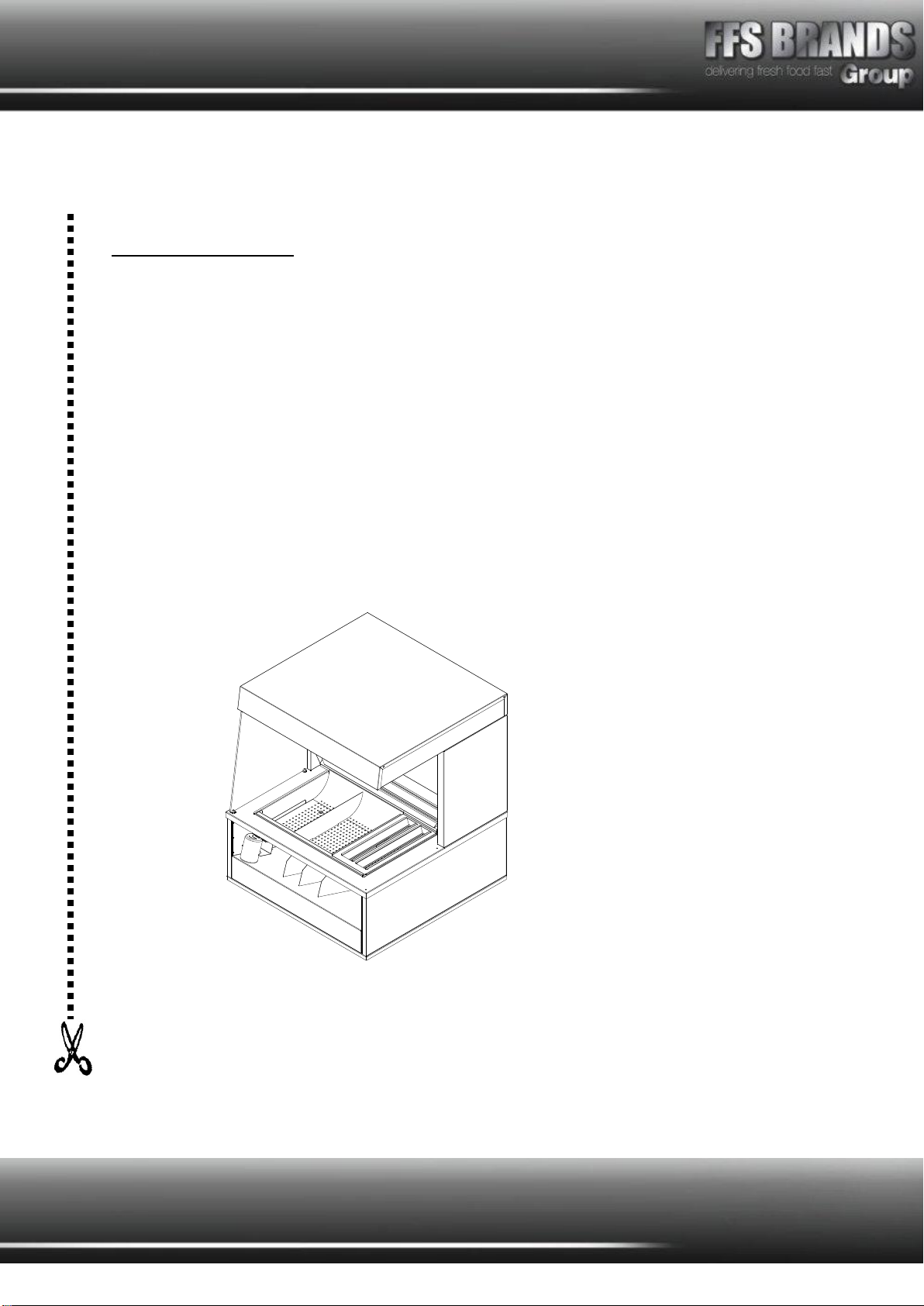
VIZU Mega Fries Topper User manual
1
Featuring tilt and clear bagging rack
Optional product rack for LH or RH use
Removable chip rack and ump for easy cleaning
Designed to fit on top of the ‘Adande’ cooling unit (shown in image)
Mega Fries Topper
VIMFTOPPER

2
MEGA FRIES TOPPER SPECIFICATION PAGE
MODEL VIMFTOPPER
Dimensions
Height
Width
Depth
Machine
1015mm
885mm
915mm
Weight
68kg
Electrical
Running Amps
Connection Type
International Option
1 phase, 50Hz AC, 230v, 2.6Kw
13 Amps
BSCHUKO 2/3 PIN PLUG
N/A

3
Assembly Instructions
Remove all packing from the unit.
Peel off all protective plastic covering from metal
Wash all removable parts in warm, soapy water and dry them thoroughly.
Installation
Your
Vizu Mega Fries Topper
unit can be set up to work either to the left or right hand side
of your fryer(s).
1. Check both heat switch and light switch are in the OFF position.
2. Firstly position the Mega Fries Topper unit in the desired position and lock both front
castors in position. Connect this to the power supply.
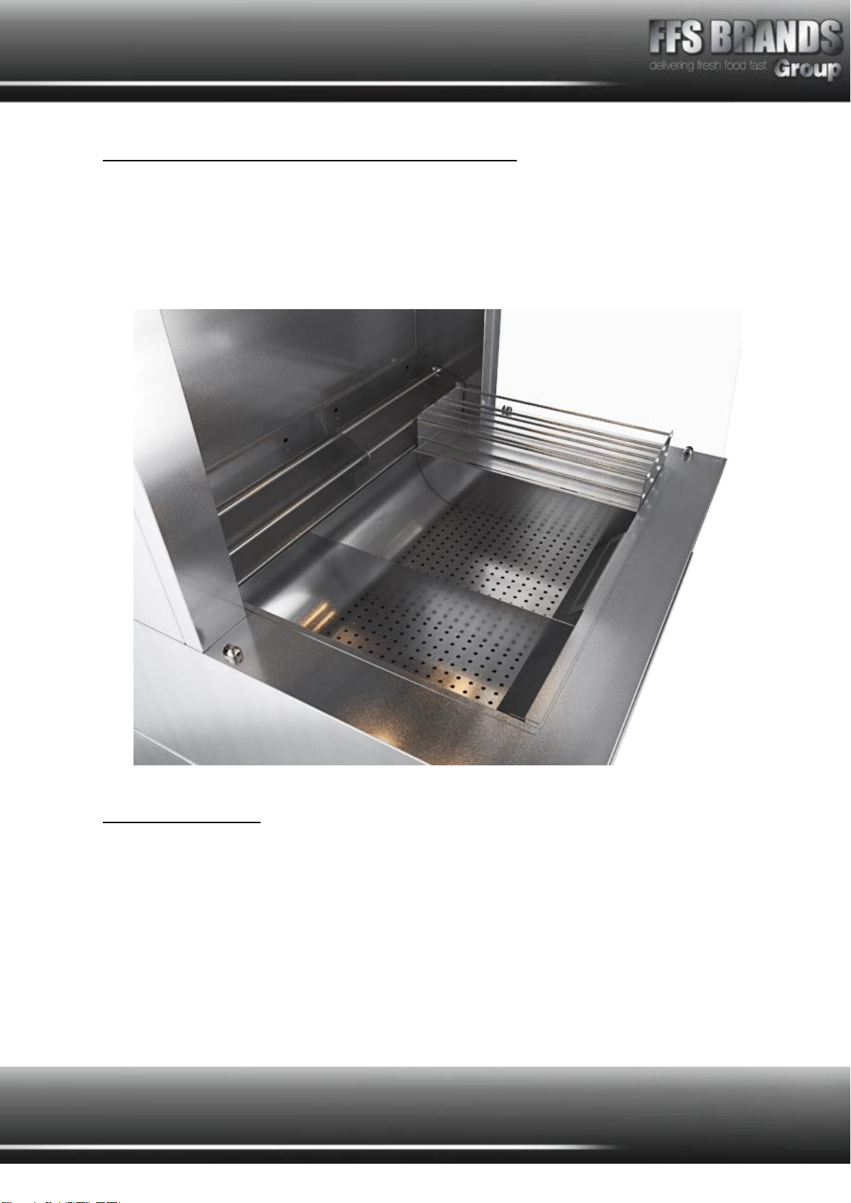
3. In order to be able to load the Mega Fries Topper unit with fries the side glass needs
to be on the opposite side of the machine to the fryer(s). If the glass needs to be
moved this is possible by unscrewing the grub screws and sliding the glass out, to
re-fit simply slide back in and tighten screws.
Operating Instructions
1. Use the switch with the red LED to start heating of the under pan element and rear
pair of heat lamps.
2. Use the switch with the green LED to light front row heat lamps.
3. Allow 20 minutes to reach operating temperature.
4. When fries are cooked lift out of oil and allow to drain.
5. When draining is complete move basket across to Mega Fries Topper serving area
and tip contents carefully into tray.
6. Take the salt shaker from its holder and add salt as desired.
7. Now using the fry scoop slide a bag/box over the bottom and scoop chips.
8. The bags full of fries can now be placed in the bagging rack prior to sale.
Note: It is important that fries are held for no longer than 10 minutes. After this time the
quality of the fries will deteriorate.
4
Additional equipment, to suit Mega Fries Topper
As well as the equipment supplied the Mega Fries Topper is fitted with two handles inside
the chip draining plate that can double up as a chip scoop holder.
1. Chip Bagging Scoop holder & handle
Cleaning: Every Day
1. ‘Switch OFF’ and remove electrical cord from power supply. Allow unit to cool
2. First of all remove the bagging rack and wash in warm soapy water
3. Next remove the chip chute and again wash in warm soapy water
4. Finally remove the perforated serving tray, wash in warm soapy water
5. Wipe the inner tray and all exterior surfaces of machines with a soft damp cloth
6. Remove side glass by unscrewing the grub screws and sliding the glass out, to re-fit
simply slide back in and tighten screws. Should be cleaned with warm soapy water
7. Dry all parts thoroughly and refit in order they were removed
5
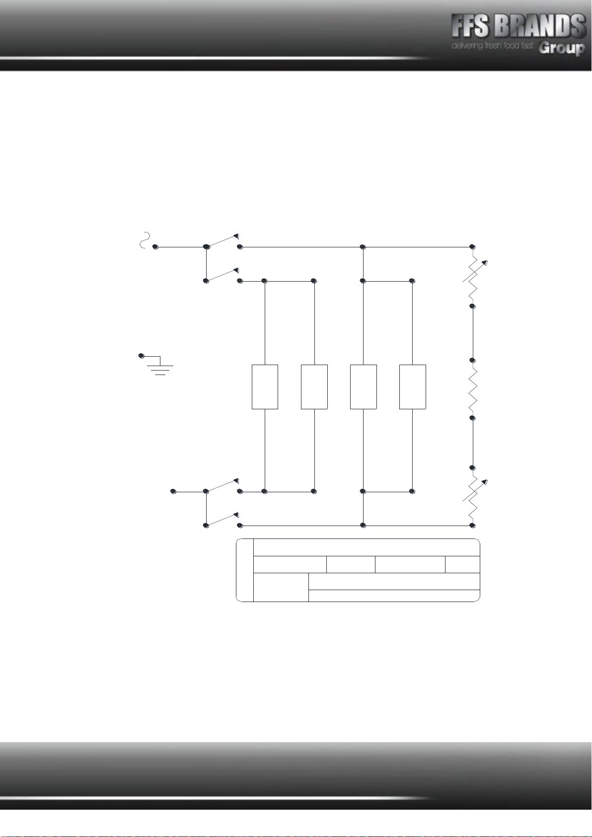
MAT ELEMENT, 500W
230V
GREEN ON/OFF
ROCKER SWITCH
48 MEGA FRIES
WIRING DIAGRAM
PROTOTYPE CODE
11/09/2014
DATE
PROTOTYPE NAME
EQVIMF 05
BUILD NO.
DRAWN DESIGNED
RT
Property of Fast Food Systems Ltd. May not be reproduced or used for
purposes other than those for which it is supplied, without written permission.
Unit 1, Headley Park 9, Headley Road East, Woodley, Reading, Berkshire. RG5 4SQ.
ENERGY REGULATOR
500W
HEAT LAMP
500W
HEAT LAMP
500W
HEAT LAMP
500W
HEAT LAMP
ENERGY REGULATOR
RED ON/OFF
ROCKER SWITCH
GREEN ON/OFF
ROCKER SWITCH
RED ON/OFF
ROCKER SWITCH
6
Spare Parts Listing
PART NO.
DESCRIPTION
QTY.
IMAGE
MF817-8877
Black Nylon 66, strain relief cable bush
1
MFE5057071010
50.57071.010 regulator + 524.010 knob
1
BESCHUKO
H05Rr-F 2Mtr. Rubber C032
1
MF88161720
Single Pole Ceramic Blocks 88161720
2
VISW15
Green neon rocker Vizu Burger/Passthru
1
VILE14
Switch cover / bezel HD2/HD4 MFF1025 / MF1026
2
VISW17
Rocker switch HD2 Revolva HD4 MFC1553ALR
1
MF374-1029
100mm low profile lens indicator 230VAC
1
MF500HOLDER
IRL500Phr Holder+Reflector For 500W Bulb
4
MFELBCE600W
590mm x 450mm 230V 500W limiter mat
1
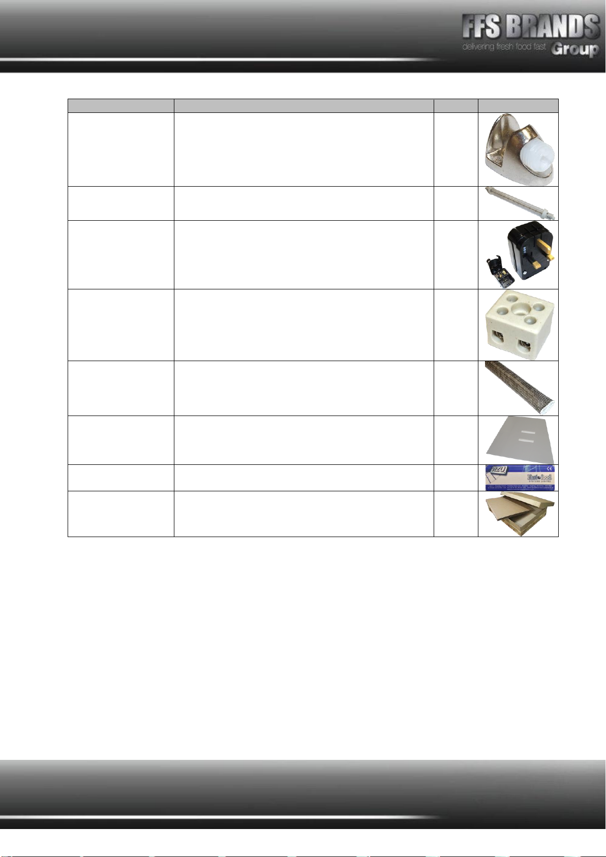
7
PART NO.
DESCRIPTION
QTY.
IMAGE
MFCOB-CR
Cob-Cr shelf support
8
MF500PLUGIN
IRL500PJ 500W JKT Lamp Plug In
4
MFEUROCONVERT
Euro to UK converterplug In black 19-1032
1
MF354Z
2 Pole 5amp term block TB06
8
MFOHSL01
High temperature sleeving
1
MFMEGAGLASS2
New Mega Fry Side Glass
1
MFCOMMON1
Label 5 140mm x 53mm
1
LPMEGACARTON
820X720X1430 0200 150K/T D/Wplain Carton
1

8
Fault Finding
Any servicing must only be carried out by qualified personnel. Machine must be removed
from electrical supply before any servicing.
Problem
Probable Cause
Solution
1. Indicated
ON/OFF switch
does not light up
No power to machine.
ON/OFF switch off
ON/OFF switch faulty
Check machine is plugged in and switched on.
Check fuse in 13a plug.
Check circuit breaker at main supply board is in
(ON).
Check Switch
Replace switch.
2. Unit will not
heat up.
No power to machine.
Red indicator switch
OFF
Red indicator switch
faulty
Thermostat faulty.
Heat element faulty
See section 1
See section 1
See section 1
Check and replace if necessary
Check and replace if necessary
3. Lights do not
illuminate
No power to machine
Green indicator switch
off
Green indicator switch
faulty
Heat lamp broken
Check machine is plugged in and switched on.
Check fuse in 13amp plug.
Check circuit breaker at main supply board is in
(ON)
Check switch
Replace switch
Replace heat lamps

9
Terms and Conditions
Claims
No claim shall be entertained by the Company unless made in writing. Claims arising from
damage or partial loss in transit must reach the Company within 7 days from the date of
delivery. Claims for non-delivery must reach the Company within 10 days from the date of
dispatch. All other claims must reach the Company within 7 days. Damaged goods must be
retained for inspection/collection.
Returns
The Company does not operate a returns policy unless the goods are defective:
In circumstances where the Company agrees to accept return of goods, a charge of 25% of
the invoice value will be made.
10
Damage claim form
Machine: MEGA FRIES TOPPER
Product code: VIMFTOPPER
Customer name……………………………………………………………
Date of delivery……………………………………………………………
Machine serial number…………………………………………………
Damage comments………………………………………………………
……………………………………………………………………………………………………………………………………
……………………………………………………………………………………………………………………………………
……………………………………………………………………………………………………………………………………
Please indicate on the picture where the unit is damaged.
Courier name…………………………………………………………………
Please cut this page out and post to
Fast Food Systems
(The address is on the back of this manual)

11
Warranty
UNITED KINGDOM AND REPUBLIC OF IRELAND
Excepting where otherwise specified all products are subject to 12 months parts and labour
warranty. Goods found defective will be repaired, credited or replaced without charge
according to the terms of the Company’s standard warranty, provided written notice is given
within the guarantee period. In no case will the company be liable for repairs made without
it’s knowledge or sanction, or for indirect damage, or any consequential loss or expense
incurred by purchasers.
Fast Food Systems Ltd, warrants to the original purchaser that the equipment supplied to be
free from defective materials or workmanship for a period of 12 (twelve) months.
The following are NOT covered by warranty:
1. Failure or breakdown caused by incorrect installation.
2. Adjustment or calibration of controls - this is a routine maintenance function.
3. Abuse or misuse, including cleaning.
4. Warranty labour is only carried out during normal working hours, calls out of hours
may be subject to surcharges.
5. The warranty will commence either on installation or 1 (one) month from date of
dispatch - whichever is the sooner.
7. Warranty on spare parts purchased for equipment outside of the warranty period is 3
(three) months from date of sale.
8. Any faulty spare parts replaced under warranty must be returned with 7 days of
supply.
9. Warranty is non-transferable.
Fast-Food-Systems Ltd
will not be held responsible, financially or otherwise, for any loss
of business as a result of equipment breakdown.
12
Fast Food Systems Limited
Manufacturer & Distributor of Catering Equipment
Unit 1 Headley Park 9 Headley Road East
Woodley Reading Berkshire RG5 4SQ
Tel: 0118 944 1100 Fax: 0118 944 0350
Website: www.fast-food-systems.com
ISSUE 6: 14.06.17
MODEL NUMBER………………………………
ORDER ID/JOB NO……………………………
MACHINE SERIAL NUMBER……………………
DATE OF MANUFACTURE ……/………/………
DATE OF DELIVERY……/………/……
DATE OF COMMISSIONING……/………/……
Table of contents


