VOGE 500AC E5 User manual

Welcome to VOGE
Thank you for choosing VOGE.
Read these operating instructions and familiarize yourself with your new vehicle so as to can
ride safely and confidently in different traffic situations. It contains important notes about operating
the vehicle and equipment, as well as important suggestions. It also contains preventive
maintenance and care instructions. if you have any questions about your vehicle, any authorized
dealer will be glad to help you.
We hope you enjoy every moment of your vehicle.
About this instruction
This instruction contains important information about the use of the vehicle, precautions, warnings
and so on. It is very important to ensure that this instruction is always kept in the car at all time. The
illustrations in this instruction may be slightly different from those in the vehicle, but the described
principle is the same. When you sell this car, please remember to hand over this instruction as it is an
important part of the vehicle. With continuous in-depth research and design improvement of
products, VOGE has always maintained the standards of high safety and quality. The manual may not
keep in line with the latest improvements of the vehicle, so the authorized dealers of VOGE will be
ready to give you correct guidance.
Executive standard of this product: Q/LX 1023-2020
This instruction to: GB/T 9969-2088 and GB/T 19678-2005
The final interpretation right of this instruction is Chongqing Longxin Locomotive Co., Ltd

The following warning symbols are highly crucial to the users. So please follow these safe
driving and maintenance procedures when you see these warning symbols.
Indicates potential hazard that could result in injury or death.
Indicates potential hazard that could result in vehicle damage.
Indicates more information to make driving easier and more convenient.
This product is only suitable for people with similar driving licence, and please driving reasonablely
and carefully .
Please pay attention to the following points:
Please do not refit the vehicle;
Please abidelocal laws and regulations;
Any refit of the device or electric appliance of this product will affect the noise, emissions and
vehicle performance, etc.
!Notice
!Danger
Important notes
Warning
!
Danger
!
With the improvement of vehicle, the condition of the real vehicle may not be the same with this manual, so
please refer to the real vehicle. Any change will be made without prior notice.

Contents
Head. . . . . . . . . . . . . . . . . . . . . . . . . . . . . . . . . . . . . . . . 1
Left side . . . . . . . . . . . . . . . . . . . . . . . . . . . . . . . . . . . . 2
Right side. . . . . . . . . . . . . . . . . . . . . . . . . . . . . . . . . . . 3
Underneath the seat . . . . . . . . . . . . . . . . . . . . . . . 4
Loading and attachment information . . . . . 5
Notes for driving . . . . . . . . . . . . . . . . . . . . . . . . . . . 6
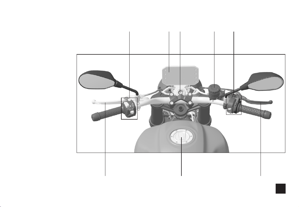
Ignition switch . . . . . . . . . . . . . . . . . . . . . . . . . . . . . 7
Gauges and indicator lights. . . . . . . . . . . . . . . . 8
Notes for refueling. . . . . . . . . . . . . . . . . . . . . . . . 14
Insufficient engine oil pressure...........15
Coolant temperature is too high . . . . . . . . . 15
Insufficient coolant . . . . . . . . . . . . . . . . . . . . . . . 16
...............17Meter interface instruction
USB Power port . . . . . . . . . . . . . . . . . . . . . . . . . . . 24
handlebar switches .......................24
Transmission pedal . . . . . . . . . . . . . . . . . . . . . . . 27
The side stand. . . . . . . . . . . . . . . . . . . . . . . . . . . . . 27
Rear brake pedal . . . . . . . . . . . . . . . . . . . . . . . . . . 27
Adjustment before driving . . . . . . . . . . . . . . . 29
Adjustment of the front brake handle . . . . 30
Adjustment of gear-shift pedal. . . . . . . . . . . 30
Adjustment of the rear brake pedal . . . . . . 31
Adjustment of throttle control handle . . . 32
Adjustment of clutch handle. . . . . . . . . . . . . . 32
Adjustment of rear shock absorber. . . . . . . 33
Adjustment of the height of headlamp . . . 33
Run-in period for motocycle. . . . . . . . . . . . . . 34
Run-in period of the engine . . . . . . . . . . . . . . 34
The run-in period of the tire . . . . . . . . . . . . . . 35
Run-in period of the braking system . . . . . 35
The driving of the motocycle . . . . . . . . . . . . . 36
The start of the engine. . . . . . . . . . . . . . . . . . . . 37
Driving on the road . . . . . . . . . . . . . . . . . . . . . . . 38
speed variators . . . . . . . . . . . . . . . . . . . . . . . . . . . 39
Braking and parking . . . . . . . . . . . . . . . . . . . . . . 39

ABS System. . . . . . . . . . . . . . . . . . . . . . . . . . . . . . . . 40
Fuel. . . . . . . . . . . . . . . . . . . . . . . . . . . . . . . . . . . . . . . . 42
Fuel evaporation . . . . . . . . . . . . . . . . . . . . . . . . . . 43
three-way catalyst . . . . . . . . . . . . . . . . . . . . . . . . 44
Troubleshooting . . . . . . . . . . . . . . . . . . . . . . . . . . 44
Fail to start the engine . . . . . . . . . . . . . . . . . . . . 44
Difficulty starting the engine . . . . . . . . . . . . . 45
Weakness of the engine . . . . . . . . . . . . . . . . . . 45
Inspection and maintenance . . . . . . . . . . . . . 46
Air filter maintenance. . . . . . . . . . . . . . . . . . . . . 49
Engine oil maintenance. . . . . . . . . . . . . . . . . . . 50
Inspection of engine oil level height . . . . . 50
........................52Change Engine Oil
. . . . . . . . . 53Change Engine Oil Filter Element
.............................54Fill Engine Oil
. 55Maintenance and Inspection of Coolant
. . . . . . . . . . . . . . . . . . 56Replacement of Coolant
. . . . . . . . . . . . . . . 58Maintenance of Brake Fluid
Maintenance of Drive Chain . . . . . . . . . . . . . . 59
. . . . . . . . . . . . . . . . 60Adjustment of Drive Chain
aintenance of Tire. . . . . . . . . . . . . . . . . . . . . . . 61M
. . . . . . . . . . . . . . . . . . . . . . . . . . . . . . . . . . . . . . . 63Fuse
. . . . . . . . . . . . . . . . . . . . . . . . . . . . . . . . . . 65Brake Pad
Replace the fuel filter . . . . . . . . . . . . . . . . . . . . . 66
. . . . . . . . . . . . . . 67Replacement of Signal Light
. . . . . . . . . 68Storage and Cleaning of Vehicles
. . . . . . . . . . . . . . 70Alterations and Accessories
The motorcycle parameters . . . . . . . . . . . . . . 71
Maintenance plan. . . . . . . . . . . . . . . . . . . . . . . . . 73
electrical schematic diagram . . . . . . . . . . . . . 74

Head
1
267
5
3
1 4 8
1.Clutch handle
2.Left brake switch
3. Gauge
4.Fuel tank lock
5.Ignition switch
6.Front brake main oil
cup
7.Right brake switch
and the oiler
8. Front brake handle

Left side
9
15 11
12
1 0
13
2
14
9.Thermostat
10.Coolant injection port
11.Shift arm
12.Lateral support
13.Engine oil drain bolt
14. Vehicle label
15.Front disc brake pump

Right side
21
1716
2223 18
3
20
19
16.Rearbrake oil cup
17.Water temperature sensor
18.Oil pressure sensor
19.Vehicleidentification number(VIN)
20. Engine type and manufacturing number
21.Radiatorfilling
22. Engine oil
filter
23.Engine speed sensor

Underneath the seat
24.Fuse box
25.Flasher
26.Battery anode
27.Accumulator
28.Electrical box
29.Toppling switch
30.ABS controller
31.Battery cathode
32.Starting relay
33.Supplementary relay
34.Diagnose interface
24 27 29
30
32
34
35
36 33
28
4
25 26
31
35.ECU
36.Tools
4 way fuse and control relay diagram(There are 6 branches
for motorcycle power supply, which get power for positive
pole of battery and with 1 fuse each, who are independent
without interference.)
3~5A about50W
2A about30A
4.5~6A about67W
F3 10A
F2 10A
F1 15A
Fan relay
K3
12
345
14
13
12
15
8
7
6
5
11
10
Grey/Red
Grey/White
Purple
Brown/Green
Brown/Black
Purple
Brown/Red
ECU P45
ECU P46
ECU P14
ECU P33
Fan 10A 15A
25A 30A
Fuel pump relay
K2
1
3
2
5
4
Main relay
12
5
4
3
K1
3 4 1 2 9
Red/White 1 Red Red Red
Red/White 1
F1 30A F2 10A
Red 2
Circuit of ABS,
Lighting and Signal
3~30A Red/White
Battery jar
starting relay
starting dynamo
Electric start button
ignition lock
Black
White/Red
White/Blue
F3 25A
F4 10A
Black
ABS
Black
right handle flameout switch
ECU P32
Black
Green/Pink
1
34
5
2
Circuit of main relay
Circuit of oil pump
Circuit of Cooling fan
Specification of safety insert:
Original interior drawing of electrical parts box
Purple Purple Purple
Oil pump
ECU, oxygen se nsor,
Diagno se interf ace,
carbon c anister,
fuel spr ay nozzle ,
FBT
Black/White
Black Lighting and signal system
Lamps, instruments,
speakers
Green/Red
White/Black
Red/White1
Red/White1
Red/White 1
Clutch
Switch
Neutral SW
Light green/Red
Green/Red
Yellow/Red
Lat eral s uppor t
fla meou t
ECU P8

Loading and attachment information
Incorrect loading, improper refit or maintenance may cause safety hazard; Ensure your
vehicle is not overloaded and follow these instructions.
Always use the original parts from VOGE and the accessories that we approved;Non-original parts,
improper installation of accessories or loading, etc will affect the performance vehicle, even result
in a violation of the law. Please be responsible for your own safety and the safety of others.
Our parts and accessories for this car have been specially designed and verified, so we
highly recommend the original parts from VOGE and the accessories that we approved.
Any change of the whole weight of the vehicle will have a great impact on the dynamic performance,
so you must accept the stipulated weight of the cargo, the number of passengers and the installation
of accessories.
!Danger
!Warinng
5

Notes for driving
1、Passengers must be familiar with the peculiarities of this vehicle. The improper positions of the
passenger s seat, such as the deviation of gravity center of passengers and the sudden movement, '
may affect the control of the vehicle. Therefore, passengers need to stay in the seats as smoothly as
possible to avoid affecting the driver. Animals are not allowed to be with driver.
2、In order to reduce the impact on the gravity center of the vehicle, all luggage carried on the vehicle
must be as low as possible. The luggage must be distributed evenly on both sides of the vehicle.
Luggage should be avoided to extend the rear parts of vehicle.
3、Luggage must be securely attached to the vehicle, and ensure it is not movable before driving.
When the vehicle feels unstable, recheck the luggage and readjust it if necessary.
4、Do not carry heavy or bulky luggage. Overload must affect the control and power performance.
5、Do not install accessories or carry luggage that degrades vehicle performance. Ensure the
function of lighting system, ground clearance, brake performance, heeling angle, driveability, tire
compression stroke, front fork working stroke and other performance.
6、Heavy handlebars or forks will affect the steering performance and cause unsafe driving.
7、Fairwater, windshield, lazyback and other large parts will affect the stability and control
performance by not only increase the weight, but also reduce the power performance. These designs
lack validation and will create insecurity.
8、Conversion to a three-wheeled vehicle is prohibited. And this vehicle can not be used for towing
trailers or other vehicles. VOGE is not liable for any damage or injury caused by the refit.
Maximum load: no more than 150kg (including driver, luggage and accessories).
6

Ignition switch
The vehicle is only equipped with a side bracket support system. In order to ensure the stability of
parking, try to turn the steering handle to the extreme left position, rather than the extreme right
position when locking the steering handle.
Do not turn the key to the " " position while the vehicle is in motion. Otherwise the vehicle
will go out of control.
Warning
!
The ignition switch is located in front of the upper panel of the fuel tank. The
ignition switch and the directional lock are integrated. The vehicle is equipped
with two keys, one of which please keep for spare. Ignition lock/direction lock,
cushion lock and fuel tank lock share one key.
The ignition lock has three positions:" "This means ignition circuit is
connected. Vehicle can be started at any time, and all the functional circuits
will be connected. The key cannot be pulled out in this position.
" " This means ignition circuit is disconnected. Vehicle can not be started.
In this position the key can be pulled out.
" " In order to lock the steering handle, please first turn the steering handle to extreme left.
Press the key down once in this position" "and then turn it counterclockwise to the " "
position. In this position the key can be pulled out. Vehicle can not be started because ignition circuit
is disconnected, and the steering handle is also locked.
Danger
!
7

Gauges and indicator lights
1.Left turn light
2.Maintenance light
3.Battery low voltage alarm
lamp
4.Fuel gauge and low fuel
warning light
5.Ice alarm
6.Environment temperature
7.Speed
8.Gear
9. Clock
10.Bluetooth
11. WIFI indicator
12.Right turn light
13.Lateral support alarm light
14.Engine fault alarm light
15.ABS fault alarm light
16.Oil pressure alarm light
17.Odograph
8
18.The speed units
19.Engine tachometer
20.Tire pressure display
21.Photosensitive sensor
22.Neutral position indicator light
23. High Beam
24. Water-thermometer and Coolant
temperature alarm light.
1
23
22
15
14
11 12
19
7
18
10
16
24
8
4
20 17
235 6 9
21
13

Turn the key to" "position, and the gauge is started for self-check:
The display lights up for self-check and shows the current vehicle status.
Engine fault alarm lamp" "ABS fault alarm lamp" "and Oil pressure alarm lamp" "light up.
Left turn light" "
When the left brake's steering switch is pushed to the left, the indicator" ",lights up.
Neutral position indicator light" N "
The engine is in neutral position, and the "N" indicator light is on.
Engine fault alarm light" "
When the engine management system of the vehicle fails, the alarm light " "lights up. When the
ignition key is turned to the" "position, the indicator " "lights up; The indicator light" "goes
out immediately after the engine starts.
!Warning
Do not wash the gauge directly with high pressure water. Please do not use gasoline, alcohol
and other organic solvents to wipe the gauge, otherwise it will cause cracks or discoloration.
!Notice
9
When the turning light is damaged or doesn’t work due to other reasons, the flashing frequency
of the indicator " " will be faster than usual, warning to check the failure of the turning light.

ABS fault alarm light" "
When the ABS system of the motorcycle fails, the indicator light" "lights up.
When the ignition key is turned to the" "position, the indicator " "lights up; The indicator light
" "goes out immediately after the engine starts.
·If the indicator light" "lights up or flashing after the engine starts, abnormal brake of wheel and
even locking will happen if you continue to use vehicle
·If the indicator light" "is always on or flashing, stop using the vehicle immediately and turn to
VOGE's authorized dealer for help as soon as possible.
!Danger
10
If the indicator light" "lights up or flashing after the engine starts, the engine may not be ignited
normally and the fuel supply system may stop supplying fuel, etc if you continue to use vehicle. If the
indicator light" "is always on or flashing, stop using the vehicle immediately and turn to VOGE's
authorized dealer for help as soon as possible.
!Warning

11
TFT display screen
Power on status: When power on, the meter displays the
information mode of the last setting.
Backlight: The meter automatically switches bright/dark
mode according to light intensity.
Bluetooth: When the mobile phone is connected to the meter
through Bluetooth, the meter can realize the call reminder
(Number+Name).
Tire pressure display: When matched with a tire pressure sensor, the meter displays the
current tire pressure of the front/rear wheels When tire pressure≤1.9bar or≥2.9bar, the tire
pressure value and the corresponding tire icon turn red for alarm.
Rotational Speed: Engine speed(r/min-rotational speed/minute—The number of turns per minute of
engine speed).
Gear: Current gear of the engine (Not in neutral).
Speed: The speed of the car(km/h-kilometer/hour , or mph-miles per hour).
Water temperature: Current coolant temperature value. (Unit: ℃ degree centigrade, Range
20℃~130℃, when temperature ≥112℃,the coolant temperature alarm lamp is on and the
temperature indicator bar turns red as a whole. Outside the range of ~ ,it displays"--"). 20℃130℃
The fuel level: Show the residual fuel at the moment.
When the fuel is about running out, the fuel level alarm light may turn yellow, which remind you the
prompt fuel filling-up.

When the turning light is damaged or does not work due to other reasons, the flashing frequency
of the indicator " "will be faster than usual, warning to check the failure of the turning light.
High Beam" "
When the High Beam switch of the left brake handle is pushed to the top, the indicator " "lights up.
Press the overtaking light on the left brake, and the indicator light" " will lights up until you release
the switch.
!Notice
Right turn" "
When the left brake's steering switch is pushed to the left, the indicator" "lights up.
12
!Danger
Taking off your hand to operate the instrument while driving will reduce the ability to control
the vehicle.
!Caution
The fuel in its tank during driving may wave, when the residual fuel is not much, the waves may
lead to the indicator bar flash. This is normal, don't worry. In case the fuel alarm light gets
yellow during driving, which indicates the capacity of residual fuel is about 3L.

Engine oil pressure light" "means the engine oil pressure is abnormal, and the engine oil
level need to be checked regularly. The only way to check the engine oil level is checking the
position of the engine oil window level height.
!Notice
!Warning
If the engine oil pressure indicator" "is always on after starting , continually use the
vehicle will harm the engine by poor lubrication due to low engine oil pressure. Stop using
the vehicle immediately and turn off the engine to check the engine oil level.
13
light" "Engine oil pressure
When the engine oil pressure is below the normal range, indicator light" "lights up.
When the ignition key is turned to the" "position, the indicator " "lights up; The indicator light
" "goes out immediately after the engine starts.

This warning light warns you to refill fuel
Caution: The insufficient fuel in its tank may lead to engine ignition failure or abnormal power output,
under this case, keep going on the ignition or driving may damage the motorcycle.
The fuel ran out in its tank is not allowed, fill up the fuel before its alarm light getting yellow.
Notes for refueling
Turn the ignition key clockwise to open
and lift the tank cap. After filling the fuel,
put the cap back in place and press the
lock cap forcefully. The key can be pulled
out when it is back in the place. When
washing the vehicle, do not use the high-
pressure water gun to wash the lock cap
of the fuel tank, preventing water from
entering the fuel tank.Please use No. 92 or above unleaded or low leaded gasoline.
Capacity of fuel tank :19LCapacity of spare tank :3L
·Fuel oil can corrode paint surface, making it discolored. If fuel oil is attached to the paint surface, it
should be immediately wiped off.
·Fuel oil will expands at high temperatures. Overfilling the tank can cause too much pressure inside
the tank and the deform or spill.
Please do not refueling beyond the bottom of the tank.
!Warning
Turn off the engine when refueling and keep away from fireworks or heat sources.
!Danger
14
21
1Oil level 2Fuel tank filler
Fuel tank cap

Insufficient engine oil pressure
This warning light is on to warn that the lubrication system pressure is too low. Stop the vehicle
immediately and turn off the engine.
Functional requirements of lubricants. lubricantsThe only way to check the level is by checking the
position of the engine oil window level height. Low engine oil level is one of the reasons the engine
oil warning light turns on. Check the engine oil level and refill the oil if the engine oil level is too low.
If the engine oil warning light is on and the engine oil level is correct, some other reason may cause
this situation. If you continue driving, these reasons may lead to engine damage. If this warning light
has been on for a long time with the correct engine oil level, stop driving and go to professional
repair sites for help as soon as possible, better at an authorized dealer.
15
Coolant temperature is too high
This warning light is on to warn that the . When the engine Coolant temperature is too high
overheats, engine damage will happen if you continue driving.
Follow instructions bellow:
Stop using the vehicle immediately and turn off the engine until the indicator light goes out. Check the
coolant and radiator after the bike cools.If the coolant level is too low, check the coolant level and
replenish the coolant.Radiator fan failure: if the coolant temperature warning light is on and the
radiator fan does not work, go to professional repair sites for help as soon as possible, better at an
authorized dealer.

This warning light is on to warn the engine failure. If you continue driving when the warning light
is on, the engine may stop working and the fuel supply system may stop supplying fuel, etc.
turn off the engine and ignition switch, and restart the engine. If the warning light goes out, then the
driving can be continued. If the warning light does not go out, please go to professional repair sites
for help.
Insufficient coolant
16
If the coolant is insufficient or the surface of the radiator is seriously blocked by sediment, the
following methods are recommended:
–Lower the heat of engine by reducing the vehicle load.
–Idle the engine and loosening the throttle in heavy traffic to avoid further temperature rise.
–If the above methods does not work, turn off the engine and go to professional repair sites for help.
Table of contents
Other VOGE Motorcycle manuals