Voith DSG-BXX113 User manual

Installation and Operating Manual
I/H Converter DSG-BXX113
2019 / 02
J.M. Voith SE & Co. KG │ Division Digital Ventures
Page: 1 / 20
918.3626018884 en
D – 74564 Crailsheim
Version: 3.3
I/H Converter
Type DSG-BXX113
Translation of the original version
Installation and Operating Manual
Version 3.3

Installation and Operating Manual
I/H Converter DSG-BXX113
2019 / 02
J.M. Voith SE & Co. KG │ Division Digital Ventures
Page: 2 / 20
918.3626018884 en
D – 74564 Crailsheim
Version: 3.3
Should you have any questions concerning the
I/H converter, please contact the Service
Department of the product group Division Digital
Ventures, J.M. Voith SE & Co. KG, Crailsheim,
indicating article number and serial number of
the I/H converter.
J.M. Voith SE & Co. KG
P.O. Box 15 55
D-74555 Crailsheim
Switchboard: +49 – 7951 / 32 - 0
Fax: +49 – 7951 / 32 - 500
Service department of the product group
Division Digital Ventures
Direct dial: +49 – 7951 / 32 - 470
Direct fax: +49 – 7951 / 32 - 605
E-mail: turcon@voith.com
Address for goods supplied:
Voith Group │ Division Digital Ventures
J.M. Voith SE & Co. KG
Voithstr. 1
D-74564 Crailsheim
This instruction manual describes the technical
condition of the I/H converter on delivery from
2019/02. Any modifications following the delivery
are not considered in this operating manual.
J.M. Voith SE & Co. KG 2019
This instruction manual is protected by copyright.
It may not be reproduced or translated in any
form or by any means (mechanical or electronic)
or submitted to third parties, without the
publisher’s written approval.
Amendment: 2019 / 02
Order No.: 918.3626018884 en
Version: 3.3
Printed in Germany

Installation and Operating Manual
I/H Converter DSG-BXX113
2019 / 02
J.M. Voith SE & Co. KG │ Division Digital Ventures
Page: 3 / 20
918.3626018884 en
D – 74564 Crailsheim
Version: 3.3
Contents
1. Technical data
2. Safety Information
2.1 Definition of notes and symbols
2.2 Proper use
2.3 Important notes
2.4 Warranty
3. Functional Description
3.1 Design
3.2 Operating characteristics
4. Packing, Storage and Transport
5. Installation
5.1 Mounting
5.2 Hydraulic connection
5.3 Electric connection
6. Commissioning
6.1 Test run
6.2 Parameter setting
7. Operation
7.1 Operation with manual operation knob
7.2 Operation with set signal
7.3 Trouble shooting and remedial action
8. Maintenance and Repair
9. Shutdown
10. Outline drawing with Wiring Diagram
11. Annex

Installation and Operating Manual
I/H Converter DSG-BXX113
2019 / 02
J.M. Voith SE & Co. KG │ Division Digital Ventures
Page: 4 / 20
918.3626018884 en
D – 74564 Crailsheim
Version: 3.3
1. Technical Data
Ambient conditions:
Ambient temperature for storage -40 °C ... +90 °C
Ambient temperature: -20 °C …+85 °C
Protection IP 65 to EN 60529
suitable for internal installation in industrial air
Electric Data:
Supply voltage 24 VDC ±15%
Power consumption approx. 0.7 A for DSG-B05..
DSG-B10
approx. 1 A for DSG-B30
max. 3 A, for t <1 sec
Setpoint input 0/4...20 mA
input resistor approx. 80 Ω with
suppressor circuit.
Hydraulic data:
Input pressure Pin min 1.5 bar + PA max for B05.. B10
5 bar + PAmax for B30
Input pressure Pin max see table
Pressure fluid mineral oil or hydraulic oil (hardly
combustible fluids on request)
Viscosity pressure fluid ISO VG 32... ISO VG 48 to
DIN 51519
Temperature pressure fluid: +10 °C...+70 °C
Oil purity recommended purity class:
To NAS1638 class 10
To ISO4406 class -/19/16
Leakage at Pin=10 bar ≤3 l/min for DSG-B05… DSG-B10
Leakage at Pin=40 bar ≤5 l/min for DSG-B30

Installation and Operating Manual
I/H Converter DSG-BXX113
2019 / 02
J.M. Voith SE & Co. KG │ Division Digital Ventures
Page: 5 / 20
918.3626018884 en
D – 74564 Crailsheim
Version: 3.3
Type
DSG- BXX 113
B05...
B07...
B10...
B30...
Output pressure
regulating range
PA[bar]
0..5 1..7 0..10 0..30
Input pressure
Pin max [bar]
40 40 40 70
Flow rate line P →A
Q1 [l/min]
at ∆P = 1 bar
24 24 23 24
Flow rate line A →T
Q2 [l/min]
at ∆P = 1 bar
30 30 28 30
Regul. range approx.
PA max [bar]
at setpoint 20 mA
3..53,5..75..10 10..30
Regul. range approx.
PAmin [bar]
at setpoint 4 mA
0..1,5
0..3 0,5..3
1..5 0..2
0..6 0..5
0..18
The regulating range of PAmin depends on the set pressure PAmax.
The regulating range of PAmin indicated above refers to the minimum adjustable
pressure PAmax.
Mechanical data:
Dimensions, fitting see chapter 10
Hydraulic connection see chapter 10
Type-depending installation position see chapter 10
Mounting position see chapter 10
Sealing material FPM
Weight approx. 12 kg

Installation and Operating Manual
I/H Converter DSG-BXX113
2019 / 02
J.M. Voith SE & Co. KG │ Division Digital Ventures
Page: 6 / 20
918.3626018884 en
D – 74564 Crailsheim
Version: 3.3
2. Safety Information
2.1 Definition of notes and symbols
Danger !
This symbol signals an imminent danger to the life and
health of individuals.
If this note is not observed, injury to health and even most
serious injuries may be the consequence.
Warning !
This symbol signals a harmful situation.
If this note is not observed, the product may be damaged.
Note !
This symbol refers to proper handling of the product. It does not refer to
or indicate a dangerous situation.
2.2 Proper use
The I/H converter serves to transform an electric set signal
into a related hydraulic output pressure reduced to feed-in pressure. This
allows, for example, adjusting control pistons at hydraulic cylinders which
are used to position the valves of steam turbines.
2.3 Important notes
The following notes refer to the entire instruction manual and have to be
observed in addition to the individual notes.
Accident prevention
•Improper use may cause operating agent under pressure to leak
at the sealing surfaces. There is a risk of fire around hot components.
•
Isolate the hydraulic supply prior to working on the I/H converter.
Installation and Operating Manual
I/H Converter DSG-BXX113
2019 / 02
J.M. Voith SE & Co. KG │ Division Digital Ventures
Page: 7 / 20
918.3626018884 en
D – 74564 Crailsheim
Version: 3.3
•Failure of electric power or disturbance of the control electronics
integrated in the I/H converter may cause strong variations of the
output pressure when operating the I/H converter. Thus e.g. the
piston rod of a hydraulic cylinder may move uncontrolled, causing
danger to individuals or equipment.
•During operation, the outer surfaces of the I/H converter may heat up
due to the pressure fluid. Contact may cause skin burns. Make sure
to cool down the I/H converter prior to working on it.
•Electrical components are installed in the I/H converter. These
components can be destroyed by e.g. electric welding in its
surrounding. Therefore make sure to disconnect all electric
connections prior to electrical weldings in the surrounding of the I/H
converter.
Environment protection
•During mounting, dismounting or improper use of the I/H converter
pressure fluid may leak out. Operating agent reaching the sewage
system or open soil, causes severe environmental damages. Leaking
pressure fluid has to be collected and deposited in accordance with
the national legal regulations.
Instruction manual
•The instruction manual contains important information for proper
handling of the I/H converter. Prior to installation and commissioning
of the I/H converter, read the manual carefully and make sure it is
completely understood.
•Keep this manual in a location convenient to the operating staff.
•In addition to this operating manual: Have the relevant regulations for
prevention of accidents and environmental protection available and
observe these.

Installation and Operating Manual
I/H Converter DSG-BXX113
2019 / 02
J.M. Voith SE & Co. KG │ Division Digital Ventures
Page: 8 / 20
918.3626018884 en
D – 74564 Crailsheim
Version: 3.3
Staff qualification:
•Only trained and instructed staff is allowed to perform any work on the
I/H converter. This personnel has to be trained and authorized to
mount I/H converters professionally.
•Installation, commissioning and operation have to be effected by an
electronic expert.
Constructional modifications:
•Mounting and constructional modifications are not permitted.
2.4 Warranty
The terms and conditions mentioned in the General Conditions
of Sale of J.M. Voith SE & Co. KG │ Division Digital Ventures,
Crailsheim, are applicable. Warranty claims are excluded, if these are
due to one or several of the following causes:
•Improper transportation, storage, mounting, set-up, commissioning
and operation of the I/H converter.
•Not observing the safety instructions and guidelines included in this
instruction manual.
•Use of spare parts not approved by
J.M. Voith SE & Co. KG │ Division Digital Ventures, Crailsheim.
Repair works on the I/H converter are to be performed or approved by
J.M. Voith SE & Co. KG │ Division Digital Ventures, Crailsheim.

Installation and Operating Manual
I/H Converter DSG-BXX113
2019 / 02
J.M. Voith SE & Co. KG │ Division Digital Ventures
Page: 9 / 20
918.3626018884 en
D – 74564 Crailsheim
Version: 3.3
3. Function
3.1 Design
Fig.: 3.1.1
1 - Control magnet VRM Pin - Input pressure
2 - Tappet for power transmission PA- Output signal pressure
3 - X0 and X1 potentiometers
4 - Manual operation knob T1- Tank return line
5 - Electric connection T2- Tank return line with int. leakage
6 - Control housing FMag - Magnetic force
7 - Control piston with damping piston FHyd - Hydraulic force
8 - Cover FFed - Spring force
9 - Control spring

Installation and Operating Manual
I/H Converter DSG-BXX113
2019 / 02
J.M. Voith SE & Co. KG │ Division Digital Ventures
Page: 10 / 20
918.3626018884 en
D – 74564 Crailsheim
Version: 3.3
3.2 Operating characteristics
(see fig. 3.1.1)
A set signal w = 4...20 mA generates a magnetic force FMag in the VRM,
the limits of which can be adjusted by means of the X0 and X1
potentiometers and which is then transmitted onto the control piston via
tappet.
The hydraulic force FHyd being proportional to the output signal pressure
PAacts against this force.
In the case of the two forces being equal, the control piston is positioned
in the “hydraulic center” as shown in fig. 3.1.1 and the output signal
pressure PAcorresponds to the set signal. In the “hydraulic center“
position the control piston performs minimum oscillating movements in
the area of the guiding edges P→PAand PA→T, in order to keep the
output pressure PAon the value set by FMag.
When increasing the set signal and thus FMag from this condition, the
control piston position changes and thus connects the output pressure PA
to the feed pressure P and blocks PAtowards the tank return line T1and
T2. Now pressure PAwill increase until the same has returned the control
piston to the “hydraulic center“ and PAcorresponds to the new set signal.
The spring force FFed of the control spring generates a force-offset in
order to guarantee the I/H converter function for output pressures of
approx. 0 bar, too.
The internal leakage is fed back into tank return line T2.
Function of manual operation knob:
The control magnet of I/H converter is provided with a manual operation
knob, by means of which an adjustable spring force can be set instead of
the magnetic force FMag . This spring force affects the control piston via
magnet armature and tappet. The hydraulic force FHyd , being
proportional to the output signal pressure PAalso acts against this spring
force here. Thus adjustment of output pressure is possible without
electric connection.
Installation and Operating Manual
I/H Converter DSG-BXX113
2019 / 02
J.M. Voith SE & Co. KG │ Division Digital Ventures
Page: 11 / 20
918.3626018884 en
D – 74564 Crailsheim
Version: 3.3
4. Packing, Storage and Transport
Packing
The I/H converter is delivered in a special packing.
The openings for the hydraulic connections are sealed with plugs to
prevent penetration of impurities and humidity.
Storage and preserving
The outer surfaces of the I/H converter are protected by means of a
preserving surface coat.
The internal parts are preserved by oil.
Within Europe the anticorrosion protection is sufficient for approx. 8
months in industrial air, presuming storage of the I/H converter in a dry
location.
In case the I/H converter is supposed to be stored for a longer period of
time, special precautions will have to be taken.
In each specific case, these precautions have to be agreed with J.M.
Voith SE & Co. KG │ Division Digital Ventures, Crailsheim.
The storage ambient conditions have to be within the limits as indicated
in chapter 1.
Transport
Improper transport may cause personal injuries and damages to
property. Pack the I/H converter in a way that prevents damages of
housing and electric connection during transport.
5. Installation
•Improper installation of the I/H converter may cause malfunctions and
premature failure of the operation of the I/H converter.
•Cleanliness is imperative during installation and connection. Prevent
that any impurities ( dust, metal chips etc.) can get into the I/H
converter. These impurities impair its function and may cause
damage to the I/H converter.
Cover and protect the I/H converter and in particular the electric lines
during construction time.
Installation and Operating Manual
I/H Converter DSG-BXX113
2019 / 02
J.M. Voith SE & Co. KG │ Division Digital Ventures
Page: 12 / 20
918.3626018884 en
D – 74564 Crailsheim
Version: 3.3
5.1 Mounting
Perform any work on the I/H converter only when it is in deenergized
condition and with switched off oil supply system.
Protect oil and power supply against unintentional switching-on during
mounting.
Install the I/H converter in accordance with the permissible installation
position as shown in chapter 10.
Recommended fastening bolts:
2 pieces hexagonal screws M10, strength category 8.8.
tightening torque MA=35 Nm, thread slightly oiled.
Select screw length according to mounting situation.
5.2 Hydraulic connection
The hydraulic connection on the I/H converter is made by means of
connection bores at its bottom. The connecting flange is sealed with
O-rings. Please refer to chapter 10 for position and dimensions of the
connections.
Surface roughness of connecting flange:
Ra = 1.6
µ
m, Rmax = 6.3
µ
m
Only pressure-less return of the operating medium through return line T2
to the tank, ensures proper work of the I/H converter.
In practise the tank lines for the connections T1 and T2 are joined
together and laid downgrade towards the tank in one common pipe line.
Requirements to this pipe line:
Nominal size 20 mm or bigger for I/H converters with an output pressure
up to 10 bar.
Nominal size 30 mm or bigger for I/H converters with an output pressure
of more than 10 bar.
Observe the correct pressure range when selecting pipes, hoses,
screwings and flanges.
Immediately replace damaged pipes and hose lines.
When assembling the pipe lines, ensure that it is fastened to fixed
structures, free from vibration and not to moving equipment. Temperature
variations of the piping (thus alterations in length) must not apply
constraining forces to the I/H converter.

Installation and Operating Manual
I/H Converter DSG-BXX113
2019 / 02
J.M. Voith SE & Co. KG │ Division Digital Ventures
Page: 13 / 20
918.3626018884 en
D – 74564 Crailsheim
Version: 3.3
Clean pipe lines from dirt, cinder, sand, chips etc. prior to installation.
Pickle or flush welded pipes.
Clean and flush carefully all pipe and hose lines prior to attaching the
I/H converter.
=> For flushing, a flushing plate (Art. No. 43.8565.10) is available.
See chapter 11.
=> To connect the I/H converter to the piping system an adapter (Art. no.
43.9300.11) is available. See chapter 11.
•Residual oil may leak when removing the plug (max. 0.1 l). Collect the
oil in a suitable container and deposit it properly.
•Do not use fibrous or hardening sealing compounds, such as e.g.
hemp or mastic to seal the connections and screwings.
5.3 Electric connection
The electric system has to be connected by an electric expert in
accordance with electrical engineering standards and legal regulations of
the manufacturing country
When connecting customer’s lines, avoid parallel run of the I/H converter
lines with the lines of current converter assemblies.
The customer’s signals and supply lines running to the I/H converter
must be screened.
=> A connecting cable with Art. No. 91876100XX can be supplied for
electric connection.
Please refer to chapter 10 for the wiring diagram.

Installation and Operating Manual
I/H Converter DSG-BXX113
2019 / 02
J.M. Voith SE & Co. KG │ Division Digital Ventures
Page: 14 / 20
918.3626018884 en
D – 74564 Crailsheim
Version: 3.3
6. Commissioning
The I/H converter was adjusted and tested at J.M. Voith SE & Co. KG │
Division Digital Ventures works by means of the potentiometers X0 and
X1. The test result is documented in an attached test certificate.
The potentiometers are provided with a protective cap to avoid
unintentional maladjustment and impurities.
6.1 Test run
Make sure that pipe lines and hydraulic system are cleaned prior to
performing a test run. The operating fluid has to be in accordance with
the purity class as indicated in chapter 1. Do not flush or clean the
pressure fluid with the I/H converter being hydraulically connected.
Operation of the I/H converter with contaminated pressure fluid is not
permitted, the I/H converter may be damaged.
•Check the line mounting, connection and flow direction to and on the
I/H converter.
•Check the electric connection.
•Switch on oil supply system and check input pressure.
•After waiting approx. 5min. switch on supply voltage 24VDC. (the
waiting period is necessary for auto-ventilation of the system during
first commissioning and after longer standtstill periods.)
The minimum input pressure has to be 1.5 bar more than the maximum
output pressure required at 20 mA.
•Set the signal w = 4.. 20mA and check output pressure.
During the test run, check all hydraulic connections for leakages. In case
of leakage, immediately switch off the hydraulic supply and eliminate
leakages.
6.2 Parameter setting
Due to unintentional maladjustment of the parameters or changed
operating conditions, new setting of one or both parameters may become
necessary.
We recommend to document adjustment of the parameters as well as the
set values.
The parameters are adjusted by means of potentiometers X0 and X1.
Please refer to chapter 10 for the position of the potentiometers.

Installation and Operating Manual
I/H Converter DSG-BXX113
2019 / 02
J.M. Voith SE & Co. KG │ Division Digital Ventures
Page: 15 / 20
918.3626018884 en
D – 74564 Crailsheim
Version: 3.3
Potentiometer effects:
X0 - With help of potentiometer X0 the minimum output pressure
PA min is adjusted at a setpoint of 4 mA.
Pressure increase by turning the potentiometer clockwise.
X1 - With help of potentiometer X1 the maximum output pressure
PA max is adjusted at a setpoint of 20 mA.
Pressure increase by turning the potentiometer clockwise
X1 should be adjusted before X0.
The X1- adjustment influences the adjustment of X0.
Manufacturer-provided adjustments:
At the works, the I/H converter has been adjusted as indicated in the
order.
7. Operation
7.1 Operation with manual knob
Operation with manually controlled rotary knob is possible without electric
energy.
On operation with manually actuated rotary knob, uncontrolled stroke
movements of the hydraulic components controlled by the I/H converter
output might occur due to the increase in the output signal pressure.
Manual operation is only possible when the circlip is removed from the
manual operation knob.
On completion of operation with manual operation knob, move the
manual operation knob in its final position by turning it counter clockwise
and pushing in the circlip in its final position.
•Remove the circlip.
•Slowly turn the manual operation knob clockwise and observe the
output pressure.
Effective direction: Output pressure increases by clockwise rotation.

Installation and Operating Manual
I/H Converter DSG-BXX113
2019 / 02
J.M. Voith SE & Co. KG │ Division Digital Ventures
Page: 16 / 20
918.3626018884 en
D – 74564 Crailsheim
Version: 3.3
7.2 Operation with set signal
When the supply voltage is switched on, the output signal pressure can
be adjusted continuously by the set signal 4...20 mA within the limits set
by the potentiometers X0 und X1.
7.3 Trouble shooting and remedial action
Prior to all works, make sure that the I/H converter was commissioned
according to chapters 5 and 6.
Malfunction: Pressure variations
The output signal pressure PAmay vary now and then or
periodically with low or high frequency and amplitude.
Cause: 1. air inclusions in the hydraulic component
2. low or considerably varying input pressure.
3. dirt particles in the hydraulic component
4. pressure on return line
Remedy: 1. On first commissioning or after longer periods of
stand still air inclusions in the hydraulic component may
cause pressure variations. Therefore, when setting into
operation again, observe to first connect the input pressure
and then, after waiting five minutes, the supply voltage. This
supports the auto-ventilation of the system.
2. Under load and in particular in case of higher output
signal pressure, low input pressure may lead to pressure
variations.
Increase and / or stabilize the input pressure by taking
appropriate measures (e.g. accumulator).
3. Contaminated pressure fluid results in increased friction at
the control piston, thus causing hysteresis and pressure
variations.
Open hydraulic component and clean the inner elements. In
case of damaged surfaces and guiding edges replace the
I/H converter.
4. The dimensions of the return line have to be sufficient.
In case of additional consumers of the output pressure
connected to this line, make sure they do not create any
pressure in the return line. See also chapter 5.2.

Installation and Operating Manual
I/H Converter DSG-BXX113
2019 / 02
J.M. Voith SE & Co. KG │ Division Digital Ventures
Page: 17 / 20
918.3626018884 en
D – 74564 Crailsheim
Version: 3.3
Malfunction: Output pressure PA
→
0 bar or
→
P (input pressure)
Due to a defective control valve VRM or blockage of the
control piston the output pressure may fall to 0 bar or
increase to the input pressure.
Remedy: The function of the component part can be checked using the
manually controlled knob with the supply voltage being
switched off. See chapter 7.1.
If the output pressure cannot be adjusted manually, the control
piston, e.g., may be blocked by particles.
Open hydraulic component and clean inner parts.
If the surfaces and guiding lines are damaged, exchange
the I/H converter.
Should output pressure adjustment be possible with manual
operation knob, but not with the control magnet, the control
magnet VRM is defective.
8. Maintenance and Repair
For trouble-free and reliable operation of the I/H converter, it is
necessary to perform inspection, maintenance and repair work in
certain intervals.
Routine inspection:
Check the pipes, screw connections and connections on the
I/H converter for leakage, impurities and damage.
Eliminate any leakage, impurity and damage noticed, if required, during
appropriate operating modes.
Monitor the control behavior of the I/H converter for any changes.
Analyse and eliminate the causes, if required, during appropriate
operating modes.

Installation and Operating Manual
I/H Converter DSG-BXX113
2019 / 02
J.M. Voith SE & Co. KG │ Division Digital Ventures
Page: 18 / 20
918.3626018884 en
D – 74564 Crailsheim
Version: 3.3
Inspection after approx. 740 operating hours / max. 1 month:
Take an oil sample from the oil tank and analyse it for solid and
suspended matters, water content, shadings and air bubbles.
Analyse oil purity of the oil sample. Clean or exchange the oil, if
required, in an appropriate operating mode.
Inspection after approx. 8000 operating hours / max. 1 year:
Take an oil sample from the oil tank and analyse it chemically.
If required, clean or change the oil during an appropriate operating mode.
Check and retighten, if necessary, the electric connections of the I/H
converter.
9. Shutdown
If the I/H converter is switched off for reasons of repair, inspection or
unit shutdown, switch off the oil supply system and relieve all pressure
reservoirs, if effective. Switch off the 24 VDC supply voltage and
remove the lines as well as piping and hose connections. Doing so, a
considerable oil quantity may leak out. Collect the oil in a suitable
container and deposit it properly. Close all holes. Now clean and pack
the I/H converter.
Disposal
In the event of disposal of the I/H converter, observe the local applicable
regulations regarding the environmental protection. The I/H converter
essentially contains steel, copper, synthetic materials, electronic
components and residual oil.
Installation and Operating Manual
I/H Converter DSG-BXX113
2019 / 02
J.M. Voith SE & Co. KG │ Division Digital Ventures
Page: 19 / 20
918.3626018884 en
D – 74564 Crailsheim
Version: 3.3
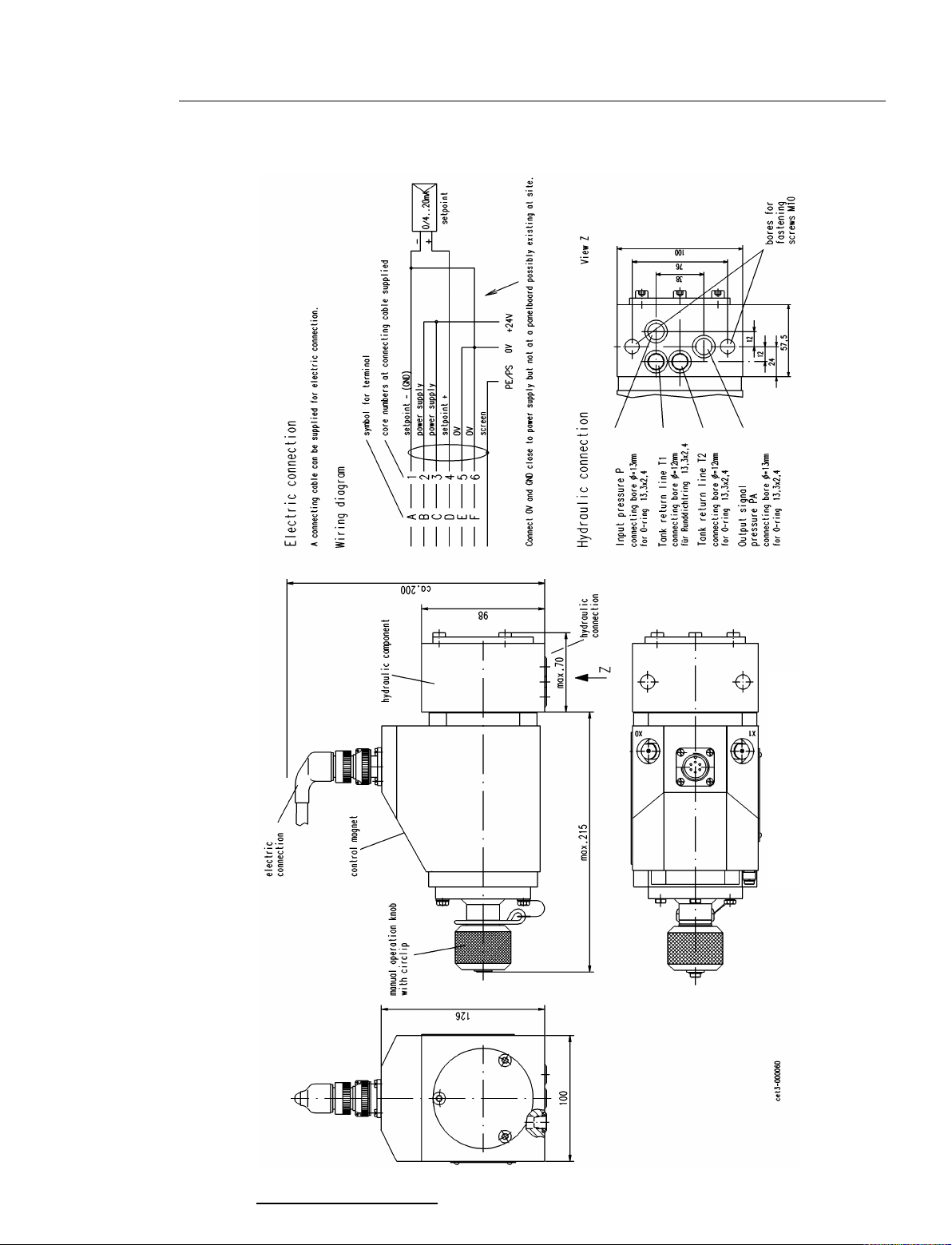
10. Outline Drawing with Wiring Diagram
Installation position B05, B07 and B10 vertical
B30 vertical, control magnet on top

Installation and Operating Manual
I/H Converter DSG-BXX113
2019 / 02
J.M. Voith SE & Co. KG │ Division Digital Ventures
Page: 20 / 20
918.3626018884 en
D – 74564 Crailsheim
Version: 3.3
11. Annex
Flushing plate 43.8565.10
Adapter plate 43.9300.11
Connecting cable 91876100XX
This manual suits for next models
5
Table of contents
Other Voith Media Converter manuals


