Electro-Craft EPS-HAV1004R User manual

Users Manual
EPS-HAV1004R
ENCODER & MODULATOR USB
ELECTROCRAFT AUSTRALIA 36 Binney Road, Marayong NSW 2148 T: (02) 8811 5155 F: (02) 9831 2139
www.electrocraft.com.au

Directory
CHAPTER1INTRODUCTION.........................................................................................................................1
1.1 PRODUCT OVERVIEW.................................................................................................................................1
1.2 KEY FEATURES...........................................................................................................................................1
1.3 SPECIFICATION...........................................................................................................................................2
1.4 PRINCIPLE CHART......................................................................................................................................2
1.5 APPEARANCE AND DESCRIPTION................................................................................................................3
CHAPTER2INSTALLATIONGUIDE.................................................................................................................5
2.1 GENERAL PRECAUTIONS............................................................................................................................5
2.2 POWER PRECAUTIONS................................................................................................................................5
2.3 DEVICE’S INSTALLATION FLOW CHART ILLUSTRATED AS FOLLOWING.........................................................5
2.4 ENVIRONMENT REQUIREMENT...................................................................................................................5
2.5 GROUNDING REQUIREMENT.......................................................................................................................6
CHAPTER3OPERATION...............................................................................................................................7
3.1 3.1 LCD MENU STRUCTURE......................................................................................................................7
3.1 INITIAL STATUS..........................................................................................................................................9
3.2 GENERAL SETTING FOR MAIN MENU..........................................................................................................9
CHAPTER4WEBNMSOPERATION...........................................................................................................177
4.1 LOGIN....................................................................................................................................................177
4.2 OPERATION............................................................................................................................................188
CHAPTER5OPERATIONOFCLOSEDCAPTION(CC).....................................................................................28
CHAPTER6OPERATIONOFLOWDELAYSETTINGS......................................................................................28
CHAPTER7APPLICATION...........................................................................................................................31
7.1 APPLICATION EXAMPLE............................................................................................................................31

1/34
Chapter1Introduction
1.1 Product Overview
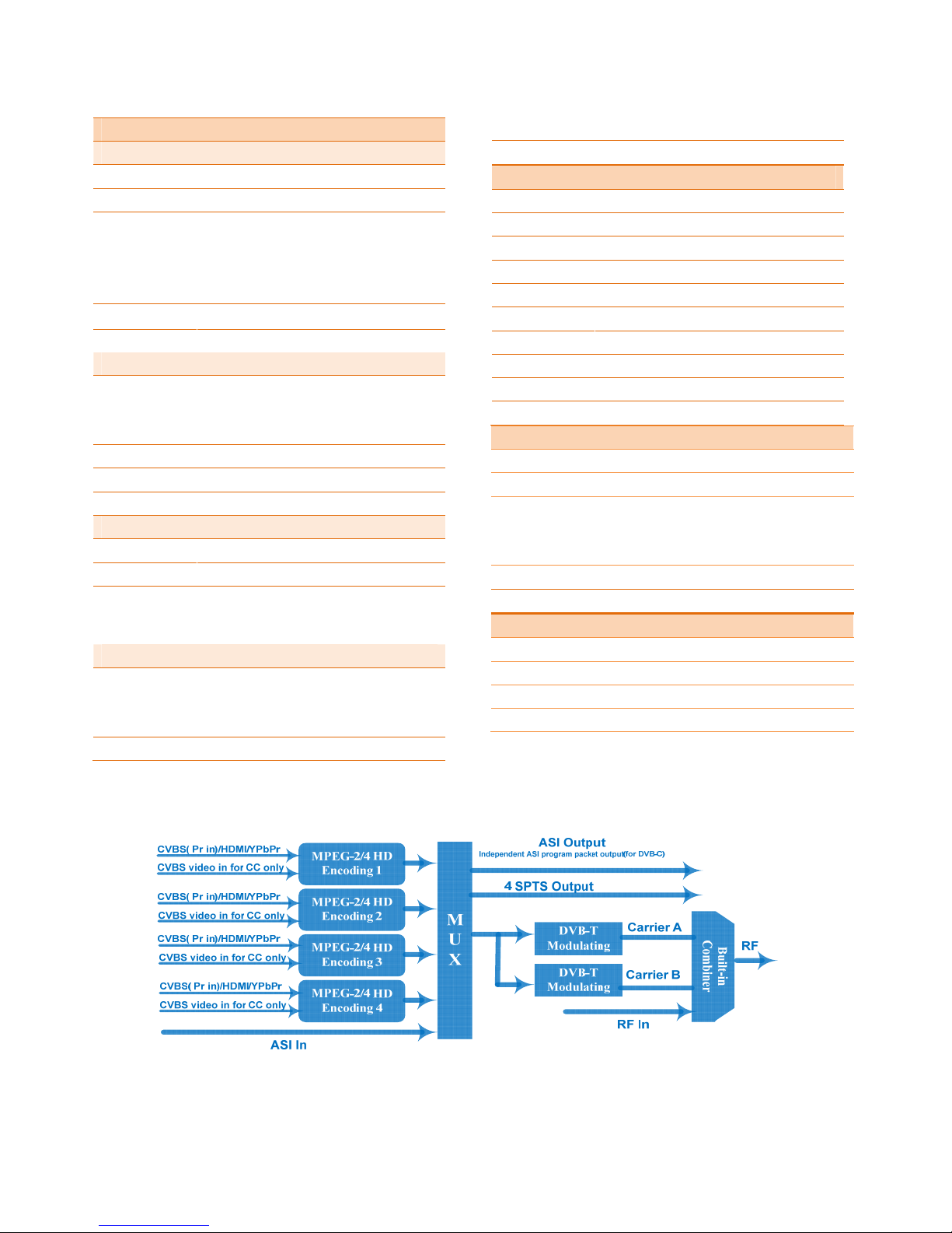
EPS-HAV1004R is a MPEG-2/MPEG-4/AVC/H.264 encoder modulator.This unit converts 4x
HDMI/AV signals into 2xDVBT RF channels within frequency range of 30-960 MHZ.It has
equipmed with 4x HDMI/AV inputs,1x ASI input,1x RF input and output,1x UDP IP port and 1x RF
port with dual DVBT carriers.
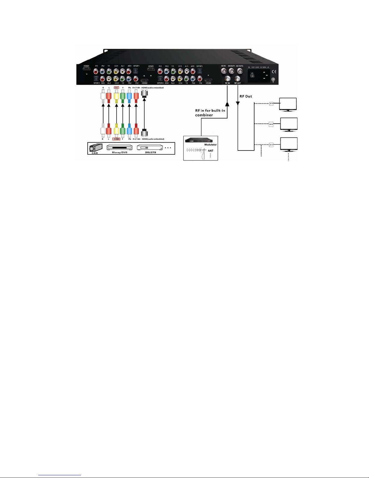
The source could be from a variety of devices including satellite receivers, closed-circuit television
cameras, Blue-ray players, and PCs etc. It is equipped with a RF input which acts as a combiner
with other RF frequencies.
This unit enables the distribution of an external source over a coax RF system.The signal from an
external source can be viewed via a terrestrial digital set top box.Typical applications include
pubs ,clubs, sporting venues ,resorts , hospitals etc.
1.2 Key features
MPEG2 HD & MPEG4 AVC H.264 HD video encoding
DD AC3 (2.0), MPEG4-AAC, MPEG2-AAC, MPEG1 Layer II audio encoding
Support DD AC3 (2.0/5.1/7.1) passthrough
4* HDMI/YPbPr/CVBS channels in
1*ASI in for re-mux; 1*RF in for RF mix
2* DVB-T RF out ;ASI out; IP out
Support CC (Closed Caption) EIA608, (from CVBS source only)
Support Low Delay
LCN (Logical Channel Number) support
Excellent modulation quality
LCD display, Remote control and firmware
Web-based NMS management; Updates via web
1.3 Specification
EncodingSection
Video(HDMI)
EncodingMPEG2;MPEG4AVC/H.264
InterfaceHDMI*4
Resolution
1920*1080_60P,1920*1080_50P(For
MPEG4AVC/H.264only),
1920*1080_60i,1920*1080_50i,
1280*720_60p,1280*720_50P
LowDelayNormal,Mode1,Mode2
AspectRatio4:3;16:9
Audio(HDMI)
EncodingMPEG1LayerII;MPEG2‐AAC;MPEG4‐AAC;
DDAC3(2.0);
DDAC3(2.0/5.1/7.1)passthrough
InterfaceHDMI*4/SPDIF*4
Samplerate48KHz
Bitrate64/96/128/192/256/320kbps
Video(YPbPr/CVBS)
EncodingMPEG2;MPEG4AVC/H.264
InterfaceCVBS/YPbPr*4(RCA)
Resolution
CVBS:720*576_50i,720*480_60i
YPbPr:1920*1080_60i,1920*1080_50i;
1280*720_60p,1280*720_50P
Audio(L/R)
EncodingMPEG1LayerII;MPEG2‐AAC;MPEG4‐AAC;
DDAC3(2.0);
DDAC3(2.0/5.1/7.1)passthrough
Interface4*Stereo/8*mono/4*SPDIF
Samplerate48KHz
Bitrate64/96/128/192/256/320kbps
DVB‐TModulatorSection(Option)
Standard EN300744
FFTmode2K,8K
Bandwidth6M,7M,8M
ConstellationQPSK,16QAM,64QAM
GuardInterval1/4,1/8,1/16,1/32
FEC1/2,2/3,3/4,5/6,7/8
MER≥42dB
RFfrequency 30~960MHz,1KHzstep
RFoutCOFDMDVB‐Tout(2carrierscombinedout)
RFoutputlevel‐30~‐10dbm(81~97dbµV),0.1dbstep
System
Localinterface LCD+controlbuttons
Remotemanagement WebNMS
StreamOut2ASImirroredout(BNCtype,100M);
IP(4SPTS)overUDP,RTP/RTSPout(RJ45,
100M)
NMSinterfaceRJ45,100M
Language English
General
PowersupplyAC100V~240V
Dimensions482*400*44mm
Weight 4.5kg
Operationtemperature0~45℃
1.4 Principle Chart

3
1.5 Appearance and Description
FrontPanelIllustration
1 2 3 4 5 6 78 9
①LCDScreen
②NMSPort
③DataPort
④PowerandAlarmIndicators
⑤TSLockIndicators
⑥UpandDown,LeftandRightButtons
⑦EnterButton:forconfirm
⑧MenuButton:forbackstep
⑨LockButton:presstolockset
RearPanelIllustration
123456789
101112
①HDMIinputport
②YPbPr/CVBS(Pr)inputport
③CVBSinputportforCConly
④L/RAudioinput(StereoorMono)
⑤SPDIFAudioinputport
⑥ASIinputport
⑦ASIOutputport1&2
⑧PowerSwitch
⑨PowersupplySlot
⑩RFinport
RFoutport
Grounding
4

5
Chapter2InstallationGuide
This section is to explain the cautions the users must know in some case that possible injure
may bring to users when it’s used or installed. For this reason, please read all details here and
make in mind before installing or using the product.
2.1 General Precautions
9Must be operated and maintained free of dust or dirt.
9The cover should be securely fastened, do not open the cover of the products when
the power is on.
9After use, securely stow away all loose cables, external antenna, and others.
2.2 Power precautions
9When you connect the power source, make sure if it may cause overload.
9Avoid operating on a wet floor in the open. Make sure the extension cable is in good
condition
9Make sure the power switch is off before you start to install the device
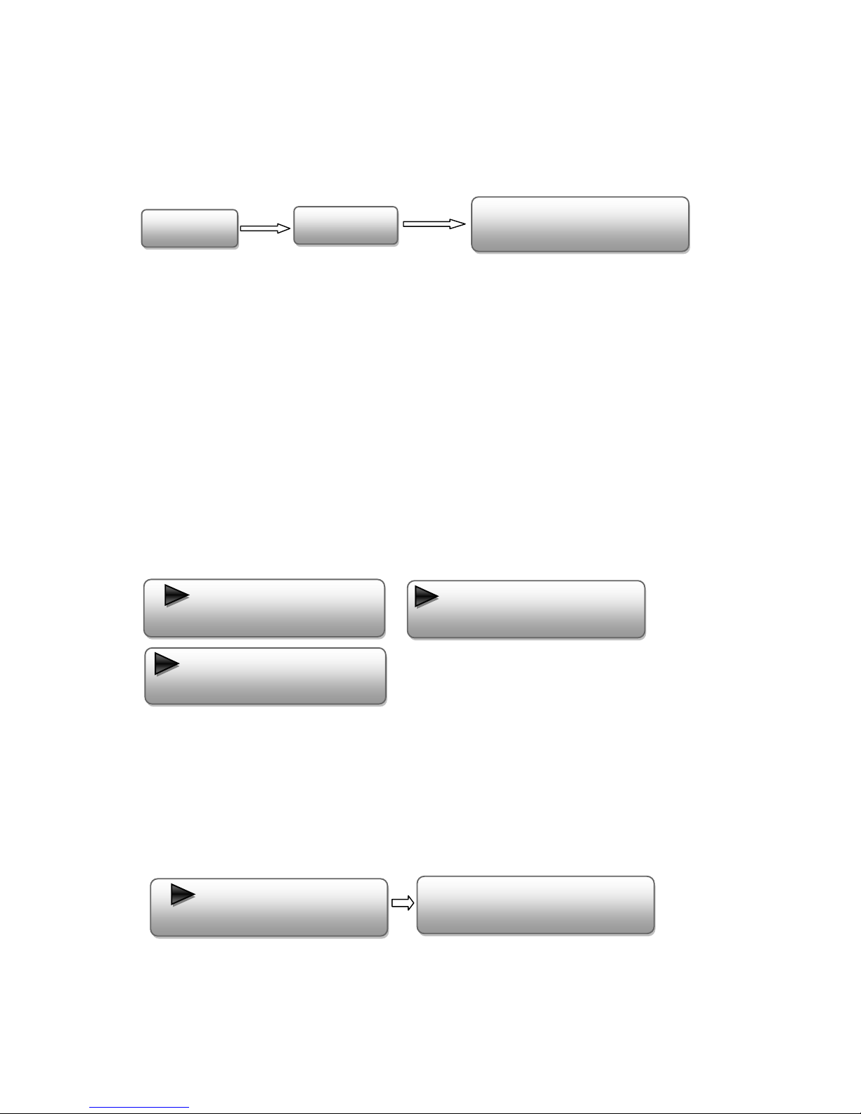
2.3 Device’s Installation Flow Chart Illustrated as following
2.4 Environment Requirement
Item Requirement
Machine Hall Space
When user installs machine frame array in one machine hall,
the distance between 2 rows of machine frames should be
1.2~1.5m and the distance against wall should be no less than

6
0.8m.
Machine Hall Floor
Electric Isolation, Dust Free
Volume resistivity of ground anti-static material:
1X10⁷~1X10¹⁰Ω,Grounding current limiting resistance: 1MΩ
(Floor bearing should be greater than 450Kg/㎡)
Environment
Temperature
5~40℃(sustainable ),0~45℃(short time),
installing air-conditioning is recommended
Relative Humidity 20%~80% sustainable 10%~90% short time
Pressure 86~105KPa
Door & Window Installing rubber strip for sealing door-gaps and dual level
glasses for window
Wall It can be covered with wallpaper, or brightness less paint.
Fire Protection Fire alarm system and extinguisher
Power
Requiring device power, air-conditioning power and lighting
power are independent to each other. Device power requires
AC 110V±10%, 50/60Hz or AC 220V±10%, 50/60Hz. Please
carefully check before running.
2.5 Grounding Requirement
9All function modules’ good grounding is the basis of reliability and stability of devices.
Also, they are the most important guarantee of lightning arresting and interference rejection.
Therefore, the system must follow this rule.
9Grounding conductor must adopt copper conductor in order to reduce high frequency
impedance, and the grounding wire must be as thick and short as possible.
9Users should make sure the 2 ends of grounding wire well electric conducted and be
antirust.
9It is prohibited to use any other device as part of grounding electric circuit
9The area of the conduction between grounding wire and device’s frame should be no
less than 25 ㎡.

7
Chapter3Operation
The front panel of EPS-HAV1004R Encoder Modulator is the user-operating interface and the
equipment can be conveniently operated and managed by user according to the procedures displayed
on the LCD:
Keyboard Function Description:
MENU: Cancel current entered value, resume previous setting; Return to previous menu.
ENTER: Activate the parameters which need modifications, or confirm the change after
modification.
LEFT/RIGHT: Choose and set the parameters.
UP/DOWN: Modify activated parameter or paging up/down when parameter is inactivated.
LOCK: Lock the screen/cancel the lock state. After pressing the lock key, the LCD will display the
current configuring state.
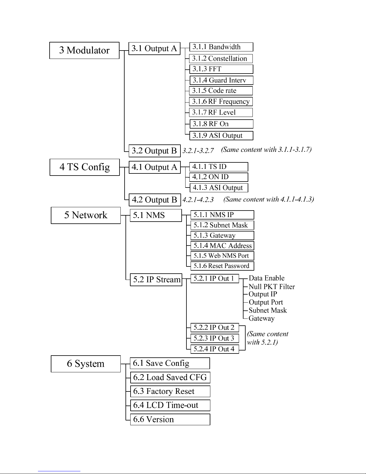
3.1 3.1 LCD Menu Structure
8
9
3.1 Initial Status
After powering on the device,it will take a few seconds to initialize the system It shows as below:
zDVB-T: to indicate the modulation standard of this device.
zA/B: to indicate the 2 carrier outputs
zXXX.XX MHz: to indicate the current output frequency (Range: 30~999MHz) of the 2 carriers
output, which shows in turn.
zP1: Program 1; P2: Program 2; P3: Program 3; P4: Program 4
zX.XX Mbps: to indicate the encoding bit rate of each encoding board respectively.
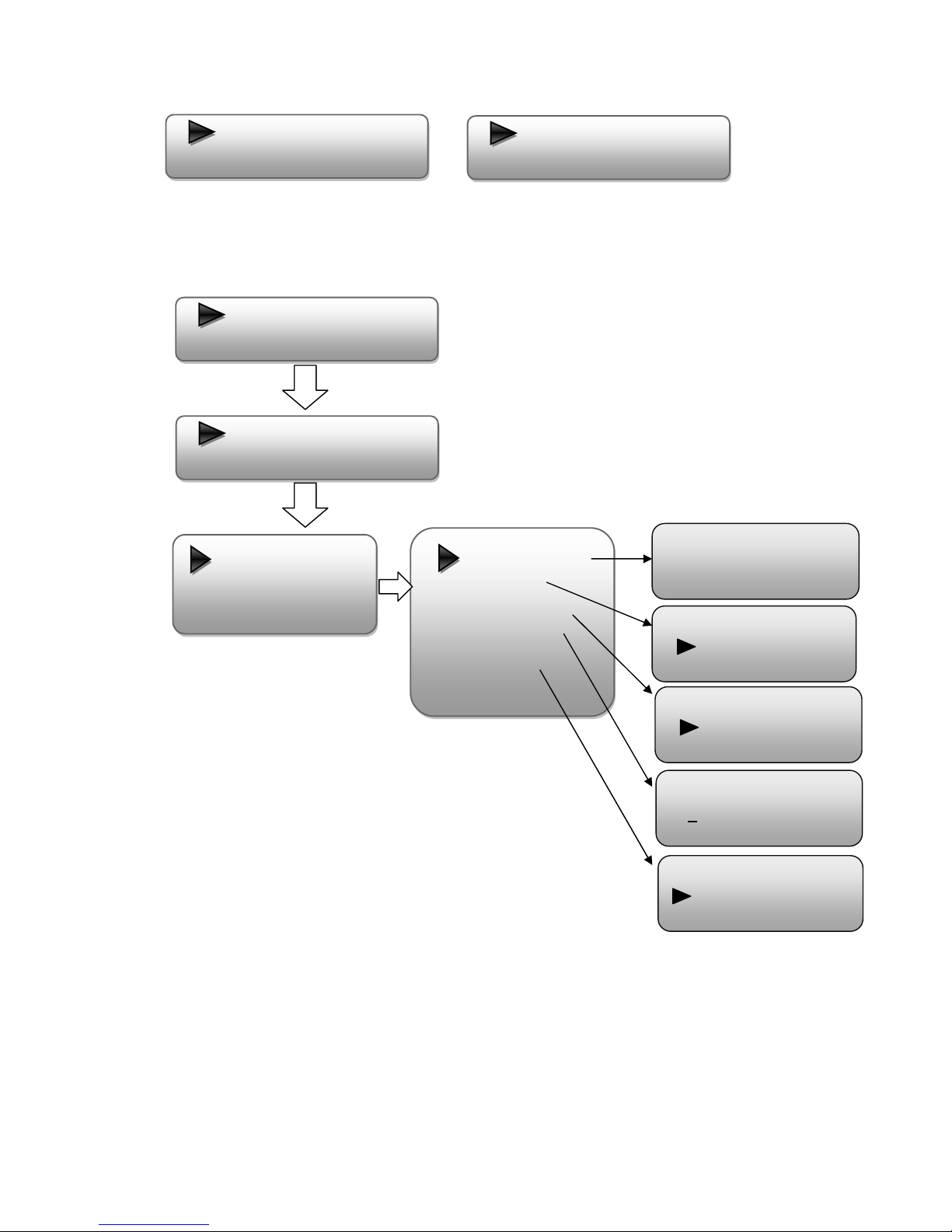
3.2 General setting for Main Menu
By pressing “Lock” key on the front panel, user can enter the main menu. The LCD will display the
following pages:
User can press UP/DOWN buttons to specify menu item, and then press ENTER to enter the
submenus as below:
1) Status
Press Enter to enter “Status” and it displays the working time duration of the device. It times upon
power on
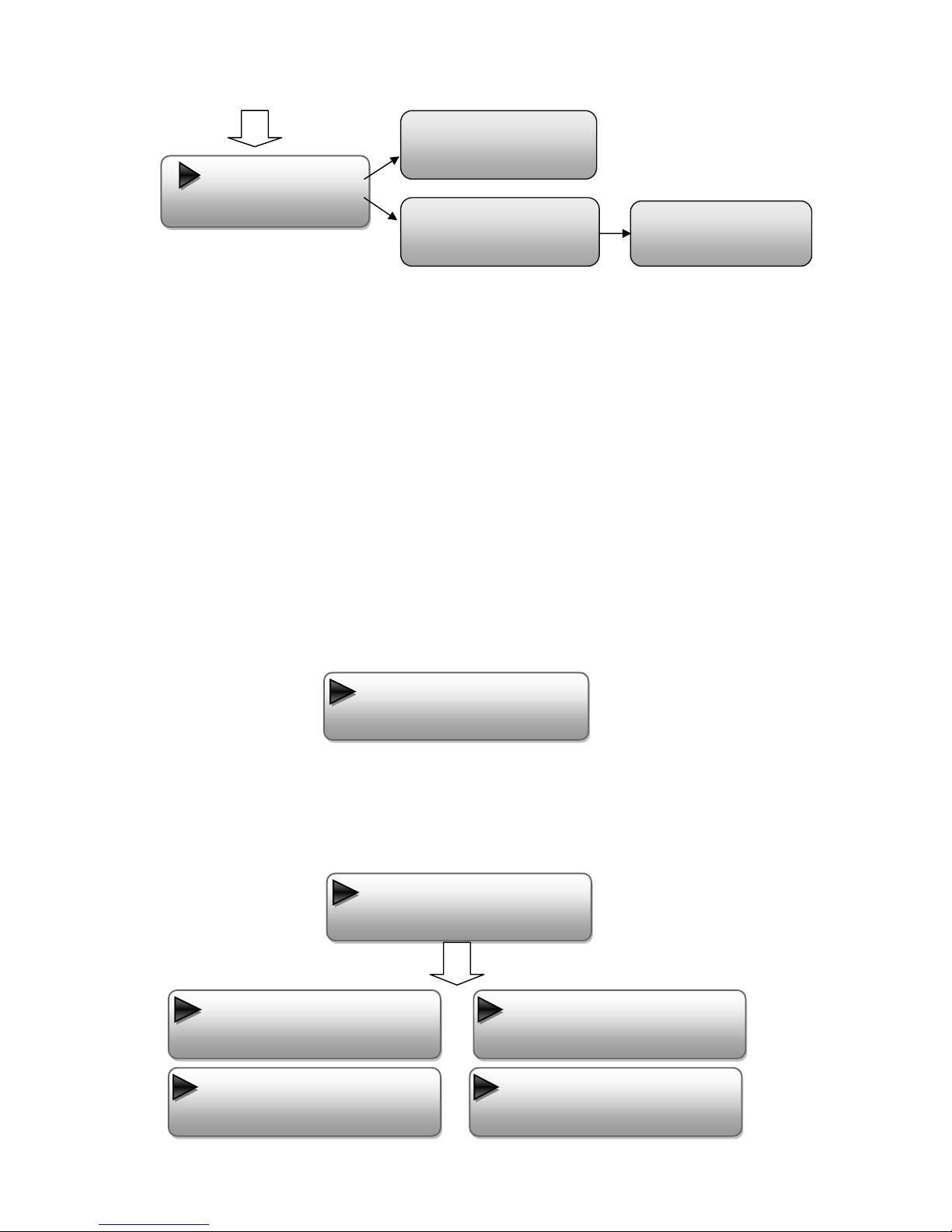
2) Input Sets
Under this submenu, the LCD will show “2.1 Input 1”, “2.2 Input 2” and “2.3 Input 3”.
Startup…StartOK…DVB‐TAXXX.00MHz
P1X.XXMbpsP2X.XXMbps
1Status
2InputSets
3Modulator
4TSConfig
5Network
6System
1.1UptimeUptime
2Days‐10:30:20
10
“2.1 Input 1” and “2.2 Input 2” respectively represent the two encoding boards and there are two
programs under each input. User could enter each program to set the interface as per the signal source
and set the related video & audio parameters.
“Interface”: Connect the signal source to the corresponding input channel and select the interface
from the options provided in the submenu (YPbPr, CVBS and HDMI optional). Press Enter key to
confirm and the system will automatically search the signal source.
“Video Format”: the encoding module supports both MPEG2 and MPEG4 AVC/H.264 formats.
Move the triangle mark with LEFT/RIGHT keys to specify the intended format and press ENTER to
2.1Input1
2.2Input2
2.3Input3
2.1Input1
2.1.1Program1
2.1.2Program2
Videoinstatus
Interface
VideoFormat
VideoBitrate
LowDelay
LowDelay
Normal
Interface
YPbPr
VideoBitRate
08.000Mbps
VideoFormat
MPEG‐2
Video
Audio
ProgramInfo
Videoinstatus
Locked

11
confirm.
“Video Bit Rate”: Move the underline with LEFT/RIGHT keys and modify the value of frequency
(1-19Mbps) with UP/DOWN keys, and press ENTER key to save the settings.
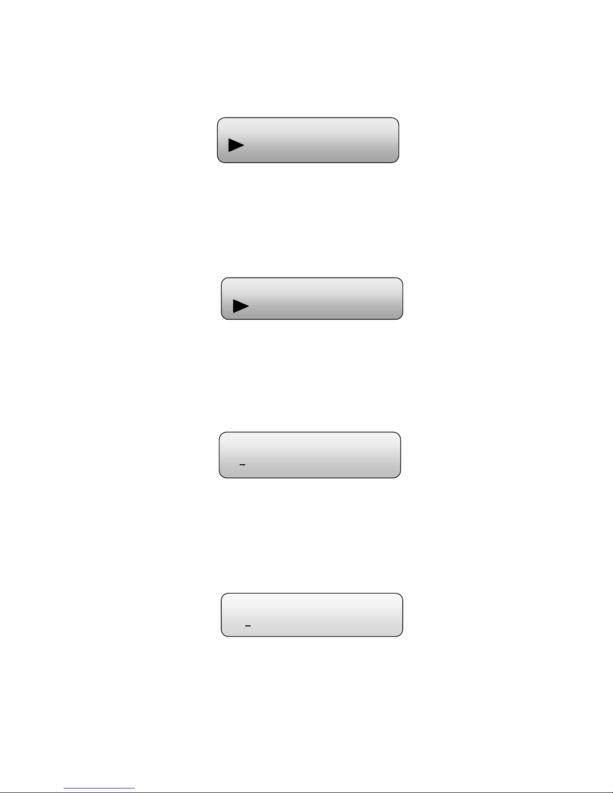
“Low Delay”: Normal: not to enable the low delay mode.
NOTE: The different combination of Video Format, Video Bit-rate, Low Delay Mode and
the Resolution of signal source will have an impact on the time latency on receiving side.
Please refer to the Chapter 6 attached for detailed information.
“Audio Format”: MPEG-1 Layer 2, MPEG-2 AAC, MPEG-4 AAC, AC3, AC3 Passthrough
optional.
“Audio Bitrate”:64-320Kbps optional.
“Audio Gain”: 000% to 400% adjustable.
“2.3 Input 3” represents the ASI input. User could parse and select program(s) to mux out.
2.3Input3
ProgramOutput
ProgramName
ServiceProvider
ProgramID
PMTPID
PCRPID
VideoPID
AudioPID
Video
Audio
ProgramInfo
Audio Format
►MPEG-2 AAC
Audio Bitrate
►128Kbps
Video
Audio
ProgramInfo
AudioFormat
AudioBitrate
AudioGain
Audio Gain
000%
12
“Parse Program” is for checking the quantity of input programs from the corresponding Tuner
input.
“Mux Program” is for selecting programs from the ASI IN to output via corresponding carrier output
(A, B optional). Move the triangle mark to specify the program and press RIGHT/LEFT keys to shift
the mark between “√” and “X”. (“√”: to output the corresponding program; “X”: not to output the
corresponding program)
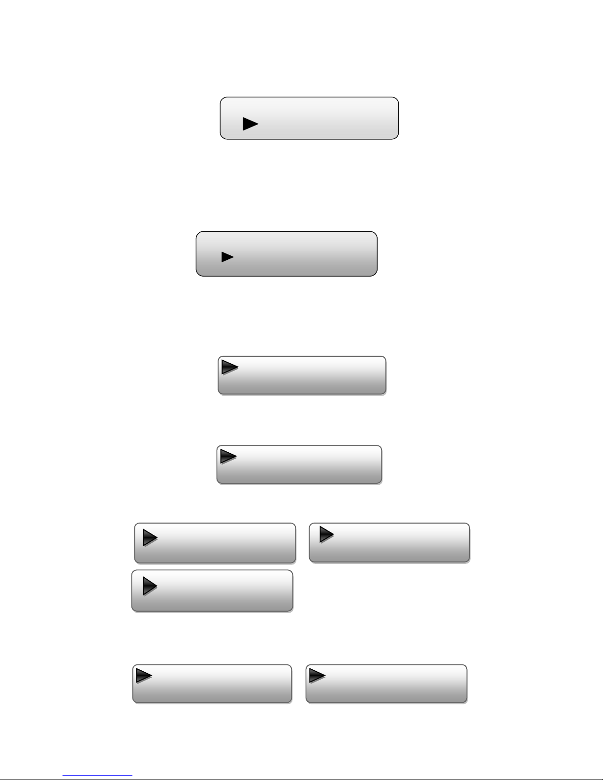
3) Modulator Setting
When entering “Modulator” submenu, user can configure the modulating parameters for the 2
carrier output separately:
As the EPS-HAV1004R (DVB-T Modulating) is with 2 carrier outputs, “3.1”-“3.2” represent
the “Carrier A” and “Carrier B” respectively. User can enter “3.1”/“3.2” to set the corresponding
modulating parameters. Submenus (taking “3.1” as an example) are as below:
►1GXTV√
2SZTVX
ParseProgram
Get3programs
2.3.1ParseProgram
2.3.2MuxProgram
►OutputAMux
OutputBMux
3.1OutputA
3.2OutputB
3.1OutputA
3.1.1Bandwidth
3.1.2Constellation
3.1.3FFT
3.1.4GuardInterval
3.1.5CodeRate
3.1.6RFFrequency
3.1.7RFoutlevel
3.1.8RFOn

13
¾Bandwidth
There are three possible options provided for selecting bandwidth: 6M, 7M, and 8M. When the
display shows them, user just need swift LEFT and RIGHT key to choose and repressing
ENTER to confirm.
¾Constellation
Four different constellations QPSK, 16QAM and 64QAM will be shown on the LCD window.
User can set constellation type with the same method mentioned above.
¾FFT
When user enters FFT (Transmission Mode), the LCD would show the current working
mode. User can move LEFT/RIGHT keys to select and press ENTER key to confirm. 2K
and 8K are the options:
2K: When the device works as current mode, the number of current carrier is 2048
8K: When the device works as current mode, the number of current carrier is 8192
¾Guard Interval
In communications, guard intervals are used to ensure that distant transmissions do not interfere
with each other. These transmissions may belong to different users (as in TDMA) or same user
(as in OFDM). The purpose of the guard interval is to introduce immunity to propagation delays,
echoes and reflections, to which digital data is normally very sensitive. There are four possible
Bandwidth
6M7M8M
Constellation
QPSK16QAM64QAM
TransmissionMode
2K8K
3.1.9ASIOutput
14
options provided to be selected. They are 1/4, 1/8, 1/16, 1/32. User can shift the LEFT/RIGHT
keys to select and press ENTER to confirm.
¾Code Rate
The code rate includes 1/2, 2/3, 3/4, 5/6, and 7/8. After entering this submenu, the LCD
display would show them, users just need press LEFT and RIGHT buttons to choose and press
ENTER button to confirm.
¾RF Frequency
The RF output frequency range is from 30 to 960MHz with 1K stepping. After entering
the RF frequency setting submenu, users the can press LEFT, RIGHT, UP, and DOWN
buttons to adjust the frequency and confirm by press ENTER button.
¾RF Out Level
The RF attenuation range is from -30~-10dbm (77~97dbµV) with 0.1db step. After
entering this setting submenu, user can shift UP/DOWN/LEFT/RIGHT key to set the
output level and press ENTER to confirm.
¾RF On
This interface is to decide whether to enable the RF (carrier A) output or not.
OFF: to disable programs to output through carrier A.
GuardInterval
1/81/161/32
RFFrequency
750.000MHz
RFOutLevel
‐10.0dbm
CodeRate
1/22/33/45/6
15
ON: to enable programs to output through carrier A.
¾ASI Output
EPS-HAV1004R encoder & modulator (DVB-T Modulating) is with two carrier output A, B.
Output A: the ASI output programs are same as carrier output A.
Output B: the ASI output programs are same as carrier output B.
4) TS Config
Enter each menu to configure the TS ID, Original Network ID and choose whether to output the
carrier programs through ASI.
5) Network
Network contains “5.1 NMS” and “5.2 IP Stream”.
“5.1 NMS” is for setting the network parameters for the connection between the device and PC.
“IP Stream” is for configuring the 4 SPTS output respectively.
4.1OutputA
4.2OutputB
5.1.5WebNMSPort
5.1.6ResetPassword
5.1.3Gateway
5.1.4MACAddress
5.1.1NMSIP
5.1.2SubnetMask
5.1NMS
5.2IPStream
5.2.1IPout1
5.2.2IPout2
5.2.3IPout3
5.2.4 IPout4
RFOn
OffOn
ASIOutput
OutputAOutputB

16
6) System
It contains 5 submenus where users can save/load configurations.
DataEnable
NullPKTFilter
OutputIP
OutputPort
ServiceIP
SubnetMask
Gateway
6.1SaveConfig
6.2LoadSavedCFG
6.3FactoryReset
6.4 LCDtime‐out
6.5Version

17
Chapter4WEBNMSoperation
User not only can use front buttons for setting configuration, but also can control and set the
configuration in computer by connecting the device to web NMS Port. User should ensure that the
computer’s IP address is different from the EPS-HAV1004R ’s IP address; otherwise, it would cause
IP conflict.
4.1 login
The default IP of this device is 192.168.0.136. We can modify the IP through the front panel.
Connect the pc and the device with net cable, and use ping command to confirm they are on the
same network segment.
I.G. the PC IP address is 192.168.99.252, we then change the device IP to 192.168.99.xxx (xxx can
be 0 to 255 except 252 to avoid IP conflict).
Use web browser to connect the device with PC by inputting the Encoder & Modulator’s IP address
in the browser’s address bar and press Enter.
It will display the Login interface as Figure-1. Input the Username and Password (Both the default
Username and Password are “admin”.) and then click “LOGIN” to start the device setting.
Figure‐1

18
4.2 Operation
Welcome
When we confirm the login, it displays the WELCOME interface as Figure-2.
Figure-2
Input 1
From the menu on left side of the webpage, clicking “Input 1”, it displays the information of the
programs from the 1st encoding board as Figure-3.
Usercanclickanyitem
heretoenterthe
correspondinginterface
tocheckinformationor
settheparameters.
Devicestandard
andname
Itdisplaysthe
signalsource
interfaceasper
yousetin“Input
1/2”interface
anddisplays
real‐time
encodingbitrate
ofcorresponding
Table of contents


