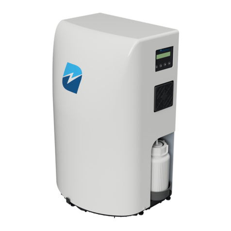
Voltea DiEntry User manual

Step by Step Alarm Troubleshooting

2 | P a g e
The installation, service and maintenance of this equipment should be rendered by a qualified and
trained technician. This troubleshooting guide is written specifically for these individuals and is
intended for their use. Untrained individuals who use this guide assume the risk of any resulting
property damage and personal injury.
WARNING!
Electrical shock hazard: The electrical cabinet
may not be opened when the system is
connected to an electrical power supply, unless
advised.
WARNING!
If incorrectly installed, operated or maintained,
this product can cause severe injury. Those
who install, operate or maintain this product
should be trained in its proper use, warned of
its dangers, and should read the entire reseller
manual before attempting to install, operate,
troubleshoot or maintain this product.
CAUTION!
This product is not to be used by children or
persons with reduced physical, sensory or
mental capabilities, or lack of experience or
knowledge, unless they have been given
supervision or instruction.
CAUTION!
If the power cord from the transformer to the
unit looks or becomes damaged, the cord and
transformer should be replaced by a Voltea
service engineer or similarly qualified person to
avoid hazard.
All rights reserved. No part of this publication may be reproduced, stored in a database or retrieval system, published in any form or in any
way, electronically, mechanically, by print, photo print, microfilm or any other means without prior written permission from the
manufacturer. All Voltea trademarks and logos are owned by Voltea B.V. All other brand or product names are trademarks or registered
marks of their respective owners. Because we are continuously improving our products and services, Voltea reserves the right to change
specifications without prior notice. Voltea is an equal opportunity employer. DiUse Troubleshooting Guide: Copyright © 2018
EUROPEAN OFFICE
Wasbeekerlaan 24
2171 AE Sassenheim, Netherlands
+31(0)252.200.100
US OFFICE
1920 Hutton Court #200
Farmers Branch, TX 75234
+1(469)620.0133

3 | P a g e
Contents
1. General safety precautions..............................................................................................................4
2. DiEntry screen navigation chart ......................................................................................................4
3. Bypass ..............................................................................................................................................5
4. Alarms ..............................................................................................................................................5
4.1 LOW PURIFY (1h)............................................................................................................................6
4.2 LOW WASTE (2h)..........................................................................................................................13
4.3 BYPASS ALARM (4h) .....................................................................................................................20
4.4 CAB. TEMP (8h) ............................................................................................................................20
4.5 LEAKAGE (10h) .............................................................................................................................21
4.6 CIP L.LEVEL (40h)..........................................................................................................................21
4.7 PAE alarms ...................................................................................................................................22
4.8 ZERO EC ERR. (40000h) ................................................................................................................22
4.9 TEMP. ERR (80000h) ....................................................................................................................25

4 | P a g e
1. General safety precautions
Observe the following general safety precautions:
•Always replace damaged or defective parts before putting the system into use again.
•Do not make modification on the system without prior approval of the manufacturer.
•Do not open the door of the electrical cabinet when the system is powered on, unless advised
to do so.
•If chemicals are supplied, the attached safety procedures should be observed.
2. DiEntry screen navigation chart
The flow chart gives an overview of the DiEntry functions and parameters that can be controlled
through the LCD.

5 | P a g e
3. Bypass
DiEntry is equipped with an automatic bypass. For more information on the bypass logic please refer
to the DiEntry Reseller manual (Chapter 7.4 Bypass).
The bypass valve is normally open. Close the bypass valve before troubleshooting.
To close the Bypass, remove the white/blue cable (blue cable shoe) from the valve connection and
connect the red cable (blue cable shoe).
NOTE: Return the Bypass valve to its original state (white/blue cable connected) after troubleshooting.
4. Alarms
If an alarm occurs, the alarm symbol ‘’!’’ will appear on the process step screen.
OPERATION
100 uS/cm !
If an alarm occurs and the unit is equipped with a SIM card, an automated SMS will be sent with the
alarm code (for more information on alarms please refer to DiEntry reseller manual). This automated
procedure is valid for all the alarms except the PAE COMM ERR., I2C and Temp. ERR. alarms, these are
self-resolved and do not require any action or special troubleshooting, for this reason no SMS
response is trigged by the unit. The user can be notified for these alarms only via the daily summary
report e-mail. If a PAE alarm is persistent for a time period of one week please conduct Voltea.
The following chapters display a step by step troubleshooting procedure for every possible alarm. If
the issue is not identified during the first troubleshooting event, please continue to the next event
until the issue is identified. If all the steps are followed and the root cause of the alarm is not identified
please contact Voltea or an authorized reseller.
Bypass valve
Bypass line

6 | P a g e
4.1 LOW PURIFY (1h)
The LOW PURIFY alarm is triggered when the average flow during the purification step is smaller than
the Low Flo P.Alrm setpoint. The unit goes to IDLE after the pure step is completed, to restart the unit
and resolve the alarm press Enter.
To troubleshoot the unit when this alarm occurs please do the following:
A. Flow
oEnsure DiEntry is supplied with water.
oRestart normal operation by pressing Enter.
oObserve the flow during pure step through the LCD screen.
▪If the flow is 0 l/m during the pure step, please go to troubleshooting event
B.
▪If the flow is not 0 l/m but the alarm is triggered at the end of the pure step,
please go to troubleshooting event F.
oIf the alarm is not triggered again at the end of the pure step:
▪Alarm was triggered due to a feed water cut off, unit is operating as designed.
B. Main Inlet Valve (MIV) and Pure Outlet Valve (POV)
oEmpty the storage tank via the application or the drain.
oUsing the LCD screen navigate to the Relay Test screen.

7 | P a g e
oOpen the POV first and then the MIV.
oObserve the flow sensor on the water side.
▪If the flow sensor is spinning, water if flowing. If the spinning is not visible use
a flashlight on the bottom of the sensor while water is flowing.
C. Flow chip
Tools: Flathead screwdriver.
oOpen the electrical cabinet.
oLocate the flow chip.
oObserve the LED indication on the chip.
▪LED on the bottom left corner should be blinking green during normal
operation. If this LED is blue, please replace the flow chip.
▪LED on the top right corner should be rotating. If the LED is not rotating during
normal operation, please replace the flow chip.
Flow sensor
Flow Chip
Rotating blue LED
Blinking green LED

8 | P a g e
D. Flow sensor
oOpen the electrical cabinet and check the flow sensor connections on the PCB. The
wires from top to bottom should be : green - white - brown.
E. Flow chip K factor
Tools: Flathead screwdriver, laptop, USB to micro-USB cable, Docklight software.
oConnect the unit via the Docklight software, for more information on how to connect
your laptop to the unit please refer to DiEntry Reseller manual (Chapter 9.2
Connecting to laptop and utilizing Docklight).
oExecute the following command by pressing the arrow.
The unit should respond with the K factor
If the K factor is not registered the response below will appear:
Please replace the flow chip.
F. Inlet pressure
Tools: Manometer with 3/8’’ connections.
Check if the inlet pressure is enough for DiEntry optimal operation ( >3 bar –43.5 psi). In order
to check the inlet pressure, you will need to attach an external manometer to the feed line
just before the DiEntry inlet.
oClose the water supply to the DiEntry
oFlush the unit with the feed supply closed using the automated function (Flush
Module) for 5 seconds to depressurize the system.
Flow sensor wiring

9 | P a g e
oDisconnect the IN line.
oConnect the manometer to the IN line.
oReconnect the IN line.
oOpen the feed water supply and restart normal operation.
oObserve the manometer during the Pure step. Pressure indicated by the manometer
should always be above 3 bar (43.5 psi).
oIf the inlet pressure is not meeting the required 3 bar (43.5 psi), adjust if possible or
conduct Voltea.
G. System pump
oStart normal operation.
oObserve the system pump, confirm operation by checking if the pump vibrates during
the purification step.
NOTE: If the feed pressure is enough for the unit to reach the P. Flow Target setpoint
the pump will remain inactive (no vibration).

10 | P a g e
H. Low Flow P.Alrm setpoint and the pure line flow restrictor.
Tools: Adjustable wrench, a hex key (to push the flow restrictor out of the manifold).
oNavigate to the Setpoint screen and check the Low Flo P.Alrm setpoint. Compare it
with Voltea’s recommendation for your application, adjust if needed.
oClose the water supply to the DiEntry
oFlush the unit with the feed water supply closed using the automated function (Flush
module) for 5 seconds to depressurize the system (skip this step if no water was
introduced to the unit after step F).
oCheck the color of the pure line flow restrictor. Confirm that the flow restrictor is in
line with Voltea’s recommendation for your application, replace if needed.
▪Remove the module manifold.
▪Remove the pure line connection and check the flow restrictor color.
Module manifold

11 | P a g e
oThe flow restrictor color corresponds to a flow as described in the table below. Divide
the Low flow restrictor nominal value by 2. The result should be equal to the Low Flo
P.Alrm setpoint (±0.1 l/m). In case of deviations please contact Voltea.
Color
Flow (l/m)
Flow(gpm)
olive
2.0
0.52
brown
3.0
0.79
grey
4.0
1.05
yellow
5.0
1.32
black
6.0
1.58
green
7.0
1.84
natural
8.0
2.11
orange
9.0
2.37
light blue
10.0
2.64
red
12.0
3.17
pink
14.0
3.69
lime
15.0
3.96
blue
16.0
4.22
I. Pure line flow restrictor free from blockage:
Tools: Tools: Adjustable wrench, a hex key (to push the flow restrictor out of the manifold).
oClose the water supply to the DiEntry
oFlush the unit with the feed water supply closed using the automated function (Flush
Module) for 5 seconds to depressurize the system (skip this step if no water was
introduced to the unit after step F).

12 | P a g e
oRemove the module manifold.
oCheck the pure line flow restrictor for blockage
▪Unscrew the middle and pure ½’’ inch connections from the manifold
▪Push the pure line flow restrictor out using the central connection opening.
Module manifold

13 | P a g e
▪If the flow restrictor is scaled or blocked, replace it with a new one of the
same color.
J. CIP cleaning:
oNavigate to the setpoints screen.
oChange the CIP cycle count to the minimum value (5)
oOperate the unit for 5 cycles.
▪If the Low flow alarm is triggered, acknowledge the alarm and restart by
pressing ENTER.
oAfter 5 completed pure steps, a CIP cleaning will follow.
▪The CIP cleaning duration is around 35 minutes.
oCheck for improvement after the CIP cleaning is finished.
oNavigate to the setpoints screen.
oChange the CIP cycle count to the original value (default value is 432).
4.2 LOW WASTE (2h)
The LOW WASTE alarm is triggered when the average flow during the waste step is smaller than the
Low Flo W.Alrm setpoint. Unit goes to IDLE after the waste step is completed, to restart the unit and
resolve the alarm press Enter.
To troubleshoot the unit when this alarm occurs please do the following:
A. Ensure the waste line is free from scaling and connected to an open/atmospheric drain.
B. Ensure DiEntry is supplied with water.
oRestart normal operation by pressing Enter.
oObserve the flow during the waste step through the LCD screen.
oIf the flow is 0 l/m during the waste step, please go to troubleshooting event C.
oIf the flow is not 0 l/m but the alarm is triggered at the end of the waste step, please
go to troubleshooting event G.
oIf the alarm is not triggered again at the end of the waste step:
▪The alarm was triggered due to feed water cut off, unit is operating as
designed.
C. Main Inlet Valve (MIV) and Waste Outlet Valve(WOV)
oUsing the LCD screen navigate to the Relay Test screen.

14 | P a g e
oOpen the WOV first and then the MIV.
oObserve the flow sensor on the water side.
▪If the flow sensor is spinning the water is flowing. If flow is not visible use a
flashlight on the bottom of the sensor while water is flowing.
D. Flow chip
oOpen the electrical cabinet.
oLocate the flow chip.
Flow sensor

15 | P a g e
▪
oObserve the LEDs on the chip
▪LED on the bottom left corner should be blinking green during normal
operation. If this LED is blue, please replace the flow chip.
▪LED on the bottom top right should be rotating. If the LED is not rotating during
normal operation, please replace the flow chip.
E. Flow sensor
oOpen the electrical cabinet and check the flow sensor connections on the PCB. The
wires from the top to bottom should be : green –white –brown.
Flow sensor wiring

16 | P a g e
F. Flow Chip K factor
Tools: flathead screwdriver, laptop, USB to micro-USB cable, Docklight software.
oConnect the unit via the Docklight software, for more information on how to connect
your laptop to the unit please refer to DiEntry Reseller manual (Chapter 9.2 Connecting
to laptop and utilizing Docklight).
oExecute the following command by pressing the arrow.
The unit should respond with the K factor:
If the K factor is not registered the response below will appear:
Please replace the flow chip.
G. Inlet pressure
Tools: Manometer with 3/8’’ connections.
Check if the inlet pressure is enough for DiEntry optimal operation (>3 bar –43.5 psi). In order
to check the inlet pressure, you will need to attach an external manometer to the feed line just
before the DiEntry inlet.
oClose the water supply to the DiEntry
oFlush the unit with the feed supply closed using the automated function (Flush
Module) for 5 seconds to depressurize the system.
oDisconnect the IN line.
oConnect the manometer to the IN line.
oReconnect the IN line.

17 | P a g e
oOpen the feed line and restart normal operation.
oObserve the manometer during waste step. Pressure indicated by the manometer
should always be above 3 bar –43.5 psi.
oIf the inlet pressure is not meeting the required 3 bar –43.5 psi, adjust if possible or
conduct Voltea.
H. Low Flo W.Alrm setpoint and the waste line flow restrictor.
Tools: Adjustable wrench, hex key (to remove the flow restrictor from the manifold).
oNavigate to the setpoints screen and check the Low Flo W.Alrm setpoint. Compare it
with Voltea’s suggestion for your application, adjust if needed.
oClose the water supply to the DiEntry.
oFlush the unit with the feed supply closed using the automated function (Flush
Module) for 5 seconds to depressurize the system.
oCheck the color of the waste line flow restrictor. Confirm that the flow restrictor is in
line with Voltea’s suggestion for your application, replace if needed.
▪Remove the module manifold.

18 | P a g e
▪Remove the waste line connection and check the flow restrictor color.
oThe flow restrictor color corresponds to a flow as described in the table below. Divide
the low flow restrictor value by 2. The result should be equal to the Low Flo W.Alrm
setpoint (±0.1 l/m). In case of deviations please contact Voltea.
Color
Flow (l/m)
Flow(gpm)
Olive
2.0
0.52
Brown
3.0
0.79
Grey
4.0
1.05
Yellow
5.0
1.32
Black
6.0
1.58
Green
7.0
1.84
Natural
8.0
2.11
Orange
9.0
2.37
Light Blue
10.0
2.64
Red
12.0
3.17
Pink
14.0
3.69
Lime
15.0
3.96
Blue
16.0
4.22
Module manifold

19 | P a g e
I. Waste line flow restrictor free from blockage.
Tools: Adjustable wrench, hex key (to remove the flow restrictor from the manifold).
oClose the water supply to the DiEntry
oFlush the unit with the feed water supply closed using the automated function (Flush
module) for 5 seconds to depressurize the system (skip this step if no water was
introduced to the unit after step F).
oRemove the module manifold.
oCheck the waste line flow restrictor for blockage.
▪Unscrew the middle and waste ½’’ connections from the manifold.
Module manifold

20 | P a g e
▪Push the waste line flow restrictor out using the central connection opening.
▪If the flow restrictor looks scaled or blocked. Replace it with a new one of the
same color.
J. CIP cleaning
oNavigate to the setpoints screen.
oChange the CIP cycle count to the minimum value (5)
oOperate the unit for 5 cycles.
▪If the Low flow alarm is triggered, acknowledge the alarm and restart by
pressing ENTER .
oAfter 5 compete cycles, a CIP cleaning will follow.
▪The CIP cleaning duration is around 35 minutes.
oCheck for improvement after the CIP cleaning is finished.
oNavigate to the setpoint screen.
oChange the CIP cycle count to the original value (default value is 432).
4.3 BYPASS ALARM (4h)
The Bypass alarm is triggered when the pure line pressure has dropped below the setpoint of the
bypass pressure switch (2 bar - 29 psi) for more than 900 seconds. The alarm will resolve automatically
when the pressure increases above 2 bar - 29 psi.
Since the CIP cycle is around 35 minutes the Bypass alarm can be triggered while the unit is in CIP and
the pressure in the pure line reduces below 2 bar.
If the Bypass alarm triggers repeatedly and is not linked with the CIP cycle, it is possible that the unit
cannot cope with the water demand. Please contact Voltea.
4.4 CAB. TEMP (8h)
Temperature inside the electrical cabinet greater than 40 °C - 104 °F. System jumps to wait until the
temperature inside the electrical cabinet decreases to less than 40 °C - 104 °F. The minimum time
the unit stays in wait is 10 minutes.
A. Ensure the ambient temperature is < 40 °C - 104 °F.
B. Ensure proper ventilation for the DiUse electrical cabinet.
oRemove any object that would cause poor ventilation.
C. Open the electrical cabinet and check the fan filter. Replace if needed.
Other manuals for DiEntry
1
Table of contents
Other Voltea Water Filtration System manuals
Popular Water Filtration System manuals by other brands

Grohe
Grohe 40 438 manual

Culligan
Culligan Drinking Water System owner's guide

HYDAC FILTER SYSTEMS
HYDAC FILTER SYSTEMS OF5 S Series Installation and maintenance instructions

Grunbeck
Grunbeck pureliQ:K Operation manual

Bestway
Bestway 58500 owner's manual

3P Technik
3P Technik Twin Filter operating instructions

Life Ionizers
Life Ionizers M11 user manual

Brita
Brita Active manual

Watts Premier
Watts Premier WP-2 LCV Installation, operation and maintenance manual

HYDAC International
HYDAC International RFD Series Service and Parts

3P Technik
3P Technik 3P Rustico instruction sheet

Emerald
Emerald Home 4 Passport and operaton manual