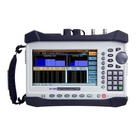
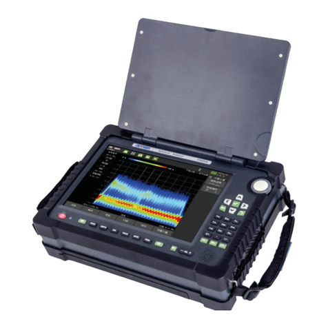
Deviser S7200 User manual

S7200
TV Signal Spectrum Analyzer
User Guide

S7200 TV Signal Analyze
r
2
Table of Contents
PARTI:S7200BASICS5
SafetyPrecautions6
MaintenanceandSafetyConsiderations7
CalibratingtheMeter7
OtherSafetyandMaintenanceTips7
Warranty9
Chapter1:GeneralInformation10
1‐1AbouttheS7200TVSignalSpectrumAnalyzer10
1‐2AccessoriesandMeasurementOptions11
1‐3TechnicalSupport&Service11
1‐4AnnualServiceVe r i f i c a t i o n 11
1‐5ElectrostaticDischargeCaution12
1‐6BatteryCare12
GlossaryofAcronyms14
Chapter2:InstrumentOverview16
2‐1UnpackingtheS7200Instrument16
2‐2PoweringOntheS720016
2‐3FrontPanelOverview17
2‐4TopandSidePanelOverview18
2‐5ControlOverview19
2‐6MeasurementMainMenu20
2‐7SetUpYourChannelPlanFirst21
2‐8MeasurementModeSelection22
2‐9AbouttheSoftCarryingCase22
PARTII:SETTINGSANDMEASUREMENTS23
Chapter3:ChannelPlans24
3‐1TVChannelPlans24
3‐2SatelliteChannelPlans29
Chapter4:AnalogTVMeasurements32
4‐1ChannelMeasurement32
4‐2AnalogFM33
4‐3HUMModulation34
4‐4ChannelScan35
4‐5PassiveSweep36
4‐6TiltMeasurement37
4‐7DepthofModulation(DOM)38
4‐8FMDemodulation38
4‐9Auto39

3
S7200 TV Signal Analyze
r
Chapter5:AnalogNon‐LinearDistortionTests40
5‐1CNR40
5‐2
CTB/CSO
42
Chapter6:DigitalSignalMeasurements43
6‐1
DVB‐CMeasurement
44
6‐2DigitalHUM45
6‐3
ConstellationDiagram
46
6‐4ErrorVectorSpectrum(EVS)Function47
6‐5ATSC(8VSB)Measurement48
6‐6DVB‐C2Measurement50
6‐7DVB‐T/HMeasurement51
6‐8DVB‐T2Measurement54
6‐9ISDB‐TbMeasurement57
6‐10DVB‐S/S2Measurement58
6‐11AntennaEdit59
6‐12TransportStreamAnalysis62
6‐13IPTVMeasurement79
6‐14OpticalPowerMeasurementandOpticalReceiver80
6‐15DownstreamSpectrumAnalysis84
6‐16WiFiAnalysis92
6‐17DTMBMeasurement93
6‐18DAB/DAB+Measurement95
PARTIII:BACKGROUNDANDCONCEPTS96
Chapter7:AnalogTVStandards&ColorSystems97
Chapter8:AnalogTVBasebandSignals100
8‐1UnderstandingCompositeVideoSignal100
8‐2PrinciplesofInterlacedScanning102
8‐3PrinciplesofGatedMeasurements103
Chapter9:SatellitesandTransponders109
9‐1Sub‐Satellites109
9‐2PolarizationandLNB110
9‐3SaTCROverview112
Chapter10:ResolutionandVideoBandwidth113
10‐1ResolutionBandwidthfilter(RBW)113
10‐2VideoBandwidthfilter(VBW)113
Chapter11:DetectorMode114
Chapter12:InternationalCATVStandards115

S7200 TV Signal Analyze
r
4
PARTIV:SYSTEMFUNCTIONS123
Chapter13:SystemSettings124
13‐1About(SystemInformation)124
13‐2GeneralSettings125
13‐3MeasureSettings128
13‐4ExternalInterfaceSetup132
13‐5AntennaSettings140
13‐6UpdatingSystemFirmware142
Chapter14:FileManagement143
14‐1FileOperations143
14‐2ImportingandExportingData144
Chapter15:SavingData145
15‐1Screenshots145
15‐2MeasurementData145
SPECIFICATIONS146

5
S7200 TV Signal Analyze
r
Part I
S7200 Basics

Part I: S7200 Basics
6
Safety Precautions
The following are general safety precautions that are not necessarily related to any specific part or
procedure, and do not necessarily appear elsewhere in this publication. These precautions must be
thoroughly understood, and they apply to all phases of operation and maintenance. Deviser Instruments,
Inc. assumes no liability for the operator’s failure to comply with these precautions
WARNING
Plug Compatibility
Before connecting to AC power, please insure the adaptor plug fits the wall configuration on
one end, and the power supply plug configuration on the other end. Incorrect configuration
may damage the power supply.
WARNING
Shock Hazard
To avoid the possibility of severe injury or death, observe the following precautions when
using the S7200 TV Signal Spectrum Analyzer:
Do not remove the system covers, and do not perform electrical tests if there are
signs of shipping damage to the outer enclosure.
When connecting test cables to a line, do not touch the cable’s metal contact
points, or allow the cable leads to touch each other.
Use only the supplied power cords and connect only to a properly grounded wall
outlet. Do not use extension cords that do not have a protective ground conductor.
WARNING
Explosion Hazard
Do not operate the instrument in the presence of flammable gases or fumes.
W ARNING
Do Not Use If Damaged
Do not use this product if it shows visible damage, fails to perform, has been stored in
unfavorable conditions, or has been subject to severe transportation stresses. Secure the
product against any unintended operation and contact a Deviser Instruments, Inc. Factory
Authorized Service Center for assistance.
WARNING
Remove Power
Observe general safety precautions. Do not open the instrument with the power on.
WARNING
Battery Care
Danger of explosion if the battery is incorrectly replaced. It is recommended to replace the
battery only with the same type. Do not dispose of batteries in fire or trash. Batteries must be
recycled or disposed of properly.

Part I: S7200 Basics
7
Maintenance and Safety Considerations
Calibrating the Meter
Any instrument with analog circuitry (including preamplifiers, filters, etc.) may change in performance over
time. Regular calibration will keep your instrument in optimal working condition to support your test, design,
troubleshooting, and manufacturing needs.
It is recommended to calibrate and verify the instrument at least once per year to ensure that it meets the
stated performance specifications.
To avoid damaging the default calibration data stored in device memory, instrument calibration should
only be performed with appropriate equipment by qualified personnel at a Deviser Instruments, Factory-
Authorized Service Center.
Environmental conditions:
Calibration and verification tests should be performed in a laboratory where the ambient temperature and
relative humidity can be controlled.
Warm up:
Allow up to at least 5 minutes’ warm- up before calibrating the instrument. If the unit has been exposed to
or stored in a high-humidity (condensing) environment, allow more time.
For detailed information on calibration procedures, please contact an authorized Deviser distributor.
Other Safety and Maintenance Tips
Please charge and discharge the battery every 3 months to extend battery life. Recharge the battery only
in the instrument; If left unused, a fully charged battery will discharge itself over time.
Never use a damaged or worn-out adapter or battery. During charge, the unit may be warm to the touch
even if it is powered off. To avoid overheating, always disconnect the unit from the AC adapter before
storing it in the carrying case.
CAUTION:
Extreme temperatures will affect the ability of the battery to charge. Allow the battery to return
to room temperature before use or charging. Storing a battery in extreme hot or cold temperatures will
reduce its capacity and lifetime. It is recommended to store batteries at temperatures less than 25°C.
The unit cannot be used in its carrying case for more than 1 hour if the ambient temperature exceeds 35°C.
CAUTION
: Use only the original AC-DC adapter and battery to power the unit. To charge, simply insert the
battery into the unit’s back panel, plug in the AC-DC adapter, and switch the power on if necessary. If the
LED is red, the battery is charging. When fully charged, the LED will turn green. Time required to fully charge
a depleted battery is approximately four hours, but may be longer if the instrument is in use while charging.
CAUTION
: While updating firmware, the unit must remain connected to power and at more than 60%
battery power. If power fails during the updating process, instrument function may be affected.
DANGER
: The S7200 contains an optional VFL (Visual Fault Locator). To avoid eye damage, never look
directly into the VFL output port while the light is on, and wear appropriate eye protection when necessary.

Part I: S7200 Basics
8
Safety Symbols
The following are general definitions of safety symbols used on equipment and in manuals.
Dangerous voltage.
Protective ground.
Frame or chassis ground.
Alternating current.
Direct current.
Alternating or direct current.
Caution! Read the manual.

Part I: S7200 Basics
9
Warranty
This Deviser Instruments, Inc. product is warranted against defects in material and workmanship for a period
of 36 months from the date of shipment. Under warranty, Deviser Instruments, Inc. will, at its option, either
repair or replace products which prove to be defective.
Extended warranty options are available
. Please contact your local Deviser Instruments sales representative
for more information.
For warranty service or repair, this product must be returned to a Deviser Instruments Factory Authorized
Service Center designated. The buyer shall prepay shipping charges to Deviser Instruments Inc. or to the
service center and Deviser Instruments Inc. or the service center shall pay the shipping charges to return the
product to the buyer. However, for products returned to Deviser Instruments Inc. or one of its authorized
service centers outside the warranty period, the buyer is responsible for all shipping charges, duties, and
taxes, both ways.
Deviser Instruments Inc. warrants that software and firmware designated by Deviser Instruments Inc. for use
with an instrument will execute its programming instructions when properly installed on that instrument.
Deviser Instruments Inc. does not warrant that the operation of the instrument or its software or firmware will
be uninterrupted or error-free.
Limitation of Warranty
Unauthorized repair or update, physical damage or improper operational voltage (at the power supply or
RF input) will void this warranty. The main lithium battery is only covered for a period of 12 months.
The foregoing warranty shall not apply to defects resulting from the following:
Improper or inadequate use or maintenance by Buyer
Buyer-supplied software or interfacing
Unauthorized modification or misuse
Operation outside of the environmental specifications for the product.
NO OTHER WARRANTY IS EXPRESSED OR IMPLIED. DEVISER INSTRUMENTS INC SPECIFICALLY DISCLAIMS THE
IMPLIED WARRANTIES OF MERCHANTABILITY AND FITNESS FOR A PARTICULAR PURPOSE.
Updates, if any, may be downloaded from the Deviser web site at http://www.deviserinstruments.com/.

Part I: S7200 Basics
10
Chapter 1: General Information
The
S7200
is a handheld TV Signal Analyzer that integrates multiple measurement applications in a single
instrument, ideal for use by CATV field technicians and HE engineers. These applications provide most of the
measurements required to maintain optimum performance of a CATV network.
The firmware installed on the S7200 is updated on a regular basis. This User Guide documents procedures for
operating the instrument based on the most recent firmware version up to the date listed on the guide.
1-1 About the S7200 TV Signal Spectrum Analyzer
The product of revolutionary advances in TV signal analysis technology, the S7200 includes a host of
features typically found in more expensive instruments and provides outstanding performance for value.
The S7200 enables field engineers to perform in-service measurements and identify interference signals that
are invisible to many field instruments currently available on the RF test equipment market. The high-speed
spectrum analysis tool supports multiple cable, terrestrial, and satellite digital TV standards, including DVB-
C/C2, DVB-S/S2, DVB-T/T2, DTMB, DAB, and ATSC or ISDB-Tb (on select models – see below). It can measure
frequencies of 4 ~ 1220 MHz for cable/terrestrial testing, and 950 ~ 2150 MHz for satellite applications.
The TV analyzer function also supports a wide range of video encoding formats, like MPEG2/4, H.264, H.265,
AVS(+), and VC-1, with HD and SD image decoding (4K, 1080p, 720p, 576i, etc.) With the optional DVB-CI
tool, users can even decode encrypted programs. The S7200 also supports mode 1/E BISS decryption.
Support for analog TV standards includes NTSC, PAL, and SECAM.
As 700 MHz becomes more popular for LTE service, LTE signals effectively occupy the same frequency band
as CATV service. The S7200’s time-domain EVS function allows users to check LTE interference without
interrupting service.
The S7200 can perform TS (transport stream) analysis with the RF and ASI ports; simply record the output to a
SATA SSD or USB device for easy playback. In line with recent strides in optical LNB use, optical power meter
and optical receiver options are available. Other optional features include IPTV, WiFi analysis, and a GPS
dongle for key location measurements.
Each instrument comes with basic TV and spectrum measurement functions for particular standards, based
on the model. Optional functions may be enabled either at the time of purchase, or at a later date as your
test needs evolve. See the following model and option guides.
Model Guide
Models Features
S7200 Standard DVB-C (J.83 Annex A/C), S/S2, T/T2, H, ASI Input & Output
S7200-ATSC DVB-C (J.83 Annex A/B/C) S/S2, T/T2, H, ATSC, ASI Input & Output,
Spectrum Emissions Mask
S7200-ISDB-Tb DVB-C (J.83 Annex A/C) S/S2, T/T2, H, ISDB-Tb; ASI Input & Output

Part I: S7200 Basics
11
1-2 Accessories and Measurement Options
SKU No. Type Description
S7200-000 Accessory S7200 English calibration certification
SFL10-KK Accessory TOKO Type-F(f) to Type-F(f) adapter
S7200-001 Accessory S7200 carrying case
S7200-002 Accessory Toolbox software & operation manual CD
S7200-003 Accessory S7200 quick operation guide (English)
S7200-007 Accessory Car charger
FSP060-DBAE1 Accessory AC/DC adapter
S7200-801 Option DVB-C2 support
S7200-802 Option TR 101 290 Transport Stream analysis (MPEG-TS)
S7200-803 Option IPTV Analysis, 10/100/1000 Mbps
S7200-804*Option DVB-CI Conditional Access Module (CAM) for channel decryption
S7200-805 Option 802.11 b/g/n Wi-Fi Analysis
S7200-201* Option Optical Receiver & Power Meter
KM200032SSD Option Serial AT attachment (SATA) disk
DS2500-704 Option GPS (USB) Dongle
S7200-004 Option English User Guide (hard copy)
AE4000-733 Option Power adapter (EU)
AE4000-734 Option Power adapter (US)
AE4000-735 Option Power adapter (UK)
AE4000-736 Option Power adapter (AUS)
S7200-005 Option 1-year extended warranty
1-3 Technical Support & Service
Deviser Instruments Inc. offers a 24-month warranty, and ongoing support and training services. Customers
are eligible to receive initial on-site training from our technical support engineers in a “train the trainer”
format. Our application engineers can also answer questions and provide ongoing technical support
regarding software or equipment. For special applications, Deviser instruments offers custom software
design at an extremely competitive rate and time-to-market.
Ongoing development and “maintenance engineering” is provided on all products; yearly maintenance
programs are offered to ensure that customers fully benefit from the latest upgrades available. Technical
documents and application guides are released on an ongoing basis.
1-4 Annual Service Verification
Accurate test measurements are critical to your business. Deviser Instruments recommends an annual
calibration and performance verification as a means to keep your instrument in optimal working condition.
Please contact Deviser Instruments for an RMA number and the location of the nearest Authorized Deviser
Instruments service center. Our authorized service centers are skilled and certified in the calibration, service,
repair, and performance verification of our products.
*
This option requires hardware modification at a Deviser-authorized service center.

Part I: S7200 Basics
12
1-5 Electrostatic Discharge Caution
The S7200 TV Signal Spectrum Analyzer, like other high-performance instruments, is susceptible to
electrostatic discharge (ESD) damage. Coaxial cables and antennas often build up a static charge, which
may damage the S7200 input circuitry. S7200 operators must be aware of the potential for ESD damage
and take all necessary precautions.
It is recommended to discharge the static by connecting a short or load device to the cable or antenna
before connecting them to the S7200. It is important to remember that the operator may also carry a static
charge that can cause damage. Following the practices outlined in the above standards will ensure a safe
environment for both personnel and equipment.
When connecting a coaxial cable to the instrument for the first time that day, the center conductor
of the cable and the outer braided shielding layer should be quickly grounded.
During service, ensure that the technician is grounded before removing inner components or pulling
out connecting cables.
Ensure that the instrument is well grounded, so as not to store any static charges.
Electrostatic protection of this instrument is up to standards of 6KV contact and 8KV air-gap.
1-6 BatteryCare
The S7200 can be supplied with power in two different ways: with the built-in battery or with the power
adapter provided.
1-6.1 Battery
The S7200 uses a 7.4V/13Ah lithium battery for autonomous operation. Battery life during continuous use (on
a full charge) is estimated at more than 8 hours. When the voltage falls below 6.9V, the instrument will
display an alert indicating low charge. At 6.7V or less, it will display a second alert and the battery icon will
flicker. At 6.2V or less, following a third alert, the instrument will emit a long audible beep and shut down
automatically. Further use requires that the unit be connected to an external AC or DC power source,
which will also charge the battery. If the unit stays off, it will take about 4 hours to fully recharge. Charging
time will be longer if the unit is in use.
NOTE: Use only Deviser Instruments-approved batteries, adapters, and chargers provided with this
instrument.
WARNING: Low temperatures may cause a temporary reduction of the battery capacity. This will not
damage the battery. High temperatures, however, may cause permanent damage to the battery. See
stated specifications for environmental tolerances. Recommended charging temperature is 10~35°C.
NOTE: It is advisable to replace the battery when operational time falls below 50% of original capacity.

Part I: S7200 Basics
13
1-6.2 Charging the Unit
Please follow the following steps to charge the unit:
1.
Place the instrument standing up with the screen facing you, then insert the DC connector into the VDC
power inlet at the top left of the instrument.
2.
When the charging indicator displays a gradually-filling battery icon in the status bar on the screen, the
instrument is charging. The LED next to the power button indicates status: green means fully charged,
red means charging in progress, and red and green flickering indicates no battery or abnormal battery.
3.
Once the instrument reaches full charge, t is recommended to charge for one additional hour to help
extend the operation time. After charging, unplug the DC connector, and then pull out the AC adaptor
from the outlet.
NOTE: Charge the instrument fully before using it for the first time.
Adapter Specifications
Model No. FSP060-DBAE1
AC input 100-240V~, 1.5A, 50-60Hz
DC output 12.0V 5A MAX

Part I: S7200 Basics
14
Glossary of Acronyms
AAC Advanced Audio Coding
AC-3 Dolby AC-3 audio coding
ACPR Adjacent Channel Power Ratio
AEC Audio Engineering Society
AES Advanced Encryption Standard
ATDMA Advanced Time Division Multiple Access
ATSC Advanced Television Systems Committee
AVG Average
BAT Bouquet Association Table
BER Bit Error Rate
BPCP Bidirectional Coded Picture
CAT Conditional Access Table
CCIR International Radio Consultative Committee
CCN Carrier-to-Composite Noise Ratio
CRC Cyclic Redundancy Check
CSO Composite Second Order Beat
CTB Composite Triple Beat
CM Cable Modem
CLDI Chrominance-Luminance Delay Inequality
CLGI Chrominance-Luminance Gain Inequality
CMTS Cable Modem Terminal System
CPE Customer Premise Equipment
CVBS Composite Video Broadcast Signal
Color Video Blanking and Sync
Composite Video, Blanking, Synchronization
Composite Video Bar Signal
CW Continuous Wave
DAVIC Digital Audio Video Council
DCT Discrete Cosine Transform
DFT Discrete Fourier Transform
DG Differential Gain
DHCP Dynamic Host Configuration Protocol
DIT Discontinuity Information Table
DOM Depth of Modulation
DNS Domain Name System
DOCSIS Data-Over-Cable Service Interface
Specifications
DP Differential Phase
DTS Decoding Time Stamp
DVB Digital Video Broadcasting
DVB-C Digital Video Broadcasting-Cable
EAP Extensible Authentication Protocol
EBU European Broadcasting Union
ECM Entitlement Control Meassage
EIA Electronic Industries Association
EIT Event Information Table
EMM Entitlement Management Message
eMTA Embedded multimedia terminal adapter
EPG Electronic Program Guide
ES Elementary Stream
ETSI European Telecommunications Standards
Institute
ETT Extended Text Table
EVM Error Vector Magnitude
EVS Error Vector Spectrum
ES Errored second
FCC Federal Communications Commission
FDD Frequency division duplex
FEC Forward Error Correction
FFT Fast Fourier Transform
FIP Fiber Inspection Probe
FM Frequency Modulation
FSK Frequency-Shift Keying
FTP File Transfer Protocol
GCR Ghost Cancellation Reference
GOP Group of Pictures
GPS Global Positioning System
HD High Definition (video)
HFC Hybrid Fiber-Coaxial
ICP Intra Coded Picture
ICR In Channel Frequency Response
IEC International Electrotechnical Commission
IEEE Institute of Electrical & Electronics Engineers
IMD Intermodulation Distortion
IP Internet Protocol
IRD Integrated Receiver Decoder
ISO International Organization for Standardization
ITU International Telecommunications Union
JCTEA Japan Cable Television Engineering
Association
LAN Local Area Network
LSB Least Significant Bit
LTE Long term evolution
MAC Media Access Control layer
MER Modulation Error Ratio
MGT Master Guide Table
MPE MultiProtocol Encapsulation
MPEG Moving Pictures Expert Group
MSB Most Significant Bit
MSD Minimum Signal Duration
NCTA National Cable Television Association
NEG Negative peak
NIT Network Information Table
NTSC National Television Standards Committee

Part I: S7200 Basics
15
NVOD Near Video On Demand
OFDM Orthogonal frequency division multiplexing
OFDMA Orthogonal frequency division multiple
access
OPM Optical Power Meter
PAL Phase Alternate Line
PAT Program Association Table
PCP Predictive Coded Picture
PCR Program Clock Reference
PDCCH Physical downlink control channel
PES Packetized Elementary Stream
PID Packet Identifier
PMT Program Map Table
POS Positive Peak
POI Probability Of Intercept
PING Packet Internet Groper
PPPoE Point to Point Protocol over Ethernet
PSI Program Specific Information
PSIP Program and System Information Protocol
PSK Phase Shift Key
PTS Presentation Time Stamp
QAM Quadrature Amplitude Modulation
QPSK Quadrature phase shift keying
RMS Root Mean Square
RBW Resolution Band Width
RRT Ratings Text Table
RSSI Received signal strength indicator
RST Running Status Table
RF Radio Frequency
SAM Sample detector
SES Severely errored second
SCDMA Synchronous Code Division Multiple Access
SC-FDMA Single carrier frequency division multiple
access
SCTE Society of Cable Telecommunication
Engineers
SD Standard Definition (video)
SDT Service Description Table
SES Severely errored second
SECAM Sequential Color and Memory
Sequential Couleur avec Memoire
SI Service Information
SIT Selection Information Table
SMPTE Society of Motion Picture and Television
Engineers
SNR Signal-to-Noise Ratio
SSID Service Set Identifier
ST Stuffing Table
STB Set Top Box
STC System Time Clock
STD System Target Decoder
STT System Time Table
TDMA Time Division Multiple Access
TDD Time division duplex
TDT Time and Date Table
TFTP Trivial File Transfer Protocol
TKIP Temporal Key Integrity Protocol
TOD Time Of Day
TOT Time Offset Table
TS Transport Stream
TSDT Transport Stream Description Table
TVCT Terrestrial Virtual Channel Table
UCD Upstream Channel Descriptor
UE User equipment
UTC Coordinated Universal Time
VBW Video Band Width
VCT Virtual Channel Table
VFL Visual Fault Locator
V/A Video to Audio carrier level ratio
VITS Vertical Interval Test Signal
VoIP Voice over Internet Protocol
VSB Vestigial Sideband Modulation
WiFi Wireless Fidelity
WEP Wired Equivalent Privacy
WPA-PSK Wi-Fi Protected Access -Pre-shared key

Part I: S7200 Basics
16
Chapter 2: Instrument Overview
This chapter describes how to get started with the S7200 TV Signal Spectrum Analyzer. Topics covered in this
section include:
Overview of instrument panels, display, and operation
Changing measurement modes and applications
2-1 Unpacking the S7200 Instrument
When unpacking your S7200 instrument for the first time, it is recommended that you follow these steps.
1.
Open the package carefully. Check the box and packing material; keep them for potential future
servicing of your product. If the packing material is damaged, the product may have sustained
damage during shipping; please proceed with caution during the following steps. Keep detailed
records and pictures of any physical damage to the box or the equipment inside. Remove the
instrument, and search for any physical damage that could have occurred during shipping. Follow
the stated instructions upon initial power-up. If repairs are required, contact your nearest Deviser
Instruments Inc. representative.
2.
Check that all accessories and materials are accounted for. If accessories or other components are
missing, contact your nearest Deviser Instruments Inc. representative.
3.
Connect the power supply to the instrument. Charge fully before using.
For a comprehensive list of compatible accessories, see Section 1-2.
2-2 Powering On the S7200
To turn on the S7200, press and hold the On/Off button on the
front panel (see diagram in Section 2-3) for approximately 1-2
seconds. The instrument will take approximately 60 seconds to
boot up and load the application software. The user profile
screen will appear (left).
Here you can log in to an existing user profile, which applies the
channel plan associated with that profile. Tap
Edit
to change the
user’s name, ID, or company. You can also add or delete users or
change the system language.
Tap
Login
to continue to the
home menu
and select a measurement mode.
NOTE:
If desired, you may disable the multi-user startup menu, proceeding directly to the Home menu upon
booting up the instrument. See Section 13-2.5 for instructions.
To turn the device off, either press the On/Off button briefly and select
Power Off
, or hold the On/Off button
for approximately 1-2 seconds more. (This delay prevents shut-down in the event that the On/Off button is
accidentally pressed.) You can also press the button and select
Reboot
to restart the instrument software.
Press the green Back key to exit the dialog instead.

17
Part I: S7200 Basics
2-3 Front Panel Overview
The S7200 TV Signal Analyzer’s front panel contains the software boot switch and a number of LED status
indicator lights. It also bears the unit’s model number.
LED Charge Indicator
This light shows the battery charge status. When red, the battery is charging; when green, it is fully charged.
Power ON/OFF
Press to turn the S7200’s application software ON and OFF.
Function Keys
The six main function keys are located horizontally below the screen. They offer convenient shortcuts to key
system functions. From left to right:
Press Channel ( ) to create a new channel / transponder plan or edit the current plan.
Press File ( ) to view and manage files (e.g. images or data) saved to the internal hard drive.
Press Save ( ) to capture screenshots or measurement data and save them to disk.
Press Auto Test ( ) to set up automatic pass/fail testing.
Press Setup ( ) to adjust brightness and audio volume. Tap
More
for the main settings menu.
Press Home ( ) to return to the main measurement menu.
Output Signal Indicators
The three lights in the top-right indicate the type of the current signal output. From left to right, they show
Drain (output feeding current to satellite antenna), 22K (output 22kHz control signal to satellite antenna),
and ASI (ASI input/output) respectively.
Measurement Modes
The three keys below the output signal indicators serve as shortcuts to different measurement functions.
From left to right, press
TV
for transport stream analysis;
Spectrum
for spectrum analysis
;
or
Input/Output
to
change special option-specific settings.

Part I: S7200 Basics
18
Dual Alphanumeric Keypad
The keypad can be used to input numerical entries or type words (e.g., for naming files). Press the green
Back key to erase the last entry.
Arrow Keys
The arrow keys to the right of the screen are used to adjust settings or move markers. Press the top arrow to
increase the selected value and the bottom arrow to decrease it.
Back and Enter Buttons
Press the Back button to cancel an entry or return to the previous application or menu. Press Enter to
confirm a changed value or a highlighted setting.
2-4 Top and Side Panel Overview
The test instrument’s top panel contains connectors and ports. See the diagram and descriptions below.
RF Input
75 , N-Type female connector. Input is DC ~100Hz, max 30VDC; 5 ~ 2150 MHz, max +70dBmV.
Optical Port (by option only)
Used to connect a fiber for the optical power meter.
CAM (by option only)
Conditional Access Module for channel decryption.
(See subsection 6-12.12 for instructions.)
USB Type-A port
The S7200 has a Type-A USB 2.0 port that accepts USB storage devices for transferring measurements, setup
files, screen images, GPS dongle option, and other data.
LAN port
The LAN port is used to network the device to a PC.
Power Input
Used to supply the S7200 with electricity and charge the battery.
Connect to a wall outlet using the power supply included.

19
Part I: S7200 Basics
2-5 Control Overview
The S7200 employs a 7”, 800x480 backlit color display that is configured for ease of use and navigation. You
can easily and quickly change measurement functions using the hotkeys located on the right side of the
screen, above the arrow keys. Each measurement application has its own layout and structure. In Part II:
Settings and Measurements, we discuss each application’s display and controls in detail.
In all applications, submenus will appear along the righthand side of the screen (marked with a “>”). You
can expand a submenu to view the individual settings and tools within by tapping it with your finger or a
stylus pen.
2-5.1 Selection Types
Inside brackets
, e.g. [DATA]: Using your finger or a stylus pen, tap the submenu key repeatedly to
cycle through a list of available settings.
Alphanumeric entry
, e.g. choosing a filename: tap a text entry field to bring up the touchscreen
keyboard (shown below). Touch the keys to type out an entry, then press the Enter key in the bottom-
right to confirm.
Toggling between 2 settings
, e.g. either Auto or Manual but never both: Tap to choose. The setting is
ON when highlighted in orange, and OFF when blue.
When
multiple settings
are available for you to control: Tap the screen to select a parameter. You can
then begin editing the value.
Jump to specific measurement functions using the
Transport Stream, Spectrum,
and
Input/Output
buttons
(below, top), or access system tools like file management and setup with the row of hardkeys located
along the bottom edge of the display (below, bottom).
Function-specific menu structures and controls will be discussed later in this guide.

Part I: S7200 Basics
20
2-6 Measurement Main Menu
The S7200 TV Signal Analyzer provides the following spectrum analysis measurement modes, aimed at
simplifying the installation, maintenance and troubleshooting of a CATV broadcasting system.
(
Note
: some measurements are only available by option. See Section 1-2 for option info.)
Measurement (TV & SAT) Tilt
Spectrum (TV & SAT) Passive Sweep
Channel Scan CNR
CTB/CSO Dish
IPTV OPM (Optical Power Meter)
2-6.1 Status Bar
Look to the orange bar across the top of the screen for current battery charge, time & date, and more.
General Status Icons
Wi-Fi function is active. Searching for a GPS satellite signal.
Wi-Fi hotspot function is active. LNB feed currently active.
USB storage device connected. 22kHz (DisEqC protocol) signal active.
Solid state drive connected. CAM/smart card recognized. Ready to decode.
LAN cable connected. TS-ASI input/output function active.
50input port active. dCSS function active.
75input port active. Antenna coefficient enabled.
SATCR function active. Optical port enabled.
Power Icons
Adapter connected. Low battery.
Full battery. Empty battery.
Table of contents
Other Deviser Measuring Instrument manuals
Deviser
Deviser S7000 Series User manual
Deviser
Deviser DS2460Q User manual
Deviser
Deviser DS2400Q User manual

Deviser
Deviser DS2002 User manual
Deviser
Deviser DS2400T User manual
Deviser
Deviser S7000 Series User manual
Deviser
Deviser FC-1 User manual
Deviser
Deviser DS100 User manual
Deviser
Deviser TC500 User manual
Deviser
Deviser DS2400B User manual
Popular Measuring Instrument manuals by other brands
Wetekom
Wetekom 821490 instruction manual
Chauvin Arnoux
Chauvin Arnoux ULYS MCM user manual
Weigel
Weigel DMA14-31 A 20 R-S1 operating instructions

Evoqua
Evoqua WALLACE & TIERNAN SFC BA W3T166501 instruction manual
Interacoustics
Interacoustics AS608 Operation manual
ADA INSTRUMENTS
ADA INSTRUMENTS ZHT 125 Electronic operating manual
