Volvo EWR150E User manual

EWR150E
EWR150E
operator's manual
Ref. no. PUB20045551-B
2015.10
Volvo, Konz
English
English

California
Proposition 65 Warning
Diesel engine exhaust and some of its constituents are
known to the State of California to cause cancer, birth
defects, and other reproductive harm.
California
Proposition 65 Warning
Battery posts, terminals and other related accessories
contain lead and lead compounds, chemicals known
to the State of California to cause cancer and other
reproductive harm.
Wash hands after handling.

Foreword
Foreword
This operator's manual is intended as a guide for the correct use and
maintenance of the machine. Read this manual carefully before you start
and move the machine or before you carry out any preventive
maintenance.
Keep this manual in the lockable storage compartment so that it is always
available for easy reference. Replace it immediately if it is lost.
The operator's manual describes the applications for which the machine
was primarily designed. It has been written to be valid on all markets.
Therefore, please ignore any sections which do not relate to your machine
or to the work that you do with your machine.
NOTE!
NOTE!
If the manual covers more than one machine, the information relates to all
machines unless otherwise specified.
When designing this machine, much time has been invested in achieving
the best possible efficiency and safety. But accidents do happen, and most
of them can be attributed to human error. A safety-conscious person and
a well-maintained machine make up a reliable, powerful, and profitable
combination. Therefore, read the safety instructions and follow them.
Therefore, read the safety instructions and follow them.
We constantly strive to develop and improve the efficiency of our products
by making changes to their design. We reserve the right to make design
modifications to the products even after they have been delivered. Also,
we reserve the right to change data and equipment, as well as the service
and maintenance instructions, without prior notice.
OPERATOR'S MANUAL
Table of contents
Table of contents
Presentation
Presentation
Instrument panels
Instrument panels
Other controls
Other controls
Operating instructions
Operating techniques
Safety when servicing
Maintenance
Maintenance
Specifications
Specifications
Alphabetical index
Alphabetical index
EWR150E
Ref. No. 20045551-B
The original language is English. Original instructions.
2015.10
Copyright © 2015, Volvo Construction Equipment. All rights reserved.

Safety regulations
Safety regulations
The machine operator is responsible for being aware of and complying
with the relevant, legally prescribed, national and regional safety
instructions. The safety instructions in this operator's manual are
applicable only in cases where no legislated safety instructions are in
force.
DANGER
DANGER
The safety symbol combined with this signal word indicates a hazardous
situation which, if not avoided,
will
will
result in
result in
death or
death or
serious
serious
injury.
injury.
Danger
is limited to the most extreme situations.
WARNING
WARNING
The safety symbol combined with this signal word indicates a hazardous
situation which, if not avoided, could result in
death or serious injury
.
CAUTION
CAUTION
The safety symbol combined with this signal word indicates a hazardous
situation which, if not avoided, could result in
moderate or minor injury
.
NOTICE
NOTICE
Indicates a potentially hazardous situation which may result in machine
damage.
damage.
NOTE!
NOTE!
Used in order to refer to installation, operating, or maintenance information
which is important but not danger-related.
Get to know the capacity and limits of your machine!
2
Foreword
Foreword

Table of contents
Table of contents
Foreword
Foreword
................................................................. 1
.................................................................1
Identification numbers ......................................................... 6
Presentation
Presentation
............................................................ 7
............................................................ 7
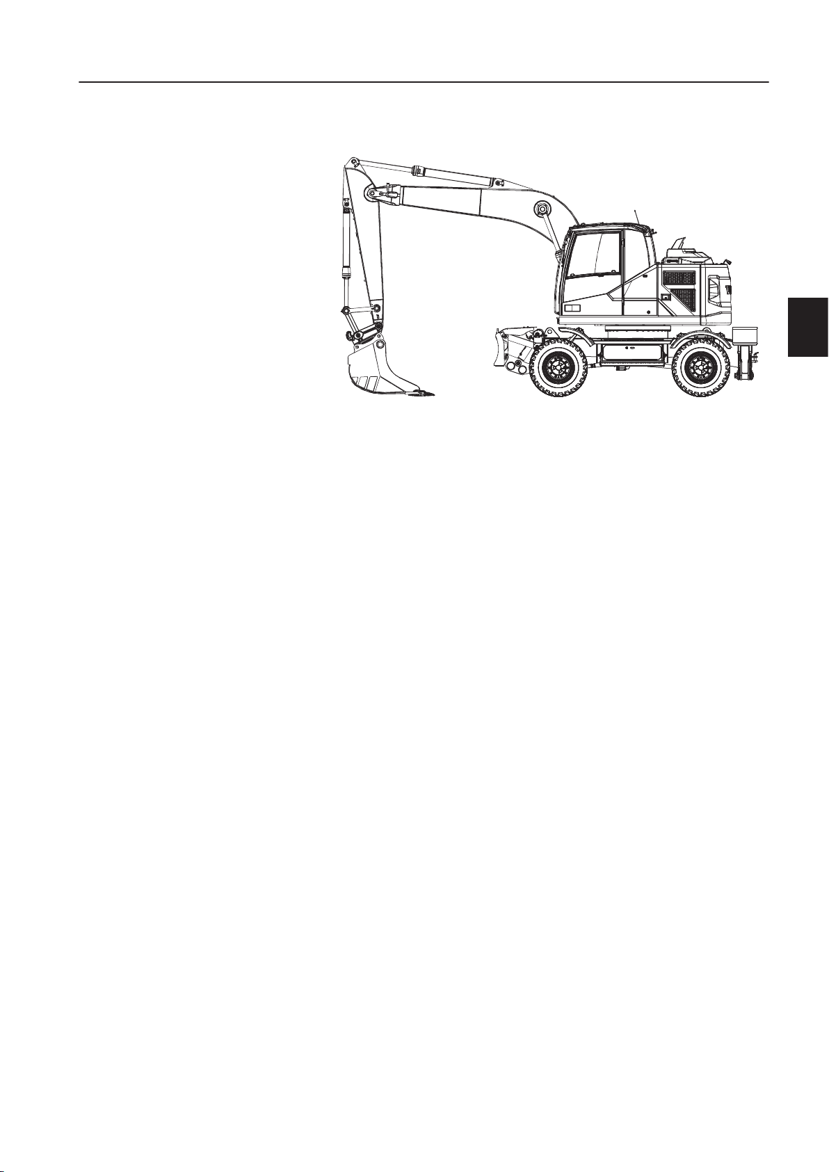
Machine view ..................................................................... 12
CE-marking, EMC-directive ............................................... 13
Communication equipment, installation ............................. 16
Safety components ............................................................ 17
Product plates ................................................................... 18
Information and warning decals ........................................ 19
Instrument panels
Instrument panels
.................................................. 27
.................................................. 27
Instrument panel, left ......................................................... 28
Instrument panel, front ...................................................... 32
Display unit ........................................................................ 39
Instrument panel, right ....................................................... 67
Instrument panel, rear ....................................................... 75
Other controls ........................................................ 76
Controls ............................................................................. 76
Cab .................................................................................... 83
Control lockout system ...................................................... 87
Operator comfort ............................................................... 88
Operating instructions
..........................................
..........................................
117
117
Safety rules when operating ............................................ 119
Measures before operating ............................................. 126
Starting engine ................................................................ 127
Hydraulic system, warming up ........................................ 131
Operating ......................................................................... 132
Braking ............................................................................ 133
Exhaust aftertreatment system ........................................ 135
Stopping .......................................................................... 144
Parking ............................................................................ 145
Retrieving and towing ...................................................... 147
Attachments, alternative lowering ................................... 151
Transporting machine ...................................................... 154
Operating techniques
..........................................
..........................................
159
159
Eco driving ....................................................................... 160
Whole-body vibrations ..................................................... 161
Rules for digging ............................................................. 163
Boom Suspension System (BSS) .................................... 165
Working within dangerous areas ..................................... 167
Attachments .................................................................... 173
Attachments, connecting and disconnecting ................... 181
Pressure release ............................................................. 191
Buckets ............................................................................ 192
Offset boom ..................................................................... 197
Hammer ........................................................................... 198
Lifting objects .................................................................. 200
Equipment towing ............................................................ 204
Signalling diagram ........................................................... 211
Table of contents
Table of contents
3

Safety when servicing ..........................................
214
214
Service position ............................................................... 215
Before service, read ........................................................ 218
Entering, leaving and climbing the machine .................... 221
Fire prevention ................................................................ 223
Handling hazardous materials ......................................... 225
Handling line, tubes and hoses ....................................... 228
Maintenance ........................................................
229
229
Lubrication and service chart .......................................... 236
Maintenance service, every 10 hours .............................. 241
Maintenance service, every 50 hours .............................. 243
Maintenance service, every 100 hours ............................ 251
Maintenance service, every 250 hours ............................ 253
Maintenance service, every 500 hours ............................ 261
Maintenance service, every 1000 hours .......................... 266
Maintenance service, every 2000 hours .......................... 267
Maintenance service, when required ............................... 268
Specifications ......................................................
290
290
Recommended lubricants ................................................ 290
Fuel system ..................................................................... 295
Service capacities and change intervals ......................... 298
Engine ............................................................................. 299
Electrical system ............................................................. 300
Wheels ............................................................................ 304
Cab .................................................................................. 306
Noise and vibrations ........................................................ 307
Hydraulic system ............................................................. 308
Machine weights .............................................................. 309
Dimensions ...................................................................... 310
Working ranges ............................................................... 315
Recommended bucket sizes ........................................... 318
Digging forces ................................................................. 320
Lifting capacities .............................................................. 321
Service history ................................................................. 334
Alphabetical index
Alphabetical index
...............................................
...............................................
337
337
4
Table of contents
Table of contents

5
5

Identification numbers
Make a note below of the identification numbers of the machine and its components. Always state the number
when contacting the manufacturer and when ordering spare parts.
Manufacturer:
Manufacturer:
Volvo Construction Equipment Germany GmbH
D-54329 Konz-Könen
Germany
Machine PIN
(Serial number)
Axles
Travel gearbox
6
Identification numbers

Presentation
Presentation
V1160200
Intended use
Intended use
The machine is intended to be used under normal conditions for
the applications described in this manual. If it is used for other
purposes or in potentially dangerous environments, for example
explosive atmosphere, flammable environment or areas with dust
containing asbestos and so on, special safety regulations must
be followed and the machine be equipped for such use. Contact
the manufacturer / dealer for further information.
Environmental requirements
Be aware of the environment when operating and during service
and maintenance of the machine. Always follow local and national
environmental legislation applicable to all handling of the
machine.
Engine
Engine
D4J is a four stroke, straight, four-cylinder, turbocharged, direct
injected diesel engine with charge air cooling.
In order to reduce nitrogen oxides, particles, hydrocarbons and
carbon monoxide, the engine includes external, cooled exhaust
gas recirculation (EGR) and an exhaust aftertreatment system
(EATS) with AdBlue®/DEF injection.
The exhaust aftertreatment system is a certified spark arrestor in
accordance with Directive 97/68/EC and EN 1834.
AdBlue®/DEF information
AdBlue®/DEF is needed for the reduction of nitrogen oxides
(NOx). AdBlue®/DEF is filled in a separate tank on the machine
that is completely separate from the fuel tank. AdBlue®/DEF must
not be mixed into the diesel tank and diesel must not be mixed
into the AdBlue®/DEF.
For distribution of AdBlue®/DEF (only valid for US market):
- Volvo CE Customer Support: 1-877-823-1111 (business
Volvo CE Customer Support: 1-877-823-1111 (business
hours)
hours)
- www.volvoce.com (outside of business hours)
www.volvoce.com (outside of business hours)
Presentation
Presentation
7

For distribution of AdBlue®/DEF (all other markets), please
contact your local Volvo dealer for more information.
See page
See page
268
268
for information about filling AdBlue®/DEF.
Exhaust aftertreatment system
The engine features an exhaust aftertreatment system (EATS) in
the form of two mufflers. The first one contains a diesel oxidation
catalyst (DOC) and a diesel particulate filter (DPF) to reduce
emissions of particulate matter (PM). The second one contains a
selective catalytic reduction catalyst (SCR) to reduce nitrogen
oxide (NOx) emissions. AdBlue®/DEF is injected into the
exhausts in order to reduce NOx.
The DPF traps particles from the engine exhausts and, since it is
continuously loaded with these particles from the exhausts, it
needs to be regenerated in order to burn off the particles.
A passive regeneration process is constantly oxidizing the soot
particles stored in the DPF.
To achieve the defined emission values the EATS is electronically
controlled and monitored by the aftertreatment control module
(ACM).
For more information, see page
135
.
Electrical system
Electrical system
The machine has different electronic control units for the vehicle,
the IC (Instrument Cluster) and keypads, the climate control, the
engine and the aftertreatment system.
Additionally a caretrack unit is installed if the machine is equipped
with the optional Caretrack-System.
The relays and fuses are grouped in the electrical distribution box
in the cab behind the driver seat under the cover.
Brake system
Brake system
The brake system and the steering system have a common gear
pump, which supplies oil to both circuits. The brake circuit has
priority over the steering circuit.
The brake system is a dual-circuit system with two accumulators,
operated via the servo hydraulics. The system meets the
requirements according to ISO 3450.
In order to prevent immediate loss of brake action, should there
be a loss of servo pressure, there is a brake pressure
accumulator. Therefore it is possible to apply the brakes at least
eight times after the loss of servo pressure.
Service brakes
Service brakes
The service brakes are servo-hydraulically operated, self-
adjusting, wet, multi-disc brakes in two separate brake circuits.
Digging brake
Digging brake
The service brake pedal is also used as digging brake.
Parking brake
Parking brake
The parking brake is a negative action wet disc brake integrated
in the travel gearbox. It is spring applied and pressure released.
8
Presentation
Presentation

Safety system
Safety system
The two-circuit service brakes are supplied with two accumulators
in the event of failure in the service brake system.
Steering system
Steering system
The machine is provided with a hydrostatic steering system.
Cab
Cab
The cab is supported on hydraulic dampening mounts to reduce
shock and vibration levels. A sound absorbing lining provides low
noise levels. The upper windscreen can be pushed up into the
roof. The cab has a sliding window pane in the cab door. The cab
is provided with air filter, recirculation and heating systems. The
cab is also prepared for the installation of FOPS/FOG (optional
equipment).
If any part of the cab’s protective structure is affected by
permanent deformation or rupture, the cab shall be immediately
replaced.
Never carry out any unauthorised alterations to the cab, e.g.
lowering the roof height, drilling, welding on brackets for fire
extinguisher, radio aerial or other equipment, without first, through
a dealer, having discussed the alteration with personnel at the
Volvo Engineering Department. This department will decide
whether the alteration may cause the approval to become void.
It is important that all parties concerned are aware of these
regulations.
Hydraulic system
Hydraulic system
The hydraulic system is load-sensing with variable flow, i.e. the
working pump can deliver flow according to demand. A variable
flow allows precision work even with high engine speed.
Except for a small cooling flow, no oil is pumped around in the
system when the control levers and pedals are not activated. The
oil flow is constantly controlled according to demand.
Among the available functions of the machine are power boost
and float position (optional equipment).
Power boost is used, if additional power is required, for example
during heavy lifting.
The float position (optional equipment) is used when the
attachment is to follow the ground even though it is uneven, e.g.
when exposing underlying rock, clamshell handling and when
emptying barges and truck platforms.
Equipment
Equipment
Depending on the requirements of different markets, the machine
may be provided with different types of optional equipment.
Examples of optional equipment: trailer towing solution (TTS),
boom suspension system (BSS), tiltrotator control system,
different types of attachment brackets, deluxe operator seat,
additional working lights, sun blind, mudguards and much more.
Please contact Volvo distributors for further information about
optional equipment.
Presentation
Presentation
9

Modifications
Modifications
Modifications of this machine, including the use of unauthorized
attachments, accessories, units, or parts, may affect the
machine's integrity (condition) and/or the machine's ability to
function in the way for which it is designed. Persons or
organizations performing unauthorized modifications assume all
responsibility for consequences that arise due to modifications or
can be attributed to modifications, including damaging affect to
the machine.
No modifications of any kind may be performed on this product
unless each specific modification first has been approved in
writing by Volvo Construction Equipment. Volvo Construction
Equipment reserves the right to reject all warranty claims that
have arisen due to or can be traced to unauthorized modifications.
Unauthorised modifications on the upperframe can have an
influence on the ROPS protection system which is intended to
secure the driver in case of an accident.
Modifications may be considered to be officially approved, if at
least one of the following conditions has been met:
1 The attachment, the accessory, the unit, or the part has been
manufactured or distributed by Volvo Construction Equipment
and has been installed according to the factory-approved
method described in a publication available from Volvo
Construction Equipment; or
2 The modification has been approved in writing by the
Engineering Department for the relevant product line at Volvo
Construction Equipment.
Swing drive unit
Swing drive unit
The swing movement of the machine is performed by a
directacting motor with integrated swing brake.
Logged machine data
Logged machine data
The machine is equipped with a software system, which records
various information about the machine and this information is
transferred from the machine to Volvo and used by Volvo and its
authorized workshops in the product development process and
for possible malfunction detection.
Questions regarding this information can be directed to your
dealer.
CareTrack
CareTrack
The machine may be equipped with CareTrack, a telematics
system developed by Volvo Construction Equipment. The system
stores machine data, e.g., machine position, operating hours, fuel
consumption, fuel level, that can be sent by wireless transmission
to a computer. CareTrack is available in different versions,
depending on the required information level.
CareTrack makes it easier to plan for service and reduces costly
downtime. Productivity is improved by knowing if machines are
being operated correctly and how much fuel is being consumed.
CareTrack also allows the customer to restrict the operating area
of the machine, by using virtual fences. This helps to eliminate
unauthorized machine use and theft. For further information,
contact a Volvo Construction Equipment dealer.
10
10
Presentation
Presentation

The CareTrack system transmits data, in the same way a mobile
phone does, with a maximum output rate of 10 W. The transmitter
is always on and the operator cannot switch it off.
Local precautions and restrictions applicable to mobile phones,
for example safety distance, also apply to the CareTrack system.
Tool kit
Tool kit
(optional equipment)
The toolbox is located on the left side of the machine. A second
optional toolbox can be installed on the right side.
The machine comes with a number of tools, see below.
V1148117
8
6
7
5
4
3
2
1
9
- Tool bag (1)
- Grease gun with cartridge (2)
- Extension for grease gun (3)
- Open end wrench (4, 5, 6)
- Screw drivers (7, 8)
- Hydraulic drain hose (9)
- Wheel chocks (optional equipment)
Presentation
Presentation
11
11

Machine view
Machine view
V1160039
1
3
2
5
4
67
8
9
10
9
11
14
13
15
16
12
18
17
EWR150E with two-piece boom
1 AdBlue®/DEF tank 10 Attachment quick coupler
(between dipper arm and bucket)
2 Fuel Tank 11 Bucket
3 Hydraulic oil tank 12 Boom cylinders
4 Side cover 13 Stabiliser legs
5 Counterweight 14 Side cover
6 Engine cover 15 Stabiliser blade
7 First boom on two-piece boom 16 Two-piece boom cylinder
8 Second boom on two-piece boom 17 Bucket cylinder
9 Dipper arm 18 Dipper arm cylinder
12
12
Presentation
Presentation
Machine view
Machine view

CE-marking, EMC-directive
CE marking
CE marking
(Declaration of Conformity : Only applies to machines marketed
(Declaration of Conformity:Only applies to machines marketed
within the EU/EEA.)
within the EU/EEA.)
This machine is CE marked. This means that when delivered the
machine meets the applicable "Essential Health and Safety
Requirements", which are given in the EU Machinery Safety
Directive, 2006/42/EC.
Any person carrying out changes that affect the safety of the
machine, is also responsible for the same.
As proof that the requirements are met, the machine is supplied
with an EU Declaration of Conformity, issued by Volvo CE for
each separate machine. This EU declaration also covers
attachments manufactured by Volvo CE. The documentation is a
valuable document, which should be kept safe and retained for at
least ten years. The document should always accompany the
machine when it is sold.
If the machine is used for other purposes or with other
attachments than described in this manual, safety must at all
times and in each separate case be maintained. The person
carrying out such action is also responsible for the action which,
in some cases, may require a new CE marking and the issue of
a new EU Declaration of Conformity.
V1067840
Presentation
Presentation
CE-marking, EMC-directive 13

EU EMC Directive
EU EMC Directive
The electronic equipment of the machine may in some cases
cause interference to other electronic equipment, or suffer from
external electromagnetic interference, which may constitute
safety risks.
The EU EMC directive about "Electromagnetic compatibility",
2004/108/EC, provides a general description of what demands
can be made on the machine out of a safety point of view, where
permitted limits have been determined and given according to
international standards.
A machine or device which meets the requirements should be CE
marked. Our machines have been tested particularly for
electromagnetic interference. The CE marking of the machine
and the declaration of conformity also cover the EMC directive.
If other electronic equipment is fitted to this machine, the
equipment must be CE marked and tested on the machine with
regard to electromagnetic interference.
14
14
Presentation
Presentation
CE-marking, EMC-directive

EU conformity certificate
We,
We,
Volvo Construction Equipment Germany GmbH
Max-Planck-Straße 1
54329 Konz
Germany
Retention of technical documentation by:
Manager Product Platform Wheeled Excavator
hereby declare that the machine specified below:
Wheeled Excavator
Type
Type
Serial
Serial
number
number
Output
Output
Representative sound power
level (LWA)
level (LWA)
Guaranteed sound power
level (LWA)
level (LWA)
Year of CE
Year of CE
marking
marking
EWR150E 105 Kw 99.4 dB(A) 100 dB(A)
is compliant with the following relevant provisions:
- EC Directive “Machinery” 2006/42/EC
- EC Directive “Noise Emissions” 2000/14/EC
- EC Directive “EMC” 2004/108/EC
- For electric heating/power generator, additionally EC Directive
“Low Voltage” 2006/95/EC
Significant harmonised standards used in connection with this:
- EN 474–1 and 474–5
The Volvo EW160E/EW180E conforms to directive 2000/14/EC
Annex VIII (Full Quality Assurance).
The sound marking is based on issuance of EU Notified Body for
noise measurement carried out by Volvo Construction Equipment
Germany GmbH.
Notified Body:
DGUV; No: 0515
Test Prüf- und Zertifizierungsstelle
D-80687 München (Germany)
Konz, <dd.mm.yyyy>
<N. N.>
Manager Product Platform Wheeled Excavator
Volvo Construction Equipment Germany GmbH
Presentation
Presentation
CE-marking, EMC-directive 15

Communication equipment,
installation
installation
NOTICE
NOTICE
All installation of optional electronic communication equipment
must be performed by trained professionals and in accordance
with the Volvo Construction Equipment instructions.
Protection against electromagnetic interference
This machine has been tested in accordance with EU directive
2004/108/EC governing electromagnetic interference. It is
therefore very important that all non-approved electronic
accessories, such as communication equipment, should be
tested before installation and use, since they can cause
interference to the electronic systems of the machine.
Guidelines
Guidelines
The following guidelines must be followed during installation:
The antenna placement must be chosen to give good
adaptation to the surroundings.
The antenna cable must be of the coaxial type. Be careful to
ensure that the cable is undamaged, that the sheath and braid
are not split at the ends, the braid covers the connector ferrules
and has good galvanic contact with them.
The mating surface between the antenna mounting bracket
and the bodywork must have clean metal surfaces, with all dirt
and oxide removed. Protect the mating surfaces against
corrosion after installation to maintain good galvanic contact.
Remember to separate interfering and interfered cables
physically. Interfering cables consist of the communication
equipment's supply cables and antenna cable. Interfered
cables are those which are connected to electronic devices in
the machine. Install the cables as close as possible to earthed
(grounded) sheet metal surfaces, since the sheet metal has a
shielding effect.
16
16
Presentation
Presentation
Communication equipment, installation

Safety components
Safety components
Genuine Volvo spare parts guarantee the best service life,
reliability, and safety for the machine and operator. If reliable and
purpose-built parts are not used, your safety, health, and the
machine's function may be compromised. Contact your dealer
and state the machine's model designation/serial number (PIN-
number) when ordering spare parts. Position of PIN-plate, see
section "Product plates".
Your Volvo dealer always has up-to-date spare part information
that is updated at regular intervals via the information system
PROSIS.
Safety-classified machine and spare parts
Safety-classified machine and spare parts means that the
components are intended to fulfil a safety function.
Examples of safety-classified machine parts/spare parts
Removable protective devices/guards over rotating parts and
hot surfaces
Protective plates, rails, covers, and steps
Components included in systems to reduce sound and
vibrations
Components included in systems to improve the operator's
visibility
Complete operator's seat incl. lap-type seatbelt
Decals and plates
Cab filter
NOTE!
NOTE!
Safety-classified machine and spare parts shall be reinstalled,
repaired, or replaced immediately if they have been removed or
damaged.
When changing machine operator/owner, malfunctions and
defects of safety-classified machine and spare parts shall be
reported immediately and an action plan shall be established.
There is more important information in this Operator's manual
about the components that are considered safety-classified.
Presentation
Presentation
Safety components 17

Product plates
Product plates
When ordering spare parts, and in all telephone enquiries or
correspondence the model designation and the Product
Identification Number (PIN) must always be quoted.
Product plate
Product plate
The product plate on the machine shows the manufacturer's
name and address, model designation, PIN, machine weight,
engine output and the manufacturing year. The plate is
positioned under the boom on the superstructure frame.
The EPA plate is positioned under the boom on the
superstructure frame (North America only).
Engine product plate
The engine product plate contains type designation and part
and serial numbers and is positioned on the engine.
Travel gearbox product plate
The gearbox product plate contains type designation and part
and serial numbers and is positioned on the travel gearbox.
Axle product plate
Axle product plate
The axle product plate contains type designation and part and
serial numbers and is positioned on each axle.
V1148961
V|C|E|W|1|6|0|E|X|B|0|3|2|0|0|0|1
AB CE
Example of PIN number on PIN plate
A Volvo Construction Equipment
B Machine type
C Check letters
D Serial number
18
18
Presentation
Presentation
Product plates
Product plates
Other manuals for EWR150E
1
Table of contents
Other Volvo Excavator manuals