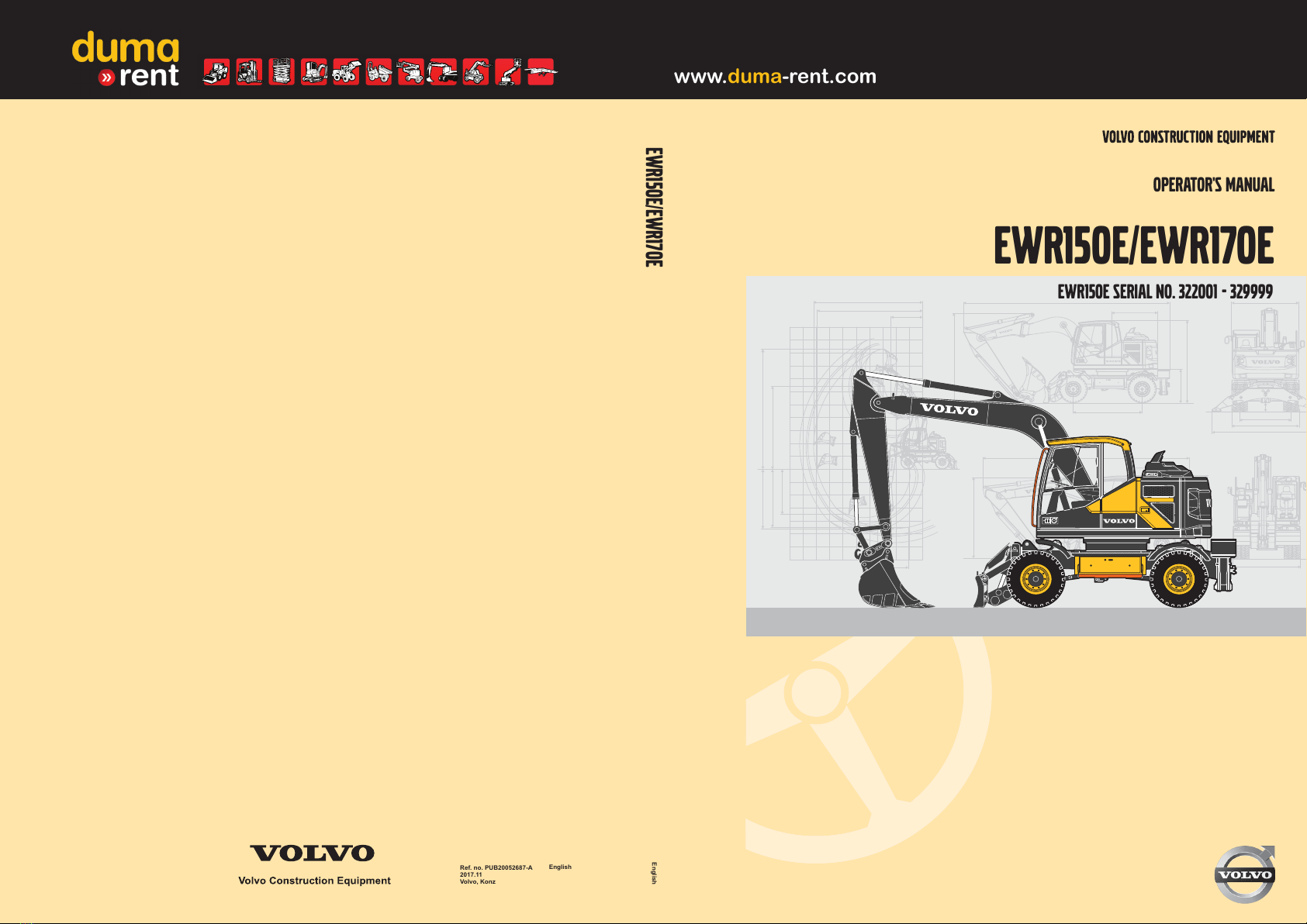
Volvo EWR150E User manual

EWR150E/EWR170E
EWR150E/EWR170E
operator's manual
Ref. no. PUB20052687-A
2017.11
Volvo, Konz
English
English
EWR150E Serial No. 322001 - 329999
www.duma-rent.com

California
Proposition 65 Warning
Diesel engine exhaust and some of its constituents are
known to the State of California to cause cancer, birth
defects, and other reproductive harm.
California
Proposition 65 Warning
Battery posts, terminals and other related accessories
contain lead and lead compounds, chemicals known
to the State of California to cause cancer and other
reproductive harm.
Wash hands after handling.
www.duma-rent.com

F
Foreword
This operator's manual is intended as a guide for the correct use and
maintenance of the machine. Read this manual carefully before you start
and move the machine or before you carry out any preventive
maintenance.
Keep this manual in the lockable storage compartment so that it is always
available for easy reference. Replace it immediately if it is lost.
The operator's manual describes the applications for which the machine
was primarily designed. It has been written to be valid on all markets.
Therefore, please ignore any sections which do not relate to your machine
or to the work that you do with your machine.
N
O
O
T
T
E
E!
If the manual covers more than one machine, the information relates to all
machines unless otherwise specified.
When designing this machine, much time has been invested in achieving
the best possible efficiency and safety. But accidents do happen, and most
of them can be attributed to human error. A safety-conscious person and
a well-maintained machine make up a reliable, powerful, and profitable
combination. T
T
h
h
e
e
r
ref
o
ore, re
a
ad t
h
h
e
esa
f
f
e
e
t
t
y
y
i
i
n
n
s
st
r
r
u
uct
i
io
n
ns a
n
n
d
df
o
o
l
l
l
l
o
ow t
h
he
m
m.
We constantly strive to develop and improve the efficiency of our products
by making changes to their design. We reserve the right to make design
modifications to the products even after they have been delivered. Also,
we reserve the right to change data and equipment, as well as the service
and maintenance instructions, without prior notice.
OPERATOR'S MANUAL
Ta
b
b
l
l
e
e
o
o
f
f
c
co
n
n
t
t
e
e
n
n
t
t
s
s
P
r
r
e
e
s
se
n
n
t
t
a
a
t
t
i
i
o
o
n
n
I
n
n
s
st
r
r
u
u
m
m
e
e
n
n
t
tp
a
a
n
n
e
e
l
l
s
s
O
t
t
h
h
e
e
r
r
c
co
n
n
t
t
r
r
o
o
l
l
s
s
O
p
p
e
e
r
r
a
a
t
t
i
i
n
n
g
g
i
i
n
n
s
st
r
r
u
u
c
ct
i
i
o
o
n
n
s
s
O
p
p
e
e
r
r
a
a
t
t
i
i
n
n
g
g
t
t
e
e
c
ch
n
n
i
i
q
q
u
u
e
e
s
s
S
a
a
f
f
e
e
t
t
y
yw
h
h
e
e
n
n
s
se
r
r
v
vi
c
ci
n
n
g
g
M
a
a
i
i
n
n
t
t
e
e
n
n
a
a
n
n
c
ce
S
p
p
e
e
c
ci
f
f
i
i
c
ca
t
t
i
i
o
o
n
n
s
s
A
l
l
p
p
h
h
a
a
b
b
e
e
t
t
i
i
c
ca
l
l
i
i
n
n
d
d
e
e
x
x
EWR150E/EWR170E (EWR150E Serial No. 322001 - 329999)
Ref. No. 20052687-A
The original language is English. Original instructions.
2017.11
C
o
o
p
p
y
yr
i
i
g
gh
t
t© 2
0
01
7
7
,
,V
o
ol
v
vo C
o
o
n
nst
r
r
u
uct
i
i
o
o
n
nE
q
q
u
u
i
i
p
pm
e
e
n
nt
.
.A
l
l
l
lr
i
i
g
g
h
h
t
t
s
sr
e
e
s
se
r
r
v
ved.
www.duma-rent.com

S
Safety regulations
The machine operator is responsible for being aware of and complying
with the relevant, legally prescribed, national and regional safety
instructions. The safety instructions in this operator's manual are
applicable only in cases where no legislated safety instructions are in
force.
D
A
A
N
N
G
G
E
E
R
R
The safety symbol combined with this signal word indicates a hazardous
situation which, if not avoided,
w
i
i
l
l
l
lre
s
su
l
l
t
ti
n
nd
e
e
a
a
t
th o
r
rse
r
ri
o
o
u
u
s
si
n
n
j
j
u
u
r
ry.
Danger
is limited to the most extreme situations.
W
A
A
R
R
N
N
I
I
N
N
G
G
The safety symbol combined with this signal word indicates a hazardous
situation which, if not avoided, could result in
dea
t
t
h
hor se
r
riou
s
si
n
nju
r
ry
.
C
A
A
U
U
T
T
I
I
O
O
N
N
The safety symbol combined with this signal word indicates a hazardous
situation which, if not avoided, could result in
mo
d
d
e
e
r
ra
t
t
e
eor mi
n
nor i
n
n
j
j
u
ury
.
N
O
O
T
T
I
I
C
C
E
E
I
I
n
n
d
d
i
i
c
ca
t
t
e
e
s
sa p
o
o
t
t
e
e
n
n
t
t
i
ia
l
l
l
l
y
yh
a
azard
o
ou
s
ssi
t
t
u
u
a
a
t
t
i
io
n
nw
h
hich ma
y
yre
s
su
l
l
t
ti
n
nmachin
e
e
d
a
a
m
ma
g
g
e
e
.
.
N
O
O
T
T
E
E!
Used in order to refer to installation, operating, or maintenance information
which is important but not danger-related.
G
e
e
t
tt
o
okn
o
o
w
wt
h
h
e
eca
p
p
a
a
c
ci
t
t
y
ya
n
n
d
dl
i
i
m
m
i
i
t
t
s
so
f
fyo
u
u
r
rm
a
a
c
ch
i
i
n
n
e
e
!
!
2
F
o
o
r
r
e
e
w
w
o
o
r
r
d
d
www.duma-rent.com

T
Table of contents
Foreword ................................................................. 1
Identification numbers ......................................................... 6
P
r
r
e
e
s
se
n
n
t
t
a
a
t
t
i
i
o
o
n
n.
.
.
.
.
.
.
.
.
.
.
.
.
.
.
.
.
.
.
.
.
.
.
.
.
.
.
.
.
.
.
.
.
.
.
.
.
.
.
.
.
.
.
.
.
.
.
.
.
.
.
.
.
.
.
.
.
.
.
.
.
.
.
.
.
.
.
.
.
.
.
.
.
.
.
.
.
.
.
.
.
.
.
.
.
.
.
.
.
.
.
.
.
.
.
.
.
.
.
.
.
.
.
.
.
.
.
.
.
.
.
.
.
.
.
.
.
.
.7
Machine view ..................................................................... 12
CE-marking, EMC-directive ............................................... 13
Communication equipment, installation ............................. 16
Safety components ............................................................ 17
Product plates ................................................................... 18
Information and warning decals ........................................ 19
USA federal clean air act ................................................... 27
I
n
n
s
st
r
r
u
u
m
m
e
e
n
n
t
tp
a
a
n
n
e
e
l
l
s
s.
.
.
.
.
.
.
.
.
.
.
.
.
.
.
.
.
.
.
.
.
.
.
.
.
.
.
.
.
.
.
.
.
.
.
.
.
.
.
.
.
.
.
.
.
.
.
.
.
.
.
.
.
.
.
.
.
.
.
.
.
.
.
.
.
.
.
.
.
.
.
.
.
.
.
.
.
.
.
.
.
.
.
.
.
.
.
.
.
.
.
.
.
.
.
.
.
.
.3
1
1
Instrument panel, left ......................................................... 32
Instrument panel, front ...................................................... 37
Display unit ........................................................................ 44
Instrument panel, right ....................................................... 78
Instrument panel, rear ....................................................... 87
O
t
t
h
h
e
e
r
rco
n
n
t
t
r
r
o
o
l
l
s
s.
.
.
.
.
.
.
.
.
.
.
.
.
.
.
.
.
.
.
.
.
.
.
.
.
.
.
.
.
.
.
.
.
.
.
.
.
.
.
.
.
.
.
.
.
.
.
.
.
.
.
.
.
.
.
.
.
.
.
.
.
.
.
.
.
.
.
.
.
.
.
.
.
.
.
.
.
.
.
.
.
.
.
.
.
.
.
.
.
.
.
.
.
.
.
.
.
.
.
.
.
.
.
.
.
.
.
.
.
.
.8
8
8
Controls ............................................................................. 88
Cab .................................................................................. 100
Control lockout system .................................................... 104
Operator comfort ............................................................. 105
O
p
p
e
e
r
r
a
a
t
t
i
i
n
n
g
gi
n
n
s
st
r
r
u
u
c
ct
i
i
o
o
n
n
s
s.
.
.
.
.
.
.
.
.
.
.
.
.
.
.
.
.
.
.
.
.
.
.
.
.
.
.
.
.
.
.
.
.
.
.
.
.
.
.
.
.
.
.
.
.
.
.
.
.
.
.
.
.
.
.
.
.
.
.
.
.
.
.
.
.
.
.
.
.
.
.
.
.
.
.
.
.
.
.
.
.
.
.1
3
3
3
3
Safety rules when operating ............................................ 139
Measures before operating ............................................. 145
Starting engine ................................................................ 146
Hydraulic system, warming up ........................................ 150
Operating ......................................................................... 151
Steering ........................................................................... 153
Braking ............................................................................ 156
Exhaust aftertreatment system ........................................ 158
Stopping .......................................................................... 168
Parking ............................................................................ 169
Retrieving and towing ...................................................... 171
Attachments, alternative lowering ................................... 175
Transporting machine ...................................................... 178
O
p
p
e
e
r
r
a
a
t
t
i
i
n
n
g
gt
e
e
c
ch
n
n
i
i
q
q
u
u
e
e
s
s.
.
.
.
.
.
.
.
.
.
.
.
.
.
.
.
.
.
.
.
.
.
.
.
.
.
.
.
.
.
.
.
.
.
.
.
.
.
.
.
.
.
.
.
.
.
.
.
.
.
.
.
.
.
.
.
.
.
.
.
.
.
.
.
.
.
.
.
.
.
.
.
.
.
.
.
.
.
.
.
.
.
.1
8
8
3
3
Eco driving ....................................................................... 184
Whole-body vibrations ..................................................... 185
Rules for digging ............................................................. 187
Boom Suspension System (BSS) .................................... 189
Working within dangerous areas ..................................... 191
Attachments .................................................................... 199
Attachments, connecting and disconnecting ................... 202
Pressure release ............................................................. 213
Buckets ............................................................................ 214
Offset boom ..................................................................... 219
Hammer ........................................................................... 220
Lifting objects .................................................................. 222
Equipment towing ............................................................ 226
Signalling diagram ........................................................... 235
T
Ta
b
b
l
l
e
eo
f
fco
n
n
t
t
e
e
n
n
t
t
s
s
3
www.duma-rent.com

S
Safety when servicing .......................................... 238
Service position ............................................................... 239
Before service, read ........................................................ 241
Entering, leaving and climbing the machine .................... 246
Fire prevention ................................................................ 248
Handling hazardous materials ......................................... 250
Handling line, tubes and hoses ....................................... 254
M
a
a
i
i
n
n
t
t
e
e
n
n
a
a
n
n
c
ce .
.
.
.
.
.
.
.
.
.
.
.
.
.
.
.
.
.
.
.
.
.
.
.
.
.
.
.
.
.
.
.
.
.
.
.
.
.
.
.
.
.
.
.
.
.
.
.
.
.
.
.
.
.
.
.
.
.
.
.
.
.
.
.
.
.
.
.
.
.
.
.
.
.
.
.
.
.
.
.
.
.
.
.
.
.
.
.
.
.
.
.
.
.
.
.
.
.
.
.
.
.
.
.
.
.
.
.
.
.
.2
5
5
5
5
Lubrication and service chart .......................................... 259
Maintenance service, every 10 hours .............................. 264
Maintenance service, every 50 hours .............................. 266
Maintenance service, every 100 hours ............................ 275
Maintenance service, every 250 hours ............................ 279
Maintenance service, every 500 hours ............................ 286
Maintenance service, every 1000 hours .......................... 291
Maintenance service, every 2000 hours .......................... 292
Maintenance service, when required ............................... 293
S
p
p
e
e
c
ci
f
f
i
i
c
ca
t
t
i
i
o
o
n
n
s
s.
.
.
.
.
.
.
.
.
.
.
.
.
.
.
.
.
.
.
.
.
.
.
.
.
.
.
.
.
.
.
.
.
.
.
.
.
.
.
.
.
.
.
.
.
.
.
.
.
.
.
.
.
.
.
.
.
.
.
.
.
.
.
.
.
.
.
.
.
.
.
.
.
.
.
.
.
.
.
.
.
.
.
.
.
.
.
.
.
.
.
.
.
.
.
.
.
.
.
.
.
.
.
.
.
.
.3
1
1
7
7
Recommended lubricants ................................................ 317
Fuel system ..................................................................... 324
Service capacities and change intervals ......................... 330
Engine ............................................................................. 333
Electrical system ............................................................. 334
Wheels ............................................................................ 338
Cab .................................................................................. 341
Noise and vibrations ........................................................ 342
Hydraulic system ............................................................. 343
Machine weights .............................................................. 344
Dimensions ...................................................................... 345
Working ranges ............................................................... 354
Recommended bucket sizes ........................................... 359
Digging forces ................................................................. 364
Lifting capacities .............................................................. 366
Service history ................................................................. 383
A
l
l
p
p
h
h
a
a
b
b
e
e
t
t
i
i
c
ca
l
li
n
n
d
d
e
e
x
x.
.
.
.
.
.
.
.
.
.
.
.
.
.
.
.
.
.
.
.
.
.
.
.
.
.
.
.
.
.
.
.
.
.
.
.
.
.
.
.
.
.
.
.
.
.
.
.
.
.
.
.
.
.
.
.
.
.
.
.
.
.
.
.
.
.
.
.
.
.
.
.
.
.
.
.
.
.
.
.
.
.
.
.
.
.
.
.
.
.
.
.
.3
8
8
5
5
4
Ta
b
b
l
l
e
eo
f
fco
n
n
t
t
e
e
n
n
t
t
s
s
www.duma-rent.com

5
5
www.duma-rent.com

I
Identification numbers
Make a note below of the identification numbers of the machine and its components. Always state the number
when contacting the manufacturer and when ordering spare parts.
Ma
n
n
u
u
f
f
a
a
c
ct
u
u
r
re
r
r:
Volvo Construction Equipment Germany GmbH
D-54329 Konz-Könen
Germany
Machine PIN
(Serial number)
Axles
Travel gearbox
6I
d
d
e
e
n
n
t
t
i
i
f
f
i
i
c
ca
t
t
i
i
o
o
n
nn
u
u
m
m
b
b
e
e
r
r
s
s
www.duma-rent.com

P
Presentation
V1184106
I
n
n
t
te
n
n
d
d
e
e
d
du
s
se
The machine is intended to be used under normal conditions for
the applications described in this manual. If it is used for other
purposes or in potentially dangerous environments, for example
explosive atmosphere, flammable environment or areas with dust
containing asbestos and so on, special safety regulations must
be followed and the machine be equipped for such use. Contact
the manufacturer / dealer for further information.
E
n
n
v
vir
o
o
n
n
m
m
e
e
n
n
t
t
a
a
l
lr
e
e
q
q
u
u
i
i
r
r
e
e
m
m
e
e
n
n
t
t
s
s
Be aware of the environment when operating and during service
and maintenance of the machine. Always follow local and national
environmental legislation applicable to all handling of the
machine.
E
n
n
g
g
i
in
e
e
The machine is equipped with a straight four cylinder, four-stroke,
turbocharged diesel engine with direct injection and charge air
cooler.
In order to reduce nitrogen oxides, particles, hydrocarbons and
carbon monoxide, the engine includes external, cooled exhaust
gas recirculation (EGR) and an exhaust aftertreatment system
(EATS) with AdBlue®/DEF injection.
The exhaust aftertreatment system is a certified spark arrestor in
accordance with Directive 97/68/EC and EN 1834.
A
d
d
B
B
l
lu
e
e
®
®
/
/
D
DE
F
Fin
f
f
o
o
r
r
m
m
a
a
t
t
i
io
n
n
AdBlue®/DEF is needed for the reduction of nitrogen oxides
(NOx). AdBlue®/DEF is filled in a separate tank on the machine
that is completely separate from the fuel tank. AdBlue®/DEF must
not be mixed into the diesel tank and diesel must not be mixed
into the AdBlue®/DEF.
F
o
o
r
rdi
s
st
r
rib
u
u
t
t
i
i
o
o
n
nof Ad
B
B
l
l
u
ue®
/
/
D
DE
F
F(o
n
n
l
l
y
yval
i
id f
o
o
r
rUS ma
r
rke
t
t
)
):
-V
Volvo CE Customer Support: 1-877-823-1111 (business
hours)
-w
www.volvoce.com (outside of business hours)
Presentation
7
www.duma-rent.com

F
For distribution of AdBlue®/DEF (all other markets), pl
e
ease
contact your local Volvo dealer for more information.
See page
293
f
for information about filling AdBlue®/DEF.
Exhaust aftertreatment system
The engine features an exhaust aftertreatment system (EATS) in
the form of two mufflers. The first one contains a diesel oxidation
catalyst (DOC) and a diesel particulate filter (DPF) to reduce
emissions of particulate matter (PM). The second one contains a
selective catalytic reduction catalyst (SCR) to reduce nitrogen
oxide (NOx) emissions. AdBlue®/DEF is injected into the
exhausts in order to reduce NOx.
The DPF traps particles from the engine exhausts and, since it is
continuously loaded with these particles from the exhausts, it
needs to be regenerated in order to burn off the particles.
A passive regeneration process is constantly oxidizing the soot
particles stored in the DPF.
To achieve the defined emission values the EATS is electronically
controlled and monitored by the aftertreatment control module
(ACM).
For more information, see page
158
.
E
E
l
le
c
ct
r
r
i
ica
l
lsyst
e
e
m
m
The machine is equipped with the Volvo CEA2+ (Common
Electronic Architecture 2+) electrical system, a computerized
monitoring and control system.
The different control units are communicating via bus systems.
R
e
e
l
l
a
a
y
ys a
n
n
d
df
u
u
s
se
s
s
The relays and fuses are grouped in the electrical distribution box
in the cab behind the driver seat under the cover.
B
r
r
a
a
k
ke syst
e
e
m
m
The brake system is a dual-circuit system with two accumulators,
operated via the servo hydraulics.
In order to prevent immediate loss of brake action, should there
be a loss of servo pressure, there is a brake pressure
accumulator. Therefore it is possible to apply the brakes at least
eight times after the loss of servo pressure.
S
e
e
r
r
v
vi
c
ce b
r
r
a
a
k
ke
s
s
The service brakes are servo-hydraulically operated, self-
adjusting, wet, multi-disc brakes in two separate brake circuits.
D
i
i
g
g
g
g
i
i
n
n
g
gb
r
r
a
a
k
ke
The service brake pedal is also used as digging brake.
P
a
a
r
r
k
ki
n
n
g
gb
r
r
a
a
k
ke
The parking brake is a negative action wet disc brake integrated
in the travel gearbox. It is spring applied and pressure released.
S
t
t
e
e
e
e
r
r
i
in
g
gsyst
e
e
m
m
The machine is provided with a hydrostatic steering system.
As an optional equipment the machine can feature a Comfort
Drive Control (CDC) function for control lever steering.
8
P
r
r
e
e
s
se
n
n
t
t
a
a
t
t
i
i
o
o
n
n
www.duma-rent.com

C
Cab
The cab is supported on hydraulic dampening mounts to reduce
shock and vibration levels. A sound absorbing lining provides low
noise levels. The upper windscreen can be pushed up into the
roof. The cab has a sliding window pane in the cab door. The cab
is provided with air filter, recirculation and heating systems. The
cab is also prepared for the installation of FOPS/FOG (optional
equipment).
If any part of the cab’s protective structure is affected by
permanent deformation or rupture, the cab shall be immediately
replaced.
Never carry out any unauthorised alterations to the cab, e.g.
lowering the roof height, drilling, welding on brackets for fire
extinguisher, radio aerial or other equipment, without first, through
a dealer, having discussed the alteration with personnel at the
Volvo Engineering Department. This department will decide
whether the alteration may cause the approval to become void.
It is important that all parties concerned are aware of these
regulations.
Hyd
r
r
a
a
u
u
l
lic syst
e
e
m
m
The machine has a load independent flow sharing hydraulic
system which always ensures that each movement receives oil
according to the demand and no function stops.
The diesel engine drives the machine´s working pump, which
gives a hydraulic flow to the working hydraulics and the travel
motor.
The double gear pump is mounted behind the working pump and
supplies the servo, brake and steering hydraulics.
E
q
q
u
u
i
ip
m
m
e
e
n
n
t
t
Depending on the requirements of different markets, the machine
may be provided with different types of optional equipment.
Examples of optional equipment: Comfort Drive Control (CDC),
Volvo Dig Assist, trailer towing solution (TTS), boom suspension
system (BSS), tiltrotator control system, different types of
attachment brackets, deluxe operator seat, additional working
lights, sun blind, mudguards and much more. Please contact
Volvo distributors for further information about optional
equipment.
M
o
o
d
d
i
i
f
f
i
i
c
ca
t
t
i
io
n
n
s
s
Modifications of this machine, including the use of unauthorized
attachments, accessories, units, or parts, may affect the
machine's integrity (condition) and/or the machine's ability to
function in the way for which it is designed. Persons or
organizations performing unauthorized modifications assume all
responsibility for consequences that arise due to modifications or
can be attributed to modifications, including damaging affect to
the machine.
No modifications of any kind may be performed on this product
unless each specific modification first has been approved in
writing by Volvo Construction Equipment. Volvo Construction
Equipment reserves the right to reject all warranty claims that
have arisen due to or can be traced to unauthorized modifications.
P
P
r
r
e
e
s
se
n
n
t
t
a
a
t
t
i
i
o
o
n
n
9
www.duma-rent.com

Unauthorised modifications on the upperframe can have an
influence on the ROPS protection system which is intended to
secure the driver in case of an accident.
Modifications may be considered to be officially approved, if at
least one of the following conditions has been met:
1 The attachment, the accessory, the unit, or the part has been
manufactured or distributed by Volvo Construction Equipment
and has been installed according to the factory-approved
method described in a publication available from Volvo
Construction Equipment; or
2 The modification has been approved in writing by the
Engineering Department for the relevant product line at Volvo
Construction Equipment.
S
S
w
w
i
in
g
gd
r
r
i
ive u
n
n
i
it
The swing movement of the machine is performed by a
directacting motor with integrated swing brake.
L
o
o
g
g
g
g
e
e
d
dm
a
a
c
ch
i
in
e
ed
a
a
t
t
a
a
The machine is equipped with a software system, which records
various information about the machine and this information is
transferred from the machine to Volvo and used by Volvo and its
authorized workshops in the product development process and
for possible malfunction detection.
Questions regarding this information can be directed to your
dealer.
C
a
a
r
r
e
e
T
T
r
r
a
a
c
ck
The machine may be equipped with CareTrack, a telematics
system developed by Volvo Construction Equipment. The system
stores machine data, e.g., machine position, operating hours, fuel
consumption, fuel level, that can be sent by wireless transmission
to a computer. CareTrack is available in different versions,
depending on the required information level.
CareTrack makes it easier to plan for service and reduces costly
downtime. Productivity is improved by knowing if machines are
being operated correctly and how much fuel is being consumed.
CareTrack also allows the customer to restrict the operating area
of the machine, by using virtual fences. This helps to eliminate
unauthorized machine use and theft. For further information,
contact a Volvo Construction Equipment dealer.
The CareTrack system transmits data, in the same way a mobile
phone does, with a maximum output rate of 10 W. The transmitter
is always on and the operator cannot switch it off.
Local precautions and restrictions applicable to mobile phones,
for example safety distance, also apply to the CareTrack system.
To
o
o
l
lkit
(
o
o
p
p
t
t
i
i
o
o
n
n
a
a
l
le
q
q
u
u
i
i
p
p
m
m
e
e
n
n
t
t
)
)
The machine can be equipped with different toolbox options:
- standard toolbox
(either on left hand side or on both sides)
- drawer type toolbox
(on left hand side, right hand side or both sides)
1
0
0
P
r
r
e
e
s
se
n
n
t
t
a
a
t
t
i
i
o
o
n
n
www.duma-rent.com

T
Toolbox content
A daily maintenance kit is an optional equipment which contains
the following tools:
V1183891
3
2
6
5
4
1
8
7
- Tool bag for daily maintenance kit (1)
- Screwdrivers (2 and 3)
- Grease gun with extension (4 and 5)
- 8 open-end wrenches in different sizes (6)
- Allen wrench (7)
- Drain hose (8) (standard equipment)
- Wheel chocks (optional equipment)
P
r
r
e
e
s
se
n
n
t
t
a
a
t
t
i
i
o
o
n
n
1
1
1
www.duma-rent.com

M
Machine view
12
345
14
67
8
9
10
1213
16 17
20
15
V1184107
19
18
11
1 Counterweight 11 AdBlue®/DEF tank
2 Side cover 12 Fuel tank
3 First boom on two-piece boom 13 Hydraulic oil tank
4 Boom cylinders 14 Two-piece boom cylinder
5 Second boom on two-piece boom 15 Boom on mono-block boom
6 Dipper arm cylinder 16 Boom cylinder on mono-block boom
7 Dipper arm 17 Side cover
8 Bucket cylinder 18 Engine cover
9 Attachment quick coupler
(between dipper arm and bucket)
19 Stabiliser legs
10 Bucket 20 Stabiliser blade
1
2
2
P
r
r
e
e
s
se
n
n
t
t
a
a
t
t
i
i
o
o
n
n
M
a
a
c
ch
i
i
n
n
e
evi
e
e
w
w
www.duma-rent.com

C
CE-marking, EMC-directive
CE marking
(Declaration of Conformity : Only applies to machines marketed
within the EU/EEA.)
This machine is CE marked. This means that when delivered the
machine meets the applicable "Essential Health and Safety
Requirements", which are given in the EU Machinery Safety
Directive, 2006/42/EC.
Any person carrying out changes that affect the safety of the
machine, is also responsible for the same.
As proof that the requirements are met, the machine is supplied
with an EU Declaration of Conformity, issued by Volvo CE for
each separate machine. This EU declaration also covers
attachments manufactured by Volvo CE. The documentation is a
valuable document, which should be kept safe and retained for at
least ten years. The document should always accompany the
machine when it is sold.
If the machine is used for other purposes or with other
attachments than described in this manual, safety must at all
times and in each separate case be maintained. The person
carrying out such action is also responsible for the action which,
in some cases, may require a new CE marking and the issue of
a new EU Declaration of Conformity.
V1067840
P
r
r
e
e
s
se
n
n
t
t
a
a
t
t
i
i
o
o
n
n
C
E
E
-
-
m
m
a
a
r
r
k
ki
n
n
g
g
,
,E
M
M
C
C
-
-
d
d
i
i
r
r
e
e
c
ct
i
i
v
ve 1
3
3
www.duma-rent.com

E
EU EMC Directive
The electronic equipment of the machine may in some cases
cause interference to other electronic equipment, or suffer from
external electromagnetic interference, which may constitute
safety risks.
The EU EMC directive about "Electromagnetic compatibility",
2014/30/EU, provides a general description of what demands can
be made on the machine out of a safety point of view, where
permitted limits have been determined and given according to
international standards.
A machine or device which meets the requirements should be CE
marked. Our machines have been tested particularly for
electromagnetic interference. The CE marking of the machine
and the declaration of conformity also cover the EMC directive.
If other electronic equipment is fitted to this machine, the
equipment must be CE marked and tested on the machine with
regard to electromagnetic interference.
1
4
4
P
r
r
e
e
s
se
n
n
t
t
a
a
t
t
i
i
o
o
n
n
C
E
E-
m
m
a
a
r
r
k
ki
n
n
g
g
,
,E
M
M
C
C
-
-
d
d
i
i
r
r
e
e
c
ct
i
i
v
ve
www.duma-rent.com

E
EU conformity certificate
We,
Volvo Construction Equipment Germany GmbH
Max-Planck-Straße 1
54329 Konz
Germany
Retention of technical documentation by:
Manager Product Platform Wheeled Excavator
h
e
e
r
re
b
b
y
yd
e
ecl
a
are t
h
h
a
at t
h
he ma
c
ch
i
i
n
n
e
esp
e
ecif
i
ie
d
db
e
e
l
low
:
:
Wheeled Excavator
T
y
yp
e
eSeri
a
al
n
u
umbe
r
r
O
u
u
t
t
p
put Re
p
presen
t
t
a
at
i
i
v
ve so
u
u
n
nd p
o
ow
e
er
l
e
evel (L
W
W
A
A)
G
u
uara
n
n
t
t
e
eed soun
d
dp
o
o
w
w
e
e
r
r
l
e
e
v
vel (L
W
W
A
A
)
)
Ye
a
ar of C
E
E
ma
r
rkin
g
g
EWR150E 105 Kw 99 dB(A) 100 dB(A)
EWR170E 115 Kw 99 dB(A) 100 dB(A)
EWR170E
Tropical cooling
115 Kw 100 dB(A) 101 dB(A)
i
s
sco
m
mplia
n
n
t
tw
i
i
t
t
h
ht
h
he f
o
o
l
l
l
l
o
ow
i
i
n
ng relevant p
r
ro
v
visi
o
o
n
ns:
- EC Directive “Machinery” 2006/42/EC
- EC Directive “Noise Emissions” 2000/14/EC
- EU Directive “EMC” 2014/30/EU
- For electric heating/power generator, additionally EC Directive
“Low Voltage” 2006/95/EC
Significant harmonised standards used in connection with this:
- EN 474–1 and 474–5
The Volvo EWR150E/EWR170E conforms to directive
2000/14/EC Annex VIII (Full Quality Assurance).
The sound marking is based on issuance of EU Notified Body for
noise measurement carried out by Volvo Construction Equipment
Germany GmbH.
Notified Body:
DGUV; No: 0515
Test Prüf- und Zertifizierungsstelle
D-80687 München (Germany)
Konz, <dd.mm.yyyy>
<N. N.>
Manager Product Platform Wheeled Excavator
Volvo Construction Equipment Germany GmbH
P
r
r
e
e
s
se
n
n
t
t
a
a
t
t
i
i
o
o
n
n
C
E
E
-
-
m
m
a
a
r
r
k
ki
n
n
g
g
,
,E
M
M
C
C
-
-
d
d
i
i
r
r
e
e
c
ct
i
i
v
ve 1
5
5
www.duma-rent.com

C
Communication equipment,
installation
NOT
I
ICE
A
All installation of optional electronic communication equipment
must be performed by trained professionals and in accordance
with the Volvo Construction Equipment instructions.
Protection against electromagnetic interference
This machine has been tested in accordance with EU directive
2014/30/EC governing electromagnetic interference. It is
therefore very important that all non-approved electronic
accessories, such as communication equipment, should be
tested before installation and use, since they can cause
interference to the electronic systems of the machine.
G
u
u
i
i
d
d
e
e
l
l
i
i
n
n
e
e
s
s
The following guidelines must be followed during installation:
The antenna placement must be chosen to give good
adaptation to the surroundings.
The antenna cable must be of the coaxial type. Be careful to
ensure that the cable is undamaged, that the sheath and braid
are not split at the ends, the braid covers the connector ferrules
and has good galvanic contact with them.
The mating surface between the antenna mounting bracket
and the bodywork must have clean metal surfaces, with all dirt
and oxide removed. Protect the mating surfaces against
corrosion after installation to maintain good galvanic contact.
Remember to separate interfering and interfered cables
physically. Interfering cables consist of the communication
equipment's supply cables and antenna cable. Interfered
cables are those which are connected to electronic devices in
the machine. Install the cables as close as possible to earthed
(grounded) sheet metal surfaces, since the sheet metal has a
shielding effect.
1
6
6
P
r
r
e
e
s
se
n
n
t
t
a
a
t
t
i
i
o
o
n
n
C
o
o
m
m
m
m
u
u
n
n
i
i
c
ca
t
t
i
i
o
o
n
ne
q
q
u
u
i
i
p
p
m
m
e
e
n
n
t
t
,
,i
n
n
s
st
a
a
l
l
l
l
a
a
t
t
i
i
o
o
n
n
www.duma-rent.com

S
Safety components
Genuine Volvo spare parts guarantee the best service life,
reliability, and safety for the machine and operator. If reliable and
purpose-built parts are not used, your safety, health, and the
machine's function may be compromised. Contact your dealer
and state the machine's model designation/serial number (PIN-
number) when ordering spare parts. Position of PIN-plate, see
section "Product plates".
Your Volvo dealer always has up-to-date spare part information
that is updated at regular intervals via the information system
PROSIS.
S
a
a
f
f
e
e
t
t
y
y-
c
cl
a
a
s
ssi
f
f
i
i
e
e
d
dm
a
a
c
ch
i
i
n
n
e
ea
n
n
d
dsp
a
a
r
r
e
ep
a
a
r
r
t
t
s
s
Safety-classified machine and spare parts means that the
components are intended to fulfil a safety function.
E
x
xa
m
m
p
p
l
l
e
e
s
so
f
fsa
f
f
e
e
t
t
y
y-
c
cl
a
a
s
ssi
f
f
i
i
e
e
d
dm
a
a
c
ch
i
i
n
n
e
ep
a
a
r
r
t
t
s
s/
s
sp
a
a
r
r
e
ep
a
a
r
r
t
t
s
s
Removable protective devices/guards over rotating parts and
hot surfaces
Protective plates, rails, covers, and steps
Components included in systems to reduce sound and
vibrations
Components included in systems to improve the operator's
visibility
Complete operator's seat incl. seatbelt
Decals and plates
Cab filter
NO
T
T
E
E
!
!
Safety-classified machine and spare parts shall be reinstalled,
repaired, or replaced immediately if they have been removed or
damaged.
When changing machine operator/owner, malfunctions and
defects of safety-classified machine and spare parts shall be
reported immediately and an action plan shall be established.
There is more important information in this Operator’s Manual
about the components that are considered safety-classified.
P
P
r
r
e
e
s
se
n
n
t
t
a
a
t
t
i
i
o
o
n
n
S
a
a
f
f
e
e
t
t
y
yco
m
m
p
p
o
o
n
n
e
e
n
n
t
t
s
s1
7
7
www.duma-rent.com

P
Product plates
When ordering spare parts, and in all telephone enquiries or
correspondence the model designation and the Product
Identification Number (PIN) must always be quoted.
P
P
r
r
o
o
d
d
u
u
c
ct p
l
l
a
a
t
t
e
e
The product plate on the machine shows the manufacturer's
name and address, model designation, PIN, machine weight,
engine output and the manufacturing year. The plate is
positioned under the boom on the superstructure frame.
The EPA plate is positioned under the boom on the
superstructure frame (North America only).
E
n
n
g
g
i
i
n
n
e
ep
r
r
o
o
d
d
u
u
c
ct p
l
l
a
a
t
t
e
e
The engine product plate contains type designation and part
and serial numbers and is positioned on the engine.
Tr
a
a
v
ve
l
lg
e
e
a
a
r
r
b
b
o
o
x
xp
r
r
o
o
d
d
u
u
c
ct p
l
l
a
a
t
t
e
e
The gearbox product plate contains type designation and part
and serial numbers and is positioned on the travel gearbox.
A
x
xl
e
ep
r
r
o
o
d
d
u
u
c
ct p
l
l
a
a
t
t
e
e
The axle product plate contains type designation and part and
serial numbers and is positioned on each axle.
V1148961
V|C|E|W|1|6|0|E|X|B|0|3|2|0|0|0|1
AB CE
Example of PIN number on PIN plate
A Volvo Construction Equipment
B Machine type
C Check letters
D Serial number
1
8
8
P
r
r
e
e
s
se
n
n
t
t
a
a
t
t
i
i
o
o
n
n
P
r
r
o
o
d
d
u
u
c
ct p
l
l
a
a
t
t
e
e
s
s
www.duma-rent.com
Other manuals for EWR150E
1
This manual suits for next models
3
Table of contents
Other Volvo Excavator manuals