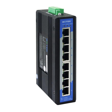
UT-6408W
8-Port 100M Unmanged Ethernet Switch
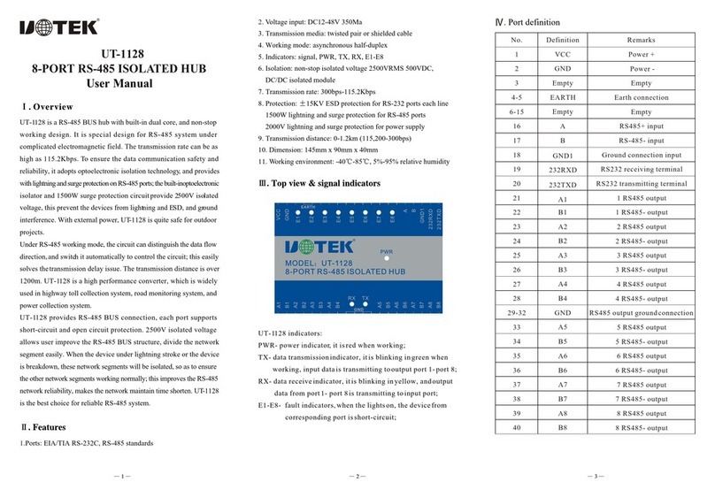
User manual
Ⅰ. Overview
UT-6408W is a 8-port industrial grade unmanaged Ethernet switch
with reverse polarity protection of AC or DC input for avoiding being
damaged. It has ingenious appearance design and supports industrial
standard DIN-Rail and wall-mounted installation, so it's very easy to be
installed and used in any industrial networks.
Ⅱ.Main features
Standards:
Ports
RJ-45 ports: 8x 10/100BaseT(X) ports, auto detection, auto
MDI/MDI-X
LED indicators: PWR, 1~5 RJ-45 ports indicators
Power requirements:
Voltage input: 12/24/48VDC(10.8~52.8VDC)
Power consumption: 120mA@24Vmax
Terminal block: 1x6-pin, pluggable
Overload protection: Yes
Reverse polarity protection: Yes
Characteristics:
IP rating: IP30
Installation: DIN-Rail/wall-mounted
Environment:
Operating temperature:
Storage temperature:
Relative humidity: 0%~95%(non-condensing)
Industrial standards
IEEE 802.3 10BaseT
IEEE 802.3u 100BaseT(X) and 100Base FX
:
-40℃~85℃
-40℃~85℃
:
EMI:FCC Part 15 Subpart B classA,EN55022 class A
EMS:
IEC(EN)61000-4-2(ESD)
IEC(EN)61000-4-3(RS)
IEC(EN)61000-4-4(EFT)
IEC(EN)61000-4-5(Surge)
IEC(EN)61000-4-6(CS)
IEC(EN)61000-4-8
IEC 60068-2-27(Shock)
IEC 60068-2-32(Freefall)
IEC 60068-2-6(Vibration)
Ⅲ. Indicator
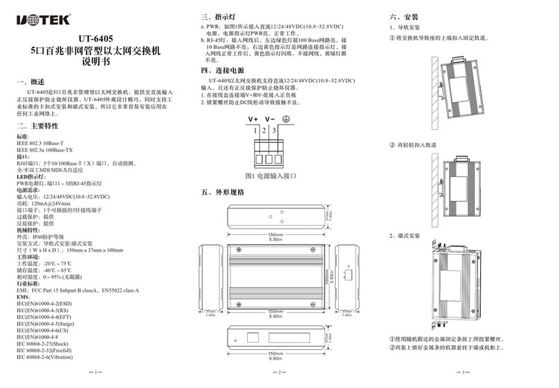
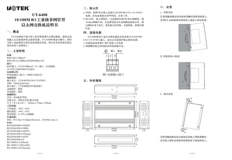
a. PWR1, PWR2 indicators on means power is in normal condition
b. FAIL: When the indicator on, it means the power is break down,
or without power connection
c. RJ-45: When network cable is connected, the green indicator on
the left is on when connected with 100Base, it will not on when
connected with 10Base network; the yellow indicator on the right
is network indication, it will flicker when internet access; the
yellow and green indicator will not on if without internet access
1 2
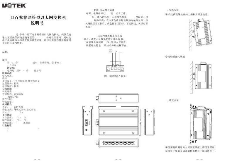
Ⅳ.Power supply connection
UT-6408W series industrial grade Ethernet switch supports
12/24/48VDC(10.8~52.8VDC) input, and the reverse polarity
protection enables it from damage.
1.Connect the positive/negative polarity to V+ and V- terminals
respectively
2. Tighten the screws to avoid loose connection and bad contact.
Figure 1 Power input terminal
Ⅴ. Dimension
Ⅵ. Installation
1. DIN-Rail
① Push the top of the device rail to fixed rail.
② Then push it into the rail slightly again
2.Wall-mounted
①.Tighten the metal fixation strip by screws as shown in the
above figure.
②.Then hang the machine with locked metal strip onto wall or
machine cabinet.
3
V2- V2+ V1- V1+


