Votex 2K0 017 221 User manual

Änderungen des Lieferumfanges
vorbehalten.
Equipment supplied is subject to
alteration.
Modifications de l’ensemble de
livraision réservées.
Ci riserviamo modifiche all’entità
della fornitura.
Ändringar av
leveransomfattningen
förbehålles.
Wijzgingen in leveringsomvang
voorbehouden.
Se reservan las modificaciones
del conjunto de suministro.
Zmeny v dodávkàch vyhrazeny.
Montageanleitung
Fitting instructions
Instructions de montage
Istruzioni di montaggio
Monteringsanvising
Montage-aanwijzing
Instrucciones de montaje
Montázní návod
Distributed by Votex GmbH Printed in Germany by Votex GmbH
Zubehör für Volkswagen/Audi
Accessories for Volkswagen/Audi
Accessoires pour Volkswagen/Audi
1
BA
3
4
2
5
9
10
8
6
7
1
11
12.12.03
Caddy 2004 ⇒
Stückliste
Pos. Bezeichnung Stück
(1) Trenngitter 1
(2) Sterngriffmutter M8 geschlossen 2
(3) Unterlegscheibe 2
(4) Gegenplatte 2
(5) Schlossschraube M8 x 20 2
(6) Gewindehaken 2
Montage hinter der Rücksitzbank (A) 2K0 017 221
2K0 017 221 2K0 017 222
Stückliste
Pos. Bezeichnung Stück
(7) Sterngriffmutter M8 offen 2
(8) Schlossschraube M8 x 45 2
(9) Ankerplatte 2
(10) Kunststoffkappe 4
(11 ) Sterngriffmutter M8 (klein) 2

Distributed by Votex GmbH Printed in Germany by Votex GmbH
2
10
A1
1
A
B
10
6
7
6
2
1
A9 8
- Stecken Sie die Kunststoffkappen -10- auf die offenen
Rohrenden -A- des Trenngitters -1-.
- Klappen Sie die Rücksitzbank nach vorn.
- Stellen Sie das Trenngitter -1- mit Hilfe einer zweiten Person
in den Innenraum des Fahrzeuges.
- Richten Sie die Kunststoffkappen -10- an der Säule C -B- aus.
- Stecken Sie den Gewindehaken -6- links und rechts zwischen
Säule C -B- und der Sicherheitsgurtbefestigung -A-.
- Schrauben Sie die Sterngriffmuttern M8 (offen) -7- auf die
Gewindehaken -6-.
- Drehen Sie die Sterngriffmuttern M8 (offen) -7- soweit auf
den Gewindehaken -6-, bis die Kunststoffkappen -10- an der
Säule C -B- spielfrei anliegen.
Achtung:
Achten Sie darauf das sich der Sicherheitsgurt nicht mit dem
Gewindehaken -6- verklemmt.
- Klappen Sie die Halteösen -A- links und rechts nach oben.
- Stecken Sie die Ankerplatten -9- auf den Halteösen-A-.
- Befestigen Sie die Ankerplatten -9- mit den Schlossschrauben
(M8 x 45) -8- und den Sterngriffmuttern M8 (geschlossen) -2-
mit dem Trenngitter -1-.

Distributed by Votex GmbH Printed in Germany by Votex GmbH
3
A5
94
11
3
3
4
1
2
5
7
8
6
9
10
- Stecken Sie die Schlossschraube (M8 x 20) -5- durch die
Gegenplatte -4-, Halteöse -A- und Ankerplatte -9-.
- Schrauben Sie die Sterngriffmutter M8 (klein) -11- mit der
Unterlegscheibe -3- auf die Schlossschraube (M8 x 20) -5-.
- Richten Sie das Trenngitter aus und ziehen Sie alle
Sterngriffmuttern fest.
- Klappen Sie die Rücksitzbank nach hinten und verriegeln Sie
die Sitzlehnen.
Hinweise:
●Sichern Sie schweres Ladegut zusätzlich mit Spanngurten!
●Das Trenngitter darf nur in Verbindung mit eingesteckten
Kopfstützen in den Rücksitz- Rückenlehnen und verriegelter
Rückenlehne genutzt werden.
●Kontrollieren Sie nach kurzer Fahrstrecke alle Verschraubungen
und ziehen sie ggf. nach.
●Kontrollieren Sie in angemessenen Abständen erneut die
Verschraubungen.
Achtung:
Der Transport von Personen hinter dem Trenngitter ist verboten!!
Montage hinter der Rücksitzbank mit Trenngitterteilung (B) 2K0 017 222
Stückliste
Pos. Bezeichnung Stück
(1) Trenngitter 1
(2) Sterngriffmutter M8 offen 1
(3) Haltestrebe 1
(4) Schlossschraube M8 x 20 1
(5) Gegenplatte 1
(6) Unterlegscheibe 4
Stückliste
Pos. Bezeichnung Stück
(7) Sterngriffmutter M8 geschlossen 1
(8) Gummiauflage 4
(9) Untere Abstützung 1
(10) Sterngriffschraube M8 3

Distributed by Votex GmbH Printed in Germany by Votex GmbH
4
8
9
A
8
9
2
3
A
- Montieren Sie das Trenngitter (A) (2K0 017 221 ) hinter der
Rücksitzbank ein.
- Drücken Sie die Gummiauflagen -8- in der unteren
Abstützung -9- und der oberen Abstützung -A- ein.
- Stecken Sie die Haltestrebe -3- auf die untere Abstützung -9-.
- Schrauben Sie die Sterngriffmutter M8 (offen) -2- ca. 25mm
auf die untere Abstützung -9-.
- Schrauben Sie die untere Abstützung an das Trenngitter.
- Heben Sie das Trenngitter in den Innenraum.
- Um Beschädigungen zu vermeiden und zum Ausrichten des
Trenngitters muss der Knopf -A- in Pfeilrichtung gezogen
werden.

Distributed by Votex GmbH Printed in Germany by Votex GmbH
5
A
35
4
6
7
6
10
2
9
A
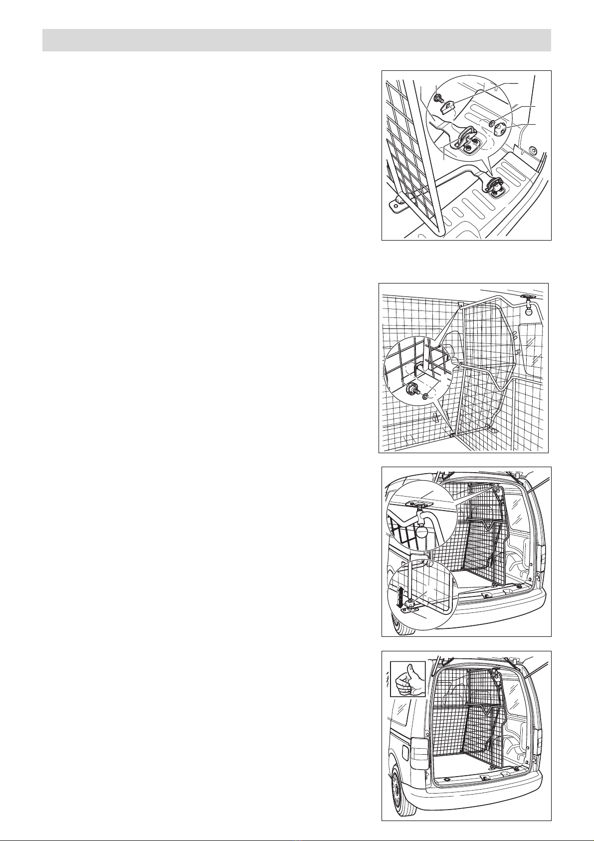
●Durch drehen der unteren Abstützung -9- wird der
Anpressdruck an der oberen Abstützung -A- eingestellt.
- Drehen Sie die untere Abstützung -9- soweit hinein oder
heraus bis die obere Abstützung -A- an dem Dachquerträger
fest anliegt.
- Drehen Sie die Sterngriffmutter -2- gegen das Trenngitter.
- Drehen Sie alle Sterngriffschrauben und -muttern fest.
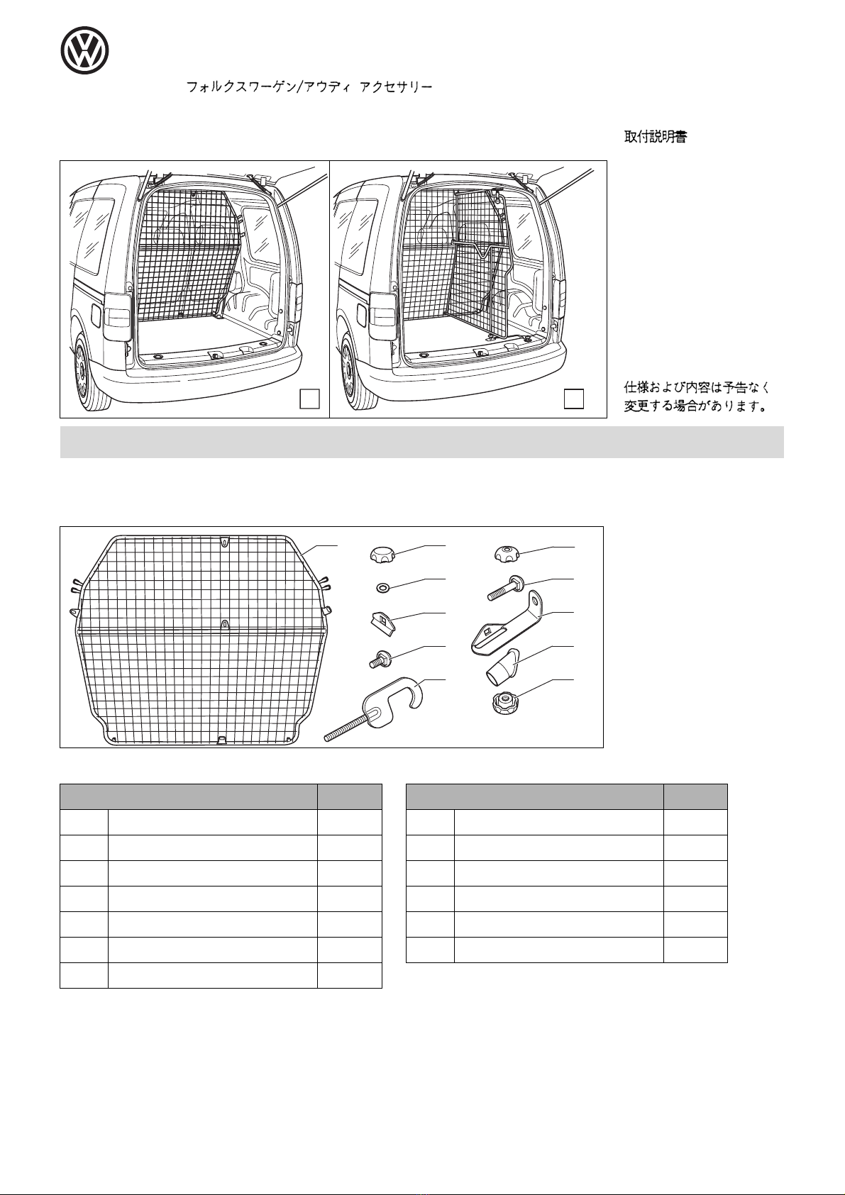
Hinweise:
●Sichern Sie schweres Ladegut zusätzlich mit Spanngurten!
●Das Trenngitter darf nur in Verbindung mit eingesteckten Kopfstützen in
den Rücksitz- Rückenlehnen und verriegelter Rückenlehne genutzt
werden.
●Kontrollieren Sie nach kurzer Fahrstrecke alle Verschraubungen und
ziehen sie ggf. nach.
●Kontrollieren Sie in angemessenen Abständen erneut die
Verschraubungen.
Achtung:
Der Transport von Personen hinter dem Trenngitter ist verboten!!
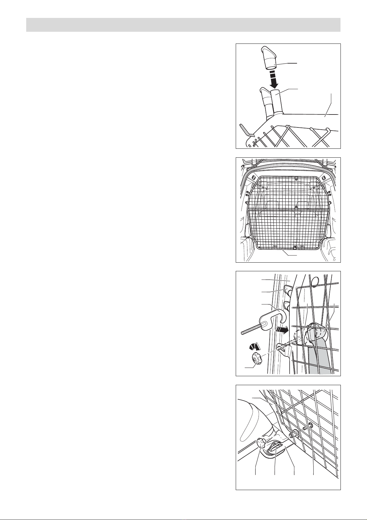
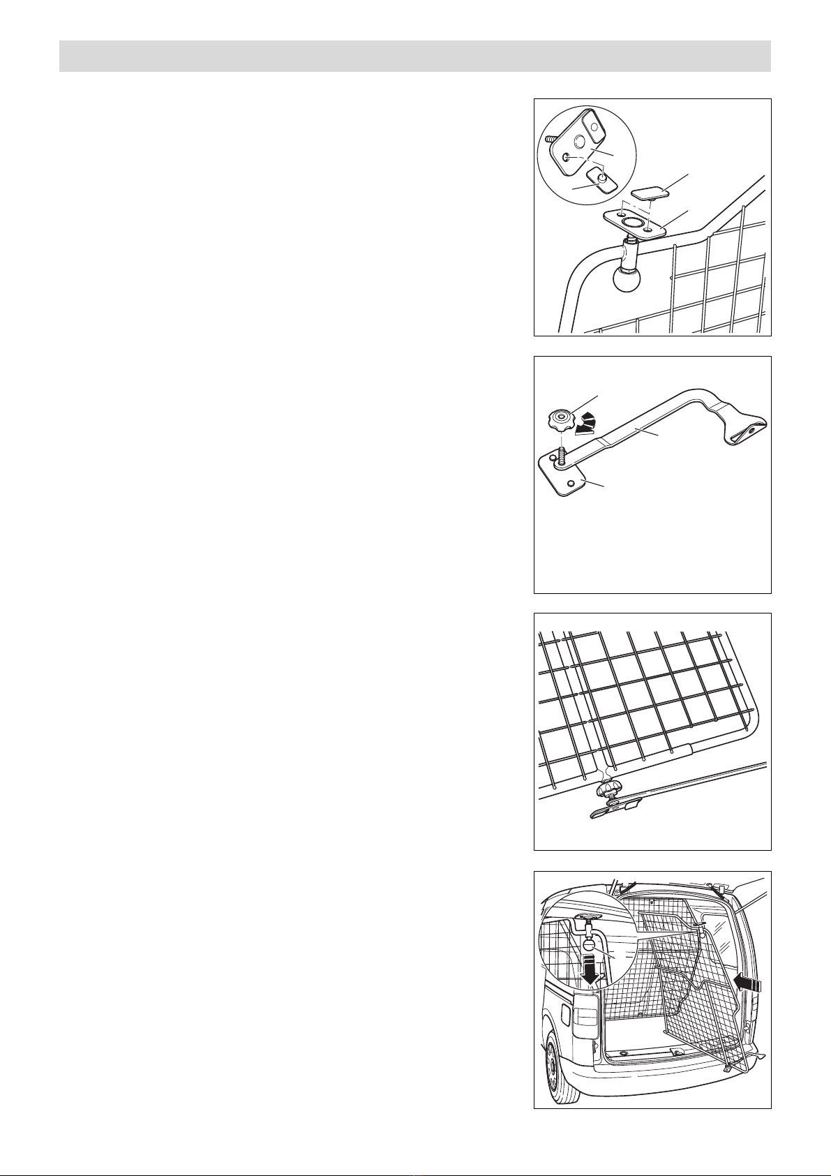
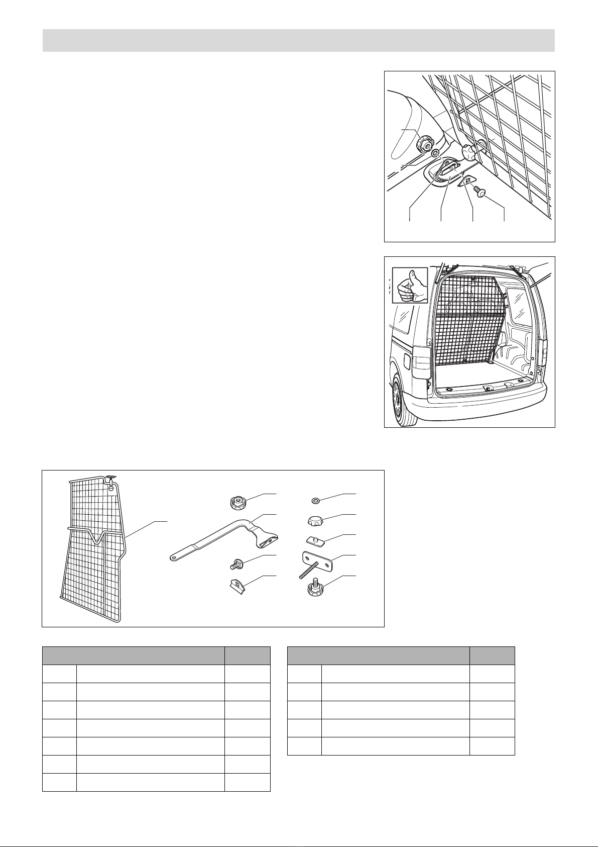
- Drehen Sie die Sterngriffschraube -10- mit der
Unterlegscheibe -6- in das Trenngitter -1-.
- Klappen Sie die Halteöse -A- nach oben.
- Führen Sie die Haltestrebe -3- auf die Halteöse -A-.
- Stecken Sie die Schlossschraube (M8 x 20) -4- durch die
Gegenplatte -5-, Halteöse -A- und Haltestrebe -3-.
- Schrauben Sie die Sterngriffmutter -7- mit der
Unterlegscheibe -6- auf die Schlossschraube (M8 x 20) -4-.

Änderungen des Lieferumfanges
vorbehalten.
Equipment supplied is subject to
alteration.
Modifications de l’ensemble de
livraision réservées.
Ci riserviamo modifiche all’entità
della fornitura.
Ändringar av
leveransomfattningen
förbehålles.
Wijzgingen in leveringsomvang
voorbehouden.
Se reservan las modificaciones
del conjunto de suministro.
Zmeny v dodávkàch vyhrazeny.
Montageanleitung
Fitting instructions
Instructions de montage
Istruzioni di montaggio
Monteringsanvising
Montage-aanwijzing
Instrucciones de montaje
Montázní návod
Distributed by Votex GmbH Printed in Germany by Votex GmbH
Zubehör für Volkswagen/Audi
Accessories for Volkswagen/Audi
Accessoires pour Volkswagen/Audi
1
BA
3
4
2
5
9
10
8
6
7
1
11
12.12.03
Caddy 2004 ⇒
List of parts
Item Designation Quantity
(1) Separating grid 1
(2) Star grip nut M8 closed 2
(3) Plain washer 2
(4) Counter plate 2
(5) Coach bolt M8 x 20 2
(6) Threaded bracket 2
Assembly behind the rear seat (A) 2K0 017 221
2K0 017 221 2K0 017 222
List of parts
Item Designation Quantity
(7) Star grip nut M8 open 2
(8) Coach bolt M8 x 45 2
(9) Anchor plate 2
(10) Plastic cap 4
(11 ) Star grip nut M8 (small) 2

Distributed by Votex GmbH Printed in Germany by Votex GmbH
2
10
A1
1
A
B
10
6
7
6
2
1
A9 8
- Connect plastic caps -10- to the open tube ends -A- of the
separating grid -1-.
- Fold rear seat bench forwards.
- Place the separating grid -1- in the vehicle interior with a
second person.
- Align the plastic caps -10- on the C-pillar -B-.
- Place the threaded bracket -6- on the left and right side
between the C-pillar -B- and the seat belt locking -A-.
- Fit the star grip nuts M8 (open) -7- to the threaded brackets -
6-.
- Screw the star grip nuts M8 (open) -7- on the threaded
bracket -6- until the plastic caps -10- are laying on the C-
pillar -B- without a play.
Warning:
Observe that the seat belt does not jam with the threaded bracket -
6-.
- Fold the left and right retaining eyes -A- upwards.
- Place the anchor plates -9- on the retaining eyes -A-.
- Secure the anchor plates -9- with the coach bolts (M8 x 45) -8-
and the star grip nuts M8 (closed) -2- to the separating grip -1-.

Distributed by Votex GmbH Printed in Germany by Votex GmbH
3
A5
94
11
3
3
4
1
2
5
7
8
6
9
10
- Pass the coach bolt (M8 x 20) -5- through the counterplate -
4-, the retaining eye -A- and the anchor plate -9-.
- Fit the star grip nut M8 (small) -11- with washer -3- on the
coach bolt (M8 x 20) -5-.
- Align the separating grid and tighten all star grip nuts.t.
- Fold the rear seat backwards and lock the seat backrests.
Notes:
●Secure heavy load additionally with tensioning belts.
●The separating grid must only be used in connection with head
restraints inserted in the rear seat back of a seat and locked
back of a seat.
●Check all threaded joints after a brief drive and retighten, if
necessary.
●Check threaded joints regularly.
Warning:
It is not allowed to transport persons behind the separating grid.
Assembly behind the rear seat with the separating grid division (B) 2K0 017 222
List of parts
Item Designation Quantity
(1) Separating grid 1
(2) Star grip nut M8 open 1
(3) Retainer support 1
(4) Coach bolt M8 x 20 1
(5) Counter plate 1
(6) Plain washer 4
List of parts
Item Designation Quantity
(7) Star grip nut M8 closed 1
(8) Rubber support 4
(9) Lower support 1
(10) Star grip bolt M8 3

Distributed by Votex GmbH Printed in Germany by Votex GmbH
4
8
9
A
8
9
2
3
A
- Install the separating grid (A) (2K0 017 221 ) behind the rear
seat.
- Push rubber supports -8- in the lower support -9- and the
upper support -A- in.
- Fit retainer support -3- to lower support -9-.
- Fit the star grip nut M8 (open) -2- approx. 25 mm to the lower
support -9-.
- Fit the lower support to the separating grid.
- Lift the separating grid in the interior.
- To avoid damages and to align the separating grid the head -
A- must be pulled in direction of arrow.

Distributed by Votex GmbH Printed in Germany by Votex GmbH
5
A
35
4
6
7
6
10
2
9
A
●The pressure at the upper support -A- is adjusted by turning
the lower support -9-.
- Turn the lower support -9- in or out until the upper support -A-
lies tightly against the roof cross member.
- Turn the star grip nut -2- against the separating grip.
- Tighten all star grip bolts and nuts.
Notes:
●Secure heavy load additionally with tensioning belts.
●The separating grid must only be used in connection with head restraints
inserted in the rear seat back of a seat and locked back of a seat.
●Check all threaded joints after a brief drive and retighten, if necessary.
●Check threaded joints regularly.
Warning:
It is not allowed to transport persons behind the separating grid.
- Fit the star grip bolt -10- on the separating grid -1- with plain
washer -6-.
- Fold the retaining eye -A- upwards.
- Place the retainer support -3- on the retaining eye -A-.
- Pass the coach bolt (M8 x 20) -4- through the counterplate -
5-, the retaining eye -A- and the support -3-.
- Fit the star grip nut -7- on the coach bolt (M8 x 20) -4- with
washer -6-.

Änderungen des Lieferumfanges
vorbehalten.
Equipment supplied is subject to
alteration.
Modifications de l’ensemble de
livraision réservées.
Ci riserviamo modifiche all’entità
della fornitura.
Ändringar av
leveransomfattningen
förbehålles.
Wijzgingen in leveringsomvang
voorbehouden.
Se reservan las modificaciones
del conjunto de suministro.
Zmeny v dodávkàch vyhrazeny.
Montageanleitung
Fitting instructions
Instructions de montage
Istruzioni di montaggio
Monteringsanvising
Montage-aanwijzing
Instrucciones de montaje
Montázní návod
Distributed by Votex GmbH Printed in Germany by Votex GmbH
Zubehör für Volkswagen/Audi
Accessories for Volkswagen/Audi
Accessoires pour Volkswagen/Audi
1
BA
3
4
2
5
9
10
8
6
7
1
11
12.12.03
Caddy 2004 ⇒
Liste des pièces détachées
Repère Désignation Nombre
(1) Grille de séparation 1
(2) Ecrou à poignée étoilée M8 fermé 2
(3) Rondelle entretoise 2
(4) Plaque de renfort 2
(5) Vis de fermeture M8 x 20 2
(6) Crochet fileté 2
Montage derrière la banquette arrière (A) 2K0 017 221
2K0 017 221 2K0 017 222
Liste des pièces détachées
Repère Désignation Nombre
(7) Ecrou à poignée étoilée M8 ouvert 2
(8) Vis de fermeture M8 x 45 2
(9) Plaque d'ancrage 2
(10) Capuchon en matière plastique 4
(11 ) Ecrou à poignée étoilée M8 (petit) 2

Distributed by Votex GmbH Printed in Germany by Votex GmbH
2
10
A1
1
A
B
10
6
7
6
2
1
A9 8
- Enfoncez les capuchons en matière plastique -10- sur les bouts
de tube ouverts -A- de la grille de séparation -1-.
- Rabattre la banquette arrière vers l'avant.
- Mettez en place la grille de séparation -1- dans l'habitacle
du véhicule avec l'aide d'un deuxième mécanicien.
- Ajustez les capuchons en matière plastique -10- au montant
C -B-.
- Introduisez les crochets filetés -6- gauche et droit entre le
montant C -B- et la fixation de la ceinture de sécurité -A-.
- Vissez les écrous à poignée étoilée M8 (ouverts) -7- sur les
crochets filetés -6-.
- Vissez les écrous à poignée étoilée M8 (ouverts) -7- sur les
crochets filetés -6- jusqu'à ce que les capuchons en matière
plastique -10- reposent sans jeu sur le montant C -B-.
Attention :
Veillez à ce que la ceinture de sécurité et le crochet fileté -6- ne
coincent pas entre eux.
- Rabattez les œillets de retenue -A- gauche et droit vers le
haut.
- Placez les plaques d'ancrage -9- sur les œillets de retenue -A-.
- Fixez les plaques d'ancrage -9- à la grille de séparation -1- à
l'aide des vis de fermeture (M8 x 45) -8- et des écrous à
poignée étoilée M8 (fermés) -2-.

Distributed by Votex GmbH Printed in Germany by Votex GmbH
3
A5
94
11
3
3
4
1
2
5
7
8
6
9
10
- Passez la vis de fermeture (M8 x 20) -5- par la plaque de
renfort -4-, l'œillet de retenue -A- et la plaque d'ancrage -9-.
- Vissez l'écrou à poignée étoilée M8 (petit) -11- muni de la
rondelle entretoise -3- sur la vis de fermeture (M8 x 20) -5-.
- Dégauchissez la grille de séparation et serrez tous les écrous
à poignée étoilée.
- Rabattez la banquette arrière vers l'arrière et verrouillez les
dossiers de siège.
Remarques :
●Freinez tout matériau transporté à poids lourd à l'aide de sangles de
serrage !
●Si vous vous servez de la grille de séparation, il faut que les appuis-tête
soient enfoncés dans les dossiers des sièges arrière et que ces dossiers
soient verrouillés.
●Au bout d'un trajet court, contrôlez tous les vissages et, si nécessaire,
resserrez-les.
●Au bout d'intervalles à durée adéquate, veuillez contrôler de nouveau ces
vissages.
Attention :
Il est strictement interdit de transporter des personnes assises derrière la
grille !!
Montage derrière la banquette arrière avec partage de la grille de séparation (B) 2K0 017 222
Liste des pièces détachées
Repère Désignation Nombre
(1) Grille de séparation 1
(2) Ecrou à poignée étoilée M8 ouvert 1
(3) Tirant de maintien 1
(4) Vis de fermeture M8 x 20 1
(5) Plaque de renfort 1
(6) Rondelle entretoise 4
Liste des pièces détachées
Repère Désignation Nombre
(7) Ecrou à poignée étoilée M8 fermé 1
(8) Embase de caoutchouc 4
(9) Appui inférieur 1
(10) Vis à poignée étoilée M8 3

Distributed by Votex GmbH Printed in Germany by Votex GmbH
4
8
9
A
8
9
2
3
A
- Montez la grille de séparation (A) (2K0 017 221 ) derrière la
banquette arrière.
- Enfoncez les embases de caoutchouc -8- dans les appuis
inférieur -9- et supérieur -A-.
- Attachez le tirant de maintien -3- à l'appui inférieur -9-.
- Vissez l'écrou à poignée étoilée M8 (ouvert) -2- (env. 25 mm)
sur l'appui inférieur -9-.
- Vissez l'appui inférieur à la grille de séparation.
- Placez la grille de séparation dans l'habitacle.
- Pour éviter tout endommagement et pour dégauchir la grille
de séparation, il faut tirer le bouton -A- dans le sens de la
flèche.

Distributed by Votex GmbH Printed in Germany by Votex GmbH
5
A
35
4
6
7
6
10
2
9
A
●C'est en tournant l'appui inférieur -9- que s'ajuste la pression
appliquée à l'appui supérieur -A-.
- Serrez ou desserrez l'appui inférieur -9- jusqu'à ce que l'appui
supérieur -A- s'appuie bien contre la traverse du pavillon.
- Serrez l'écrou à poignée étoilée -2- contre la grille de
séparation.
- Serrez tous les écrous et vis à poignée étoilée.
Remarques :
●Freinez tout matériau transporté à poids lourd à l'aide de sangles de
serrage !
●Si vous vous servez de la grille de séparation, il faut que les appuis-tête
soient enfoncés dans les dossiers des sièges arrière et que ces dossiers
soient verrouillés.
●Au bout d'un trajet court, contrôlez tous les vissages et, si nécessaire,
resserrez-les.
●Au bout d'intervalles à durée adéquate, veuillez contrôler de nouveau
ces vissages.
Attention :
Il est strictement interdit de transporter des personnes assises derrière la
grille !!
- Munie de la rondelle entretoise -6-, vissez la vis à poignée
étoilée -10- dans la grille de séparation -1-.
- Rabattez l'œillet de retenue -A- vers le haut.
- Guidez le tirant de maintien -3- sur l'œillet de retenue -A-.
- Passez la vis de fermeture (M8 x 20) -4- par la plaque de
renfort -5-, l'œillet de retenue -A- et le tirant de maintien -3-.
- Vissez l'écrou à poignée étoilée -7- muni de la rondelle
entretoise -6- sur la vis de fermeture (M8 x 20) -4-.

Änderungen des Lieferumfanges
vorbehalten.
Equipment supplied is subject to
alteration.
Modifications de l’ensemble de
livraision réservées.
Ci riserviamo modifiche all’entità
della fornitura.
Ändringar av
leveransomfattningen
förbehålles.
Wijzgingen in leveringsomvang
voorbehouden.
Se reservan las modificaciones
del conjunto de suministro.
Zmeny v dodávkàch vyhrazeny.
Montageanleitung
Fitting instructions
Instructions de montage
Istruzioni di montaggio
Monteringsanvising
Montage-aanwijzing
Instrucciones de montaje
Montázní návod
Distributed by Votex GmbH Printed in Germany by Votex GmbH
Zubehör für Volkswagen/Audi
Accessories for Volkswagen/Audi
Accessoires pour Volkswagen/Audi
1
BA
3
4
2
5
9
10
8
6
7
1
11
12.12.03
Caddy 2004 ⇒
Distinta dei pezzi
Pos. Denominazione pezzi
(1) Griglia di separazione 1
(2) Dado con manopola a crociera M8 chiuso 2
(3) Rondella spessore 2
(4) Contropiastra 2
(5) Vite a testa quadra M8 x 20 2
(6) Gancio filettato 2
Montaggio dietro i sedili posteriori (A) 2K0 017 221
2K0 017 221 2K0 017 222
Distinta dei pezzi
Pos. Denominazione pezzi
(7) Dado con manopola a crociera M8 aperto 2
(8) Vite a testa quadra M8 x 45 2
(9) Piastra di ancoraggio 2
(10) Cappuccio in plastica 4
(11 ) Dado con manopola a crociera M8
(piccolo)
2

Distributed by Votex GmbH Printed in Germany by Votex GmbH
2
10
A1
1
A
B
10
6
7
6
2
1
A9 8
- Attaccare i cappucci in plastica -10- alle estremità aperte dei
tubi -A- della griglia di separazione -1-.
- Ripiegare in avanti il divano posteriore.
- Sistemare la griglia di separazione -1- con l'aiuto di una
seconda persona nell'abitacolo del veicolo.
- Allineare i cappucci in plastica -10- sul montante C -B-.
- Inserire il gancio filettato -6- a sinistra ed a destra tra il
montante C -B- ed il fissaggio della cintura di sicurezza -A-.
- Avvitare i dadi con manopola a crociera M8 (aperti) -7- sui
ganci filettati -6-.
- Avvitare i dadi con manopola a crociera M8 (aperti) -7- sul
gancio filettato -6- finché i cappucci in plastica -10- non
arrivano a poggiare senza gioco sul montante C -B-.
Attenzione:
Aver cura che la cintura di sicurezza non s'incastri nel gancio
filettato -6-.
- Ribaltare in alto le staffe di sostegno -A- a sinistra ed a destra.
- Attaccare le piastre di ancoraggio -9- alle staffe di ritegno -A-.
- Fissare le piastre di ancoraggio -9- con le viti a testa quadra
(M8 x 45) -8- ed i dadi con manopola a crociera M8 (chiusi) -
2- sulla griglia di separazione -1-.

Distributed by Votex GmbH Printed in Germany by Votex GmbH
3
A5
94
11
3
3
4
1
2
5
7
8
6
9
10
- Far passare la vite a testa quadra (M8 x 20) -5- attraverso la
contropiastra -4-, la staffa di ritegno -A- e la piastra di
ancoraggio -9-.
- Avvitare il dado con manopola a crociera M8 (piccolo) -11-
con la rondella -3- sulla vite a testa quadra (M8 x 20) -5-.
- Allineare la griglia di separazione ed avvitare tutti i dadi con
manopola a crociera.
- Ribaltare i sedili posteriori indietro e bloccare gli schienali.
Avvertenze:
●Assicurare i carichi pesanti addizionalmente con cinghie di
fissaggio!
●La griglia di separazione deve essere usata unicamente con i
poggiatesta inseriti negli schienali dei sedili posteriori e con lo
schienale bloccato.
●Dopo un breve percorso controllare tutti i collegamenti a vite ed
eventualmente riserrare le viti.
●Ricontrollare i collegamenti a vite ad intervalli regolari.
Attenzione:
E' vietato il trasporto di persone dietro la griglia di separazione!!
Montaggio dietro i sedili posteriori con griglia di separazione divisa (B) 2K0 017 222
Distinta dei pezzi
Pos. Denominazione pezzi
(1) Griglia di separazione 1
(2) Dado con manopola a crociera M8 aperto 1
(3) Cantonale di sostegno 1
(4) Vite a testa quadra M8 x 20 1
(5) Contropiastra 1
(6) Rondella spessore 4
Distinta dei pezzi
Pos. Denominazione pezzi
(7) Dado con manopola a crociera M8 chiuso 1
(8) Supporto in gomma 4
(9) Sostegno inferiore 1
(10) Vite con manopola a crociera M8 3

Distributed by Votex GmbH Printed in Germany by Votex GmbH
4
8
9
A
8
9
2
3
A
- Montare la griglia di separazione (A) (2K0 017 221 ) dietro i
sedili posteriori.
- Inserire i supporti in gomma -8- premendoli nel sostegno
inferiore -9- ed in quello superiore -A-.
- Applicare il cantonale di sostegno -3- sul sostegno inferiore -
9-.
- Avvitare il dado con manopola a crociera M8 (aperto) -2- di
circa 25 mm sul sostegno inferiore -9-.
- Avvitare il sostegno inferiore sulla griglia di separazione.
- Sollevare la griglia di separazione e sistemarla nell'abitacolo.
- A scanso di danneggiamenti e per allineare la griglia di
separazione, tirare il bottone -A- nella direzione indicata
dalla freccia.

Distributed by Votex GmbH Printed in Germany by Votex GmbH
5
A
35
4
6
7
6
10
2
9
A
●Girando il sostegno inferiore -9- si regola la pressione di
appoggio del sostegno superiore -A-.
- Avvitare ovvero svitare il sostegno inferiore -9- finché il
sostegno superiore -A- non si appoggia saldamente sulla
traversa del tetto.
- Avvitare il dado con manopola a crociera -2- contro la griglia
di separazione.
- Serrare tutte le viti ed i dadi con manopola a crociera.
Avvertenze:
●Assicurare i carichi pesanti addizionalmente con cinghie di fissaggio!
●La griglia di separazione deve essere usata unicamente con i
poggiatesta inseriti negli schienali dei sedili posteriori e con lo schienale
bloccato.
●Dopo un breve percorso controllare tutti i collegamenti a vite ed
eventualmente riserrare le viti.
●Ricontrollare i collegamenti a vite ad intervalli regolari.
Attenzione:
E' vietato il trasporto di persone dietro la griglia di separazione!!
- Avvitare la vite con manopola a crociera -10- con la rondella
-6- nella griglia di separazione -1-.
- Ribaltare in alto la staffa di sostegno -A-.
- Guidare il cantonale di sostegno -3- sulla staffa di ritegno -
A-.
- Far passare la vite a testa quadra (M8 x 20) -4- attraverso la
contropiastra -5-, la staffa di ritegno -A- ed il cantonale di
sostegno -3-.
- Avvitare il dado con manopola a crociera -7- con la rondella
-6- sulla vite a testa quadra (M8 x 20) -4-.
This manual suits for next models
1
Table of contents
Languages: