Votronic VCC 1212-20 C User manual

Installation and Operating Manual
Fully automatic charging converter (booster), B2B Battery to Battery charger for optimum
charging of the battery in the living area during driving. Designed for operation at a 13-pole
trailer connector for caravan and living compartments.
VCC 1212-20 C Input 12 V / max. 20 A Output 12 V / max. 24 A No. 3321
Please read these mounting instructions and the operating manual completely and
attentively.
Particularly observe page 11 "Safety Regulations and Appropriate Application",
prior to starting connection and start-up.
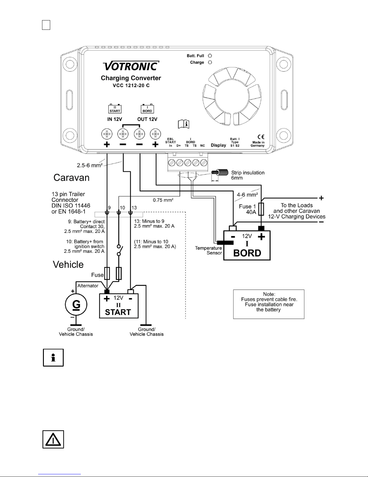
The unit is primarily designed for operation at the 13-pole trailer connector of the towing vehicle for charging of the
caravan battery. Its automatic control ensures, that the rating of the connector and the vehicle's electric system in front of
it (12 V / max. 20 Amperes) will not be exceeded. The efficiency of the unit results from this aspect.
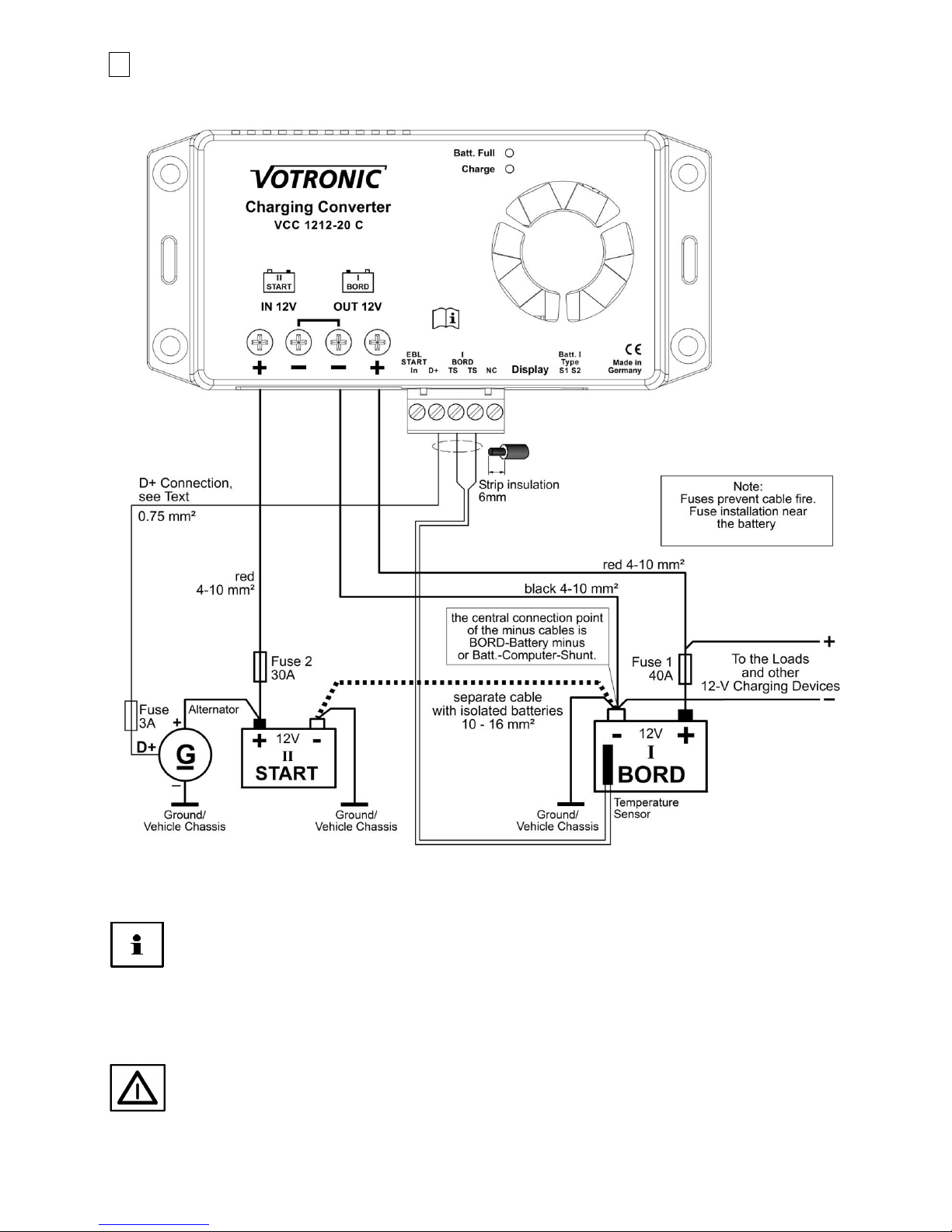
The unit is installed in the caravan, in the living compartment. It supplies the optimum charging voltage for the battery -
independently of the vehicle's board voltage fluctuations or voltage losses of cables/connectors.
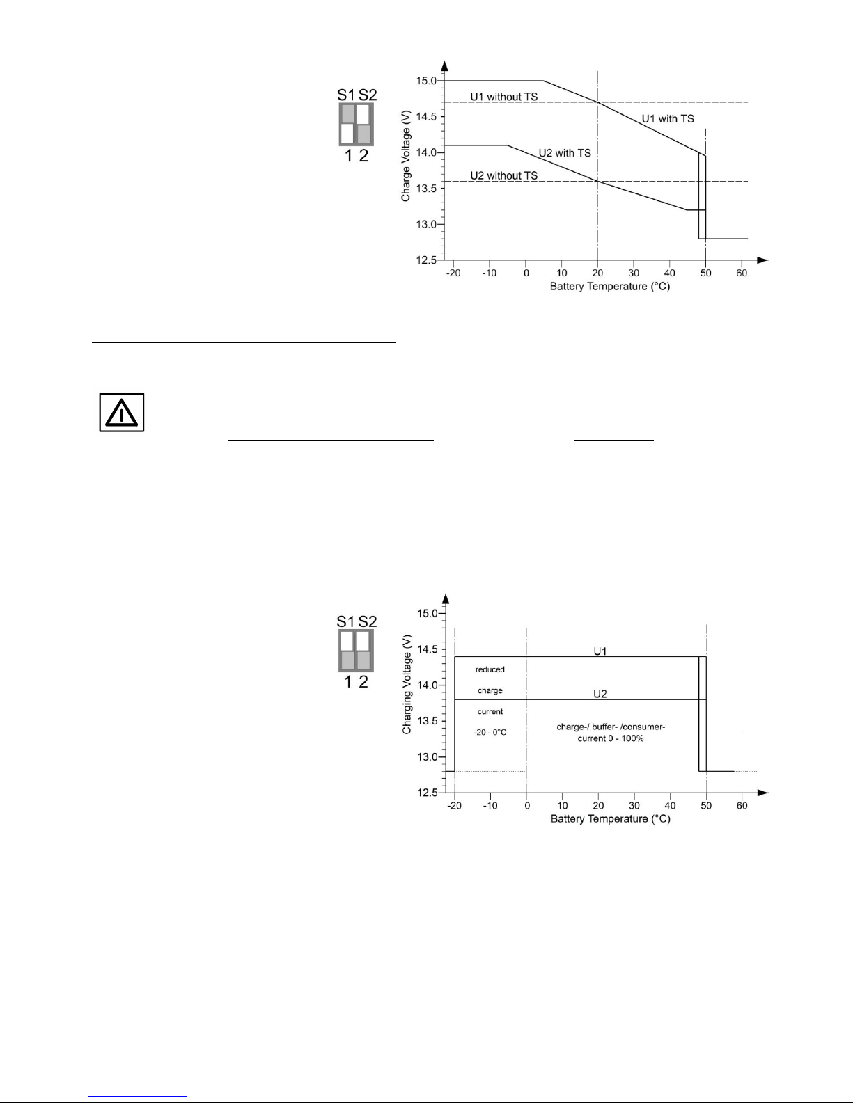
This is realized by 4adjustable charging programs IU1oU2 for conventional lead-acid, gel, AGM batteries or advanced
Lithium LiFePO4 supply batteries. They allow unattended, quick and gentle full charging from any charging state with
subsequent trickle charging.
Depending on the driving condition, the voltage of modern EURO standard 6, 6 + plus- vehicles with energy-saving,
intelligent generators fluctuates considerably (12.6 V … 15.5 V). These fluctuations are now completely equalized by the
charging converter to ensure uniform charging of the BOARD battery and protection of the 12 V consumers, which are
connected to that battery.
Due to the higher charging current rates, which are now possible, shorter charging times and fully charged batteries are
achieved, even with conventional generators and long connection cables.
The efficient charging converter ensures high charging capacity, already within short distances.
Full charging when driving longer distances.
It increases or reduces the voltage to the level, which is required for precise charging of the BOARD battery for the
living room with the optimum charging characteristic line.
The charging converter excels by its compact design, low weight (high-frequency switch mode boost and buck
converter technology) and powerfully dimensioned power components for safe operation.
The simultaneously supplied 12 V consumer loads are protected against overvoltage and voltage fluctuations.
The integrated recharging branch 12 V/0 ... 1 A provides charging/trickle charging of the vehicle's 12 V battery in case
of extended standstill periods. It will be activated automatically with external charging of the BOARD battery by means
of a mains supply charger.
Further Characteristics of the Unit:
The charging voltage is free from peaks and is controlled in such a way, that overcharging of the batteries is excluded.
Fully Automatic Operation: The unit is permanently connected to the batteries, and it is automatically activated by the
running generator of the vehicle. Battery discharge in case of an engine stop is avoided.
Charging aid for deeply discharged lead batteries or switched-off LiFePO4 batteries: Gentle preliminary charging of the
(lead-acid, gel, AGM) battery or automatic reactivation of the Li battery, if consumers are possibly still switched-on.
Parallel and Floating Operation: In case of simultaneous consumption, the battery will either continue to be charged or
maintained via trickle charging. Calculation and control of the adaptation of the charging times is effected automatically
by the unit.
Unattended Charging: Multiple protection against overload, overheating, overvoltage, short circuit, incorrect behaviour
and back discharge of the battery by electronically controlled gradual reduction down to separation of unit and battery.
Integrated On-board Mains Suppression Filter: Unproblematic parallel operation of further charging sources (mains
supply chargers, solar systems).
Charging Cable Compensation: Automatic compensation of voltage losses on the charging cables.
Connection for Battery Temperature Sensor (Sensor 825 included in the standard delivery scope):
Lead batteries (acid, gel, AGM): In case of low outside temperatures, full charging of the weak battery is improved by
automatic adaptation of the charging voltage to the battery temperature, and in case of summery temperatures
unnecessary battery gassing and battery load will be avoided.
LiFePO4 Batteries: Battery protection in case of high temperatures and particularly in case of low temperatures
below 0 °C.

--2--
1
Connection Plan for Operation with 13-pole Trailer Connector
for Caravan and Living Compartment Operation:
Always install the unit as close as possible to the BOARD battery.
The configuration of the connector contacts of the trailer might be deviating and must be checked for each
individual case. The drawn configuration of the connector contacts provides the following advantages:
The power for the charging converter is supplied at connector No. 9 (+) and 13 (-), and is switched on or
switched-off by the switched 12 V signal No. 10.
During extended standstill periods and charging of the BOARD battery (mains, solar), the recharging
branch of the VCC 1212-20 C (12 V/0…1 A) can be used for trickle charging of the vehicle's STARTER
battery.
The 12 V heating cartridge of the refrigerator can be connected to the connector No. 10 (+) and 11 (-)
during driving, while the supply of the refrigerator control is taken over by the BOARD battery.
Reverse battery (12 V +/- mix-up) at the large power terminals IN 12 V and OUT 12 V must be avoided
in any case. This will result in serious damage of the unit!
Observe the cross-sections and lengths of the cables.
Insert fuses near the battery for protection of the cables.

--3--
2
General Connection Plan for Operation without Connector,
such as in smaller campers or boats:
Always install the unit as close as possible to the BOARD battery.
Connection "D+": With "D+": Control input for charging converter ON / OFF (preferential).
Without "D+": Charging converter operates voltage-controlled (also refer to
Function Selection, page 5, 2).
During extended standstill periods and charging of the BOARD battery, the recharging branch of the VCC
1212-20 C (12 V/0…1 A) is used for trickle charging of the vehicle's STARTER battery.
Reverse battery (12 V +/- mix-up) at the large power terminals IN 12 V and OUT 12 V must be avoided
in any case. This will result in serious damage of the unit!
Observe the cross-sections and lengths of the cables.
Insert fuses near the battery for protection of the cables.

--4--
1
2
Installation of the Unit
Install the charger near the BOARD battery to be charged (for short charging cables) at a clean, level and hard mounting
surface, which is protected from moisture, humidity and aggressive battery gases. The unit can be installed in any position.
Despite the charger's high efficiency, heat is produced, which is brought out of the casing by means of the built-in fan. The
vent holes of the unit should never be covered (minimum distance 5 cm) to ensure full charging capacity. Ensure sufficient
ventilation in the environment of the unit, so that the heat can be dissipated.
Otherwise, in the event of overheating, the charger will reduce its charging capacity.
Unit Connection
a. Choose the suitable connection plan:
Connection Plan for Operation at the 13-pole Trailer Connector
for Caravan and Living Compartment Operation, page 2.
General Connection Plan for Operation without Connector,
such as in smaller campers or boats, page 3.
b. Establish the power connections at large terminals.
Reverse battery (+/- mix-up) might result in serious damage of the unit!
c. Establish the control connections at the 5-pole terminal strip, i. e.:
Terminal "D+": 1) Connect it: automatic unit control via signal vehicle D+.
2) Not used: automatic unit control via operating voltage.
Further description function selection, see page 2.
Unit Settings
d. Imperatively set the charging program for the "BOARD" battery (type, design, technology acid, gel, AGM,
LiFePO4), from page 8.
Start-up and Function Test
e. Further description, see page 7.
Further operation of the unit is not required during normal automatic mode.
Connection of the 5-pole Plug-in Terminal Strip (Control Connections):
Plug-in Terminal Strip: In case of limited space, the strip can be removed and reinserted at any time for easy cable
connection.
Cable Cross-Sections: 0,75 mm2or more.
Length to be stripped: approx. 6 mm.
Protection: The inputs of this strip are protected against overvoltage and reverse battery.
"TS TS": Measuring input for the temperature of the BOARD supply battery:
Connect the temperature sensor to the terminals "TS - TS" (any polarity). Further details concerning the functions of the
sensor can be found under the paragraph "Battery Temperature Sensor" (page 5) and the charging programs.
If the charging program LiFePO4 had been set: No function of the charging converter without temperature sensor (safety)!
"EBL START In": Connection without function, terminal is left blank.
"NC": Connection without function, terminal is left blank.

--5--
"D+": Control input charging converter ON / OFF and function selection:
Two (2) operating modes for automatic ON / OFF control of the unit are possible:
1) Connection of terminal "D+": Activation of the charging converter by control signal of the vehicle:
This operating mode is to be used for the caravan living compartment via plug connections, for conventional
generators/vehicles, as well as for EURO standard 6, 6+ vehicles with energy management, start/stop, strongly
varying voltages of generator/STARTER batteries during energy recovery etc. Also refer to the connection plan, page 2.
Advantageous for stable operation, even with long cables between STARTER battery and charging converter in
connection with conventional generators.
Increase of the charging capacity *: > 11.70 V
Reduction of the charging capacity *: < 11.40 V
Switching off threshold (with continuous signal "D+") *: < 11.20 V with delay 30 s
Recharging branch for STARTER battery (trickle charging), if the BOARD battery is charged by a mains supply charger: ACTIVE
2) No connection of terminal "D+". It is left blank: Pure voltage control of the charging converter:
The unit is activated by the increased voltage at the STARTER battery due to the running engine. It will be switched off
automatically in case of a voltage drop (engine off).
This operating mode requires powerful, short cables to the STARTER battery and a conventional,
a non-intelligent generator with sufficient high and uniform charging voltage (not Euro 6).
During this operating mode the STARTER battery cannot be discharged, due to the high switching off threshold.
Note:
If voltage had been supplied to the terminal "D+" by mistake, the unit will memorize this "control by signal D+" and will expect this
signal for the further operation.
Reset: Return to the operating mode "Voltage Control" (without "D+") is possible by separating the unit from any
operating voltage for 30 seconds. (Separate BOARD and STARTER battery).
Increase of the charging capacity *: > 13.30 V
Reduction of the charging capacity *: < 13.00 V
Switching off threshold*: < 12.90 V with delay 30 s
Recharging branch for STARTER battery (trickle charging), if the BOARD battery is charged by a mains supply charger: BLOCKED
* Also see "Function of the Power Control at STARTER Battery and Generator", page 7.
Battery Temperature Sensor:
Connect the temperature sensor (included in the standard delivery scope) to the terminals "TS TS" (any polarity).
The temperature sensor controls the temperature of the BOARD supply battery.
Ensure that the installation place of the sensor is not influenced by any source of heat (engine heat, exhaust, heater
etc.)!
Lead-Acid, Gel, AGM Batteries:
Installation: The thermal contact of sensor and battery inside temperature should be well. Thus, it should be screwed
down to the negative pole or positive pole of the battery. It is also possible to fasten it at the sidewall centre of the battery
casing.
Function: The temperature-dependent charging voltage of the BOARD battery will be adapted automatically to the battery
temperature (automatic temperature equalization). For this purpose, the temperature sensor measures the battery
temperature. In case of low temperatures (winter operation), the charging voltage will be increased in order to improve
and accelerate full charging of the weak battery. Sensitive consumers are protected by a voltage limitation in case of very
low outside temperatures.
In case of summery temperatures, the charging voltage is reduced to minimize the load (gassing) of the battery and to
extend the lifetime of gas-tight batteries.
Battery Protection: In case of excessive battery temperatures (from +50 °C), the charging voltage will be reduced strongly
to the safety charging voltage of approx. 12.80 V for battery protection, and the maximum charging current rate will be
halved (safety mode, LED "Charge" is flashing). Any charging data being recorded hitherto will be kept in memory. Battery
charging is then interrupted, but the supply of possibly connected consumers will be continued by the unit, and the battery
is allowed to cool down. After that, automatic charging will be resumed. Also refer to:
"Lead batteries, 3 charging programs, charging voltage rates and temperature equalization" from page 8.
The unit recognizes automatically a missing sensor, cable break or short circuit of the sensor cables, as well as unreasonable
measuring values. In that case, it will switch automatically to the usual charging voltage rates of 20 °C / 25 °C being
recommended by the battery manufacturers.

--6--
LiFePO4 Batteries:
Installation: The thermal contact of sensor and inside temperature of the battery should be well. Thus, it should be
screwed down to the negative pole of the battery, because in most of the cases, this is the cooler side (the positive pole is
often biased by the exhaust heat of internal fuses of the battery, electronic systems for cell equalization, balancers etc.)
Function: In case of abnormal battery temperatures, such as < -20 °C, > 50 °C, the charging voltage will be reduced strongly
to the safety charging voltage of approx. 12.80 V for battery protection, and the maximum charging current rate will be
halved (safety mode, LED "Charge" is flashing). Any charging data being recorded hitherto will be kept in memory. Battery
charging is then interrupted, but the supply of consumers being possibly connected will be continued by the charger until
the battery temperature is again within the acceptable range. After that, automatic charging will be resumed.
In case of temperatures below 0 °C, the charging current will be reduced considerably for battery protection, the LED
"Charge" will turn off every 2 seconds, and longer charging times can be expected. Also refer to "Charging Program 4 for
"LiFePO4 Batteries, Charging Voltage Rates and Temperature Control", page 9.
Warning: If the charging program LiFePO4 had been set, the temperature sensor must be connected for
reasons of battery safety. Otherwise, the unit will not operate, and the LEDs "Batt. Full" and "Charge" are
flashing simultaneously!
"Display" 6-pole plug-type connector for remote control:
Connection (plug and play) of a remote display/remote control is possible for convenient remote control, if the charging
converter had been installed in a difficult to access location.
Both units are equipped with a power "limit" function allowing to reduce the charging capacity temporarily at the touch of
a button (see technical data).
LED Remote Control S Order No. 2076
7 LEDs for convenient control of functions and charging state.
LCD Charge Control S-VCC Order No. 1248
With illuminated, excellently readable display showing the state of the charging converter, the current charging
phase, the voltage of board and STARTER battery and the instantaneous charging current.
Pilot Lamps:
"Batt. Full" (BOARD battery fully charged, green)**:
If it is on: Battery has been charged to 100 %, trickle charge U2, finished.
If it is flashing: Main charging process is effected in the charging phase U1, indication of the charging state of
75 % (lead), approx. 90 % (LiFePO4) (short flashing), gradual increase to 100 % (long flashing).
Off: Main charging process is still being executed in the phase I.
"Charge" (Main charging BOARD battery, yellow)**:
If it is on: Charging converter operates, the BOARD battery is controlled and charged.
If it is flashing: Battery Protection: Battery overtemperature > 50 °C, switchover to low safety charging
voltage and half of the max. charging current. Automatic return, as soon as the temperature
is 2 °C less.
If it turns off shortly
every 2 s: 1. The power control of the charging converter has reduced the output capacity by more
than 30 % (STARTER battery discharge protection), since the voltage of the STARTER
battery dropped below the adjusted value for "Reduction of the charging capacity". The
charging capacity will be increased automatically, as soon as the voltage exceeds the value
"increase of the charging capacity".
2. Only LiFePO4: Battery temperature below 0 °C. The charging current can be reduced for
battery protection for all modes of charging. If the battery is discharged, longer charging
times.
Off: Charging converter in idle mode.
** "Batt. Full" and "Charge" are flashing alternately:
The battery temperature sensor is not connected with charging program LiFePO4!

--7--
Function of the Power Control:
The charging converter is voltage-controlled or activated via the control input "D+". It will be deactivated automatically if
the engine is switched-off. It starts with minimum charging capacity.
After the engine start, also the STARTER battery shall be charged immediately and its starting capacity shall be maintained.
Therefore, the charging converter does not start charging the BOARD battery, before the voltage value "increase of the
charging capacity" of the STARTER battery is reached. See page 5.
The gradual increase of the charging capacity for the BOARD battery by the charging converter will be effected, if the
voltage value "increase of the charging capacity" of the STARTER battery is still reached and exceeded.
In case of strong load on the starter circuit due to many large consumers and the STARTER battery’s voltage drops again
below the value "reduction of the charging capacity", such as during engine idling, there will be a gradual reduction of the
charging capacity for the BOARD battery to relieve the starter circuit.
If the voltage drops below the "Switching off threshold" for 30 seconds, the charging converter will be switched-off
automatically. As soon as the voltage exceeds the threshold "increase of the charging capacity", the converter will be
switched-on, and the capacity will be increased gradually until the required (maximum) charging capacity is reached.
A reduction of the charging capacity by more than 30 % due to insufficient input voltage of the generator will be indicated
the LED "Power", which turns off shortly every 2 seconds. The LED will again light permanently, as soon as either the input
voltage is sufficient or the power requirement had dropped anyway due to a charged BOARD battery.
The automatic control of the unit ensures, that the bottleneck of the rating of the connector and the vehicle's
electric system in front of it (12 V / max. 20 Amperes) will not be exceeded.
The efficiency of the unit results from this aspect and is based on the physical laws. If the vehicle voltage (IN) is
high and the battery voltage (OUT) is low, the charging current to the battery can indeed exceed 20 A. In the
reverse case, it turns out lower.
Recharging Branch for STARTER Battery 12 V:
The unit is equipped with a charging branch, which ensures support charging and trickle charging of the STARTER battery
12 V in case of extended standstill periods. It will be activated automatically, as soon as the BOARD battery had been
sufficiently charged, for instance by a mains supply charger (see Technical Data "Recharging Branch"). A small part of the
charger current (approx. 0 - 1 A) is diverted from the BOARD battery for the STARTER battery.
Charging voltage and charging current are reduced, in order that an overload of the STARTER battery is excluded.
Activation of the recharging branch is only possible with control "D+" of the charging converter, and not with "voltage
control", described under"D+" Control Input, page 5 !
Start-up and Function Test:
After connection and setting of the charging converter, the function can be tested:
1. Start the vehicle:
-The charging converter will be activated (LED "Power" is on) and starts with minimum charging capacity.
2. Increase the speed of the vehicle to increase the voltage at the STARTER battery until it exceeds the adjusted value for
the "increase of the charging capacity".
-The charging capacity will be increased and is raised to the maximum value or to the required value of the charging
characteristic line, if the BOARD battery is already full.
Tips:
Unit does not start, the LED "Power" is not lighting:
a. Check the voltage at the activation input terminal "D+", > 8 V.
b. In case of pure voltage control (without D+), check the voltage rates directly at the terminals. See page 5.
High charging current is not reached:
c. The unit protects the 13-pole connector of the trailer and of the vehicle's electric system by a limitation of the
maximum input current to the admissible value 20 A. This effect occurs mainly in case of low vehicle voltage 12.6 V
and simultaneous high charging voltage, such as 14.0 V. Also refer to Function of the Power Control.
d. BOARD battery is already charged: Turn on devices with high current draw.
High charging current is not reached, the LED "Power" turns off every 2 seconds:
e. Check the voltage directly at the terminals +/- IN 12 V: The voltage must be higher than the threshold "Increase of the
Charging Capacity". Increase the engine speed, in order that the charging converter is able to regulate to a higher
voltage.
f. Check the cabling +/-OUT 12 V BOARD and fuse 1. Check the indicated cable cross-sections.
g. Check the cabling +IN 12 V START up to the trailer connector.

--8--
Unit Settings:
Carefully move the 2 micro slide switches at the lateral panel of the
unit to the desired position using a small screw-driver.
The control levers are shown in white.
1.) How to Set the Charging Program Battery Type "BOARD"- (Design,
Technology):
Four (4) charging programs for the different battery types are stored in the unit.
They can be selected by means of the shown 2 slide switches:
If not being specified divergently by the battery manufacturer, the suitable charging program for
the BOARD supply battery can be determined by means of the following description and the
technical data (voltage rates U1 and U2).
The possible parallel/floating operation with consumer loads 12 V being connected to the
BOARD battery is also automatically considered by all charging programs.
TS = Temperature Sensor (Effect with/without connection of the temperature sensor)
Charging Programs for Lead Batteries (Acid, Gel, AGM):
Charging programs 1-3, charging voltage rates and temperature equalization for batteries in lead
technology:
1"Lead Acid / AGM 1" Switch Position
U1=14.40 V U2=13.50 V
2-6 h
Universal charging program for
acid-lead-acid batteries acc. to DIN 57 510/
VDE 0510 for charging and trickle charging of
supply (BOARD) batteries.
Ensures short charging times, high charging factor and
acid mixing for open standard batteries and closed,
SLA, low-maintenance, maintenance-free "non-solid
electrolyte", "lead-acid", drive, lighting, solar and
heavy-duty batteries. Also suitable for recently
developed batteries (low-antimonous, with silver-alloy,
calcium or similar) and batteries with low (L) and very low (VL) water consumption.
Adapted to closed, gas-tight AGM (absorbed glass mat) / lead-fleece batteries VRLA with indication of the charging voltage
"14.4 V".
2"Gel" Switch Position
U1=14.40 V U2=13.80 V
6-12 h
Adapted to closed, gas-tight
Gel/dryfit batteries VRLA with
determined electrolyte, which are
generally requiring longer dwell times U1 to achieve
particularly high capacity storage and to avoid deep
discharge (becoming deaf) of the battery, such as
EXIDE, Sonnenschein, "dryfit", Varta, Bosch, Banner,
Mobil Technology etc. If not being specified divergently
by the battery manufacturer, also recommended for
batteries in round cell technology, such as EXIDE
MAXXIMA (DC).

--9--
3"AGM 2 14.7 V" Switch Position
U1=14.70 V U2=13.60 V
1.5-5 h
Adapted to closed, gas-tight
AGM (absorbed glass mat)/lead-fleece
batteries, lead crystal, VRLA with indicated
charging voltage "14.7 V or 14.8 V".
It is highly recommended to check the specification
sheet of the battery concerning the high
charging voltage U1 14.7 V!
Charging Program for LiFePO4 Batteries:
Charging program 4, charging characteristic lines and temperature control adapted to lithium batteries:
Observe the instructions of the battery manufacturer!
An operation of the unit at a LiFePO4 battery without BMS Battery Management System and
without equalization charging of the cells (balancing) as well as safety circuit is not
admissible!
The battery temperature sensor must be installed at the battery (screw to the negative pole) and
must be connected at the unit. It serves as protection for the battery.
No function without temperature sensor. The LEDs "Batt. Full" and "Power" are flashing
simultaneously!
If possible, the battery temperature should be kept above 0 °C.
4"LiFePO4 14.4 V" Switch Position
U1=14.40 V U2=13.80 V
0.3-1 h
Adapted to
Super B SB12Vxx - M (Epsilon) **
RELION types "RB" **
Büttner Elektronik Series MT-Li
of the indicated capacity rates, types, complete with
integrated safety circuit and integrated BMS.
** Also to be used with indication "Charging Voltage: 14.6 V"
because of the lower battery load.
Super B SB12VxxE
GNB/Exide SL12 xxxHC with BMS
of the indicated capacity rates. Operation only with own BMS and prescribed safety circuit!

--10--
Chronological Sequence at the BOARD Battery (OUT):
A new, complete main charging cycle will be executed:
After a standstill of the generator or removal of the control signal "D+".
If the voltage of the STARTER battery has dropped below the adjusted switching off threshold for more than 30
seconds.
When the BOARD battery is brought below the battery reset voltage for 30 seconds due to high load beyond the
maximum charging current.
1. Activation of switched-off LiFePO4 batteries, charging aid for deeply discharged lead batteries, which will be subject to
gentle preliminary charging to approx. 8 V.
2. Maximum charging current (phase I) in the mean voltage range from 8 V to the beginning of the phase U1 for short
charging times. The LED "Power" is lighting, and approx. 75 % (lead), approx. 90 % (LiFePO4) of the capacity will be
charged. The duration of phase I depends on the battery conditions, the load by the consumers and the charging
state. The charging converter records the charging process.
3. In case of high battery voltage rates, the charging current will be slightly reduced for battery protection (orientation
phase). After that, automatic switching to the following phase U1.
4. During the phase U1 (LED "Power" is on), the battery voltage will be kept constant on a high level. The green LED
"Batt. Full" is flashing and the additional high battery capacity will be charged. The battery charging current is
decreased slowly while full charging is increasing. The charging converter controls the charging time as well as the
charging current. From these values and from the course of charging being recorded during the phase I, the charging
converter determines the 100 % full charge point of the battery for automatic switching to U2. In contrast to
conventional voltage transformers or boosters with fixed default values for charging current commutation, an
unnecessary long phase U1 is avoided, which might be caused by consumer loads being possibly also supplied, and
which are falsifying the charging current.
5. Phase U2 (LED "Batt. Full" is lighting permanently): The charging converter has now switched to the lower voltage for
trickle charge maintaining 100 % charge of the battery. Only the low compensating recharging current is flowing,
which is determined by the battery, and which is required for constant conservation of the full charge.
Note: During the phases U1, U2 (battery full) almost the total charger current is available for the additional supply of
consumers, without any discharge of the battery.
Battery Lifetime and Efficiency:
Keep the batteries cool, LiFePO4 preferably above 0°C. Choose an appropriate location for
installation.
Store only fully charged batteries and recharge them periodically.
Open lead-acid batteries and batteries being "maintenance-free according to EN/DIN":
Check the acid level periodically!
Recharge deeply discharged lead batteries immediately!
LiFePO4: Only use complete batteries with BMS and safety circuit.

--11--
Declaration of Conformity:
In accordance with the provisions of Directives 2014/35/EU, 2014/30/EU, 2009/19/EC, this
product complies with the following standards or normative documents:
EN55014-1; EN55022 B; EN61000-6-1; EN61000-4-2; EN61000-4-3; EN61000-4-4;
EN62368-1; EN50498.
Disposal of the
product in the
household
waste is not
allowed.
The product conforms to RoHS.
It complies with the directive
2011/65/EU for Reduction of
Hazardous Substances in electrical
and electronic equipment.
Safety Regulations and Appropriate Application:
The charging converter has been designed according to the valid safety regulations.
Appropriate application is restricted to:
1. Charging of lead-gel, lead-AGM, lead-acid or LiFePO4 complete batteries (with integrated BMS, balancing,
safety circuit and approval!) Charging of batteries of the indicated nominal voltage and simultaneous supply
of the consumers being connected to these batteries in fixed installed systems with the indicated battery
capacities and charging programs.
2. Simultaneous supply of consumers being connected to these batteries in fixed installed systems.
3. Connection in consideration of the indicated cable cross-sections at the inputs and outputs of the unit.
4. Connection in consideration of the indicated battery capacities at the inputs and outputs of the unit.
5. Fuses of the indicated capacity are to be provided near the battery to protect the cabling of the batteries.
6. Technically faultless condition.
7. Installation in a well-ventilated room, protected from rain, humidity, dust, aggressive battery gases, as well as
in an environment being free from condensation water.
Never use the unit in locations where the risk of gas or dust explosion exists!
Open-air operation of the unit is not allowed.
Lay the cables in a way, that damages are excluded and observe to fasten them tightly.
Never lay 12 V cables and 230 V mains supply cables into the same cable conduit (empty conduit).
Check live cables or leads periodically for insulation faults, points of break or loosened connections. Occurring
defects must be remedied immediately.
The unit is to be disconnected from any connection prior to execution of electrically welding or work on the
electric system.
If the non-commercial user is not able to recognize the characteristic values being valid for a unit or the
regulations to be observed, expert advice is to be obtained.
The user / buyer is responsible for the observation of construction and safety regulations of any kind.
The unit does not contain any parts, which can be replaced by the user. Even after having been switched-off,
the unit may be live for an extended period (particularly in case of failure).
Keep children away from the unit and the batteries.
Observe the safety regulations of the battery manufacturer; deaerate the battery room, if required.
Non-observance may result in injury or material damage.
The warranty period is 36 months from the purchase date (against presentation of the sales slip or invoice).
The warranty will be void in case of any inappropriate utilisation of the unit, if it is used beyond the technical
specification, in case of improper operation or external intervention. We do not assume any liability for any
damage resulting hereof. The liability exclusion is extended to any service being executed by third, which has not
been ordered by us in writing. Service is to be effected exclusively by VOTRONIC Lauterbach.

--12--
Technical Data: VCC 1212-20 C
Input from the vehicle's STARTER battery "START + IN 12 V":
Nominal Voltage Vehicle STARTER Battery: 12 V
Min. Battery Capacity (Size), recommended: 36 Ah
Input Voltage Range (EURO 6+), D+, controlled: 10.5 - 16.5 V
Input Overvoltage Disconnection, max.: 16.5 V
Power Consumption max.: 300 W
Current Draw, Depending on Load: 0.05 A - 20 A (max.)
Activation Control Input "D+": 8 - 17 V / < 1mA
Charging Port at the BOARD Supply Battery "BOARD +OUT 12 V":
Charging/Floating/Load Curr., controlled, IU1oU2, Lead, LiFePO: 0 A - approx. 24 A (0 A - 15 A *)
Lead-Acid, Gel, AGM Batteries Nominal Voltage: 12 V
Capacity (Battery Size), recommended/up to: 50-160/200 Ah
Lead Charging Programs Stored in the Memory: 3
Prelim. Charg. Current (Deeply Discharged Batt. <8 V) max: 15 A
Safety Charging Voltage at Battery Overtemperature: 12.80 V
LiFePO4 Battery Nominal Voltage: 12 V - 13.3 V
Capacity (Battery Size), recommended/up to: 50-160/200 Ah
LiFePO4 Charging Program Stored in the Memory: 1
Safety Charging Voltage at Battery Overtemperature: 12.80 V
Recharging Branch, Charging/Trickle Charging for 12 V STARTER Battery
from the BOARD Battery (such as with Mains Charging of the BOARD Battery): 12 V / 0 - 1 A
Active at Lead-Acid, Gel, AGM, BOARD Battery Voltage: ON: > 13.1 V, OFF: < 13.0 V
Active at LiFePO4 Board Battery Voltage: ON: >13.5 V, OFF: < 13.4 V
Input "TS TS" for Battery Temperature Sensor "BOARD": Yes
Quiescent Current, Standby: 3 ... 7 mA
Charging Timer: 3-fold
Ripple Factor Voltage: < 30 mV rms
Limit of Charging Voltage "+OUT BOARD" (Consumer Protection): 15.00 V
Safety Protection against Short-circuit/Back Discharge: Yes
Fitting Position of Unit: any
Temperature Range: -20 / +45 °C
Speed-controlled, Temperature-controlled Fan: Yes
Gradual Reduction of Charging Capacity at Overtemperature: Yes
Safety Disconnection in Case of Overheating: Yes
Connection "Display": Yes
Dimensions, incl. Fastening Flanges and Terminals (WxDxH): 146 x 67 x 40 mm
Weight: 280 g
Ambient Conditions, Humidity of Air: max. 95 % RH, no condensation
*"Power Limit" or "Limit" function, temporary reduction of charging current, available with connection of a Remote
Control No. 2076 or No. 1248.
Subject to misprints, errors and technical modification without notice.
All rights reserved, particularly the right of reproduction. Copyright VOTRONIC 07/18.
Made in Germany by VOTRONIC Electronic-Systeme GmbH & Co. KG, Johann-Friedrich-Diehm-Str. 10, 36341 Lauterbach/GERMANY
Phone: +49 (0)6641/91173-0 Fax: +49 (0)6641/91173-20 E-mail: [email protected]e Internet: www.votronic.de
Delivery Scope:
Charging Converter Temperature Sensor 825
Operating Manual
Temperature Sensor 825
Available Accessories:
LED Remote Control S Order No. 2076
LCD Charge Control S-VCC Order No. 1248
Table of contents
Other Votronic Media Converter manuals