Voyantic Tagsurance 3 User manual

Tagsurance 3
Manual
July 14, 2023

Tagsurance 3 Manual
Copyright © 2023 Voyantic Ltd. All rights reserved. 2
1Overview.....................................................................................................................................................6
2Terminology................................................................................................................................................8
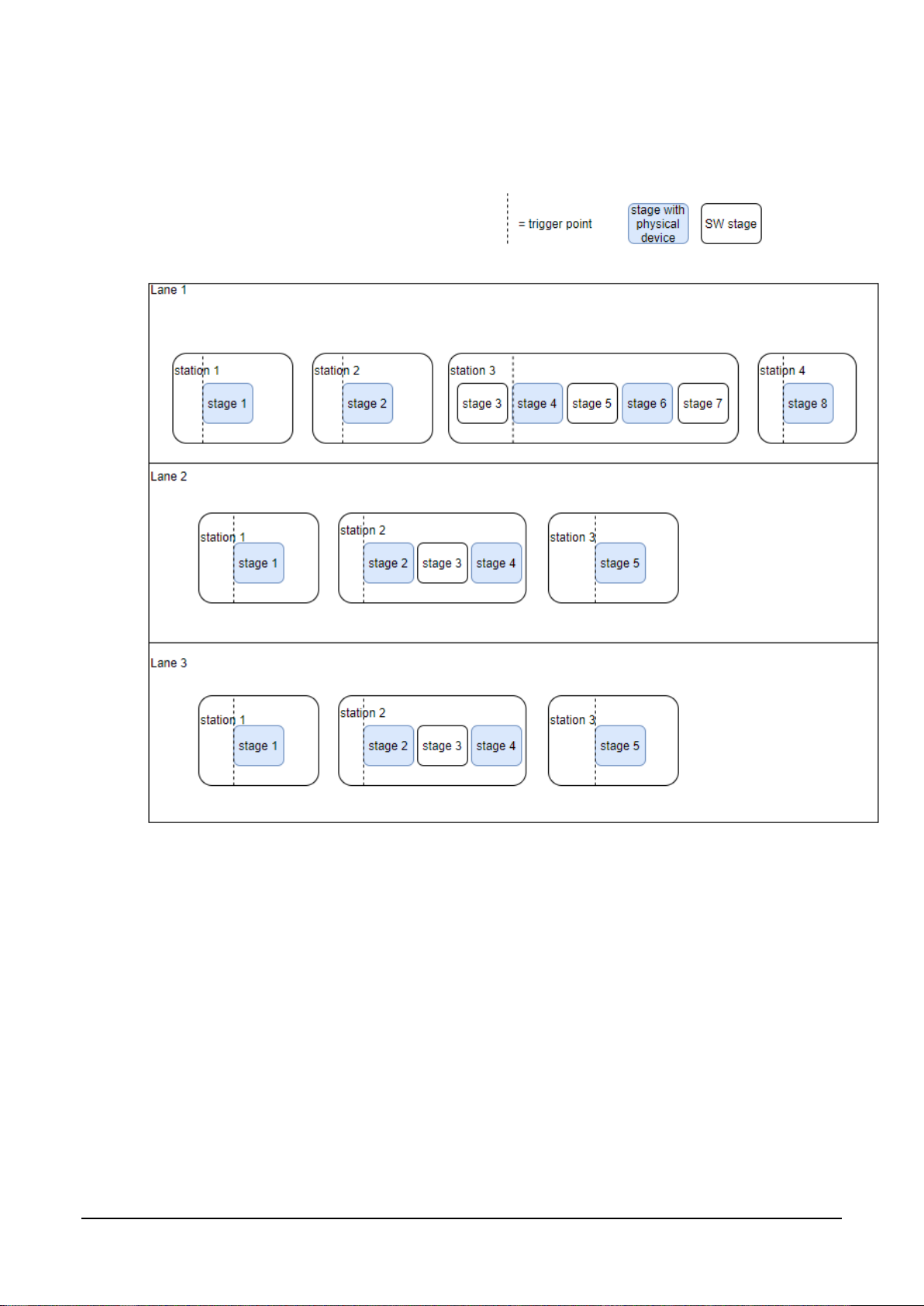
2.1 Visualization of the lanes, stations, and stages................................................................................. 10
3System components................................................................................................................................11
3.1 Tagsurance controller........................................................................................................................ 11
3.1.1 Server ........................................................................................................................................ 12
3.1.2 Router........................................................................................................................................ 13
3.1.3 PoE switch................................................................................................................................. 14
3.1.4 USB hub..................................................................................................................................... 14
3.1.5 USB-to-serial adapter ................................................................................................................ 14
3.1.6 Lane controller........................................................................................................................... 15
3.2 Trigger sensor.................................................................................................................................... 16
3.3 Rotary encoder .................................................................................................................................. 16
3.4 Station devices .................................................................................................................................. 17
3.4.1 Tagsurance UHF ....................................................................................................................... 17
3.4.2 Tagsurance SL UHF.................................................................................................................. 17
3.4.3 Tagsurance HF.......................................................................................................................... 18
3.4.4 Marker........................................................................................................................................ 18
3.4.5 Puncher...................................................................................................................................... 19
3.4.6 IO-only device............................................................................................................................ 19
3.5 IO Breakout........................................................................................................................................ 19
3.6 Strobe Light ....................................................................................................................................... 20
4Installation................................................................................................................................................21
4.1 Installing Snoop Pro coupling elements ............................................................................................ 22
4.1.1 Verifying Snoop Pro installation (verifying RF connections)...................................................... 22
4.2 Installing the rotary encoder .............................................................................................................. 24
4.3 Installing the trigger sensor ............................................................................................................... 25
4.3.1 Installing and training SICK contrast sensor.............................................................................. 25
4.3.2 Installing and training SICK color contrast sensor..................................................................... 27
4.4 Installing stations ............................................................................................................................... 29
4.4.1 Tagsurance SL UHF.................................................................................................................. 29
4.4.2 Tagsurance UHF ....................................................................................................................... 30
4.4.3 Tagsurance HF.......................................................................................................................... 30
4.4.4 Marker........................................................................................................................................ 31
4.4.5 Puncher...................................................................................................................................... 31
4.4.6 IO-only device............................................................................................................................ 32
4.4.7 IO cable for Voyantic devices.................................................................................................... 33
4.5 Connecting cables ............................................................................................................................. 34

Tagsurance 3 Manual
Copyright © 2023 Voyantic Ltd. All rights reserved. 3
4.5.1 Rotary encoder and trigger sensor............................................................................................ 34
4.5.2 Stations...................................................................................................................................... 34
4.5.3 IO Breakout................................................................................................................................ 34
4.5.4 Strobe Light................................................................................................................................ 35
4.5.5 Machine IO................................................................................................................................. 36
4.5.6 Lane controllers ......................................................................................................................... 36
4.5.7 Tagsurance network .................................................................................................................. 36
4.6 Connecting to the Tagsurance system.............................................................................................. 37
4.6.1 Direct connection....................................................................................................................... 37
4.6.2 Network connection ................................................................................................................... 37
4.6.3 APIs ........................................................................................................................................... 39
5Building lane configuration ....................................................................................................................40
5.1 Lane controller................................................................................................................................... 41
5.1.1 Machine IO................................................................................................................................. 42
5.2 Stations.............................................................................................................................................. 43
5.2.1 Tagsurance UHF 1.x.................................................................................................................. 43
5.2.2 Tagsurance HF.......................................................................................................................... 44
5.2.3 Tagsurance SL UHF.................................................................................................................. 44
5.2.4 Marker........................................................................................................................................ 44
5.2.5 Puncher...................................................................................................................................... 44
5.2.6 IO-only device............................................................................................................................ 44
6Building a recipe......................................................................................................................................45
6.1 Recipe Builder overview.................................................................................................................... 45
6.1.1 Recipe Builder installation ......................................................................................................... 46
6.2 Add stations....................................................................................................................................... 46
6.3 Define task lists for stations............................................................................................................... 47
6.3.1 Task list for Tagsurance UHF & Tagsurance SL UHF .............................................................. 47
6.3.2 Task list for Tagsurance HF....................................................................................................... 51
6.4 Variables and mapping definitions..................................................................................................... 53
6.5 Example case of recipe building........................................................................................................ 53
7Running a job...........................................................................................................................................55
7.1 Updating a lane configuration............................................................................................................ 55
7.2 Selecting a recipe.............................................................................................................................. 56
7.3 Job configuration ............................................................................................................................... 56
7.3.1 Job type selection...................................................................................................................... 56
7.3.2 Trigger settings.......................................................................................................................... 60
7.3.3 Lot settings................................................................................................................................. 62
7.3.4 Cut mark .................................................................................................................................... 63

Tagsurance 3 Manual
Copyright © 2023 Voyantic Ltd. All rights reserved. 4
7.3.5 Action trigger.............................................................................................................................. 65
7.4 Results............................................................................................................................................... 66
7.4.1 Results in operator UI................................................................................................................ 66
7.4.2 Result saving ............................................................................................................................. 68
7.4.3 Error codes ................................................................................................................................ 69
7.5 Metrics in operator UI ........................................................................................................................ 71
8Hardware maintenance............................................................................................................................72
9Updating the software .............................................................................................................................73
9.1 Tagsurance controller........................................................................................................................ 73
9.2 Lane controller firmware.................................................................................................................... 73
9.3 Updating Voyantic stations................................................................................................................ 73
9.3.1 Tagsurance UHF ....................................................................................................................... 73
9.3.2 Tagsurance HF.......................................................................................................................... 74
9.3.3 Tagsurance SL UHF.................................................................................................................. 74
10 Technical specifications .........................................................................................................................75
10.1 RF performance................................................................................................................................. 75
10.2 Digital IO of lane controller ................................................................................................................ 75
10.2.1 IO cables.................................................................................................................................... 75
10.2.2 Trigger connector....................................................................................................................... 75
10.2.3 Rotary encoder connector ......................................................................................................... 76
10.2.4 Station connector....................................................................................................................... 76
10.2.5 Machine IO connector................................................................................................................ 79
10.2.6 Output signal current limits........................................................................................................ 80
10.3 Standard Tagsurance 3 device IO port.............................................................................................. 81
10.4 Digital signals of IO Breakout ............................................................................................................ 82
10.5 APIs ................................................................................................................................................... 82
10.5.1 REST API................................................................................................................................... 82
10.5.2 AsyncAPI ................................................................................................................................... 82
11 Appendix: How to Configure the Pattern Trigger.................................................................................83
11.1 What is the Pattern Trigger................................................................................................................ 83
11.2 How Pattern Trigger Works ............................................................................................................... 84
11.3 Pattern Trigger Configuration ............................................................................................................ 85
11.3.1 Active and Passive Sections...................................................................................................... 85
11.3.2 Trigger Location Offset.............................................................................................................. 86
11.4 Simulated Triggers............................................................................................................................. 86
11.4.1 Simulated Trigger with Pattern Trigger...................................................................................... 86
11.5 Hold Off Distance............................................................................................................................... 88

Tagsurance 3 Manual
Copyright © 2023 Voyantic Ltd. All rights reserved. 6
1 Overview
The Tagsurance 3 system is a turnkey solution for testing UHF and HF RFID tags in tag
production machines. It is optimal but not limited to be used in chip attachment, label converting,
and final personalization stages.
Voyantic delivers the Tagsurance 3 system complete with stations that conduct the tag testing
and encoding. The trigger signal to the system can come either from the machine or from a
trigger sensor delivered by Voyantic. Depending on the use case, we strongly recommend to
connect the trigger sensor to Tagsurance 3, as trigger filtering features, such as pattern filtering,
are then available. Tagsurance 3 comes with its own rotary encoder for location sensing. All IO
signals necessary for operating the system are handled within the system itself and do not need
interfacing with the machine.
Tagsurance 3 uses its own configuration and recipe for a job and then initializes the stations
accordingly so that they know what to do when the lane controller triggers them. The lane
controller handles the triggering of all stations on the lane when tags travel past. Each station
sends its result as data (serial port or Ethernet) to the Tagsurance controller PC and the system
then gathers the job results from this data.
Tagsurance 3 is easy to integrate to a production line or machine, as it can work independently
and does not necessarily need to interface with the machine or logic controlling the production
line.
Tagsurance 3 is simple and quick to configure for the machine. This lane configuration contains
information on where and how trigger sensor, Snoop Pro coupling elements, marker and other
such stations are installed.
Tagsurance 3 is easy to operate with a browser-based operator UI that acts as a server in your
computer connected to Tagsurance 3 and browser pointed to Tagsurance 3’s IP address:
•Either via connecting Tagsurance 3 to your internal network from which it receives its IP
address via DHCP
•Or as a point-to point connection to a fixed IP in the system.
As your computer will receive an IP address in the same range via DHCP, in most cases there is
no need for changing the settings on it.
Tagsurance 3 also allows machine manufacturers or end users to build their own operator user
interface, as the system offers a complete REST API and AsyncAPI which have the same
functionality as is used by Tagsurance 3’s own operator UI. Voyantic reserves the right for some
limitations in special cases.
Tagsurance 3 can interface with the machine via a machine IO that can offer, for example, start
and stop signals to the machine that can be connected when you want to control such operations
by the Tagsurance 3 system.

Tagsurance 3 Manual
Copyright © 2023 Voyantic Ltd. All rights reserved. 7

Tagsurance 3 Manual
Copyright © 2023 Voyantic Ltd. All rights reserved. 8
2 Terminology
Term
Meaning
Tagsurance 3
The whole system is called Tagsurance 3
Operator
Person that runs the machine in production.
Does not necessarily need to know anything about the recipe, except for
loading the correct one.
Does not need to know anything about machine configuration, but rather
needs to switch shielding plates and snoops according to the recipe in
use.
Production engineer
Plans the recipes needed for production.
Distributes recipes to operators.
Job
Contains the recipe and optional information about the job, such as job
label and lot size.
Recipe
Instructions for the system of what is to be done to each tag, e.g., “2 point
tests and TID read” and “mark failed tags”.
The recipe needed for a machine anywhere in the world to test and/or
encode labels in a certain job by an operator as required by a production
engineer.
Lot
The subset of a job. The lot number is automatically incremented after
predefined number of tags are processed. Lot number is included into the
tag result.
Lane
In the material under process: one lane of tags going through the process
one by one.
In the machine: stations that process the lane of tags going through the
machine.
Can be the only lane in a single-lane or one of the lanes in a multilane
setup.
Lane configuration
Defines which devices are on a given lane and in which order.
Contains the device configuration.
Device configuration
Each device has its device specific settings configured here. The idea is to
set it once for each device and these configurations are then just used as
building blocks for lane configurations.
Lane controller
Device for controlling stations on a single lane, either the only lane in a
single-lane setup or one of the lanes in a multilane setup.

Tagsurance 3 Manual
Copyright © 2023 Voyantic Ltd. All rights reserved. 9
Station
Defines a physical device on the lane.
Includes 1-N stages one of which must be a physical device.
Any stage in a station before the first physical device stage is executed as
soon as possible and all stages after the first physical device stage are
executed as soon as possible after the triggered stage is executed.
There are two types of stations:
•Feedback stations such as Tagsurance UHF, that affect the tags’
pass/fail result
•Silent stations such as marker and puncher, that do not affect the
tags’ pass/fail result, yet may affect the tag itself
Stage
Defines any operation (related to HW device or SW process) that:
•takes in a tag data object
•modifies it
•outputs a tag data object
Is always included in a station.
When a stage is the first physical device within a station, it is the trigger
point within a station. The stages are always executed in the order they
are defined within a station, and the execution stops at each first physical
device within a station until that station is triggered.
Task list
Instructions for each stage.
Tagsurance controller
The whole rack with everything that is inside.
PoE
Power over Ethernet. This is how Lane controller and Tagsurance SL UHF
are powered to reduce number of cables and power bricks needed.
Trigger
Sensor that is used by Lane controller to sense when tags enter the
process.
Rotary encoder
Sensor that is used by Lane controller to sense accurately how material is
moving.

Tagsurance 3 Manual
Copyright © 2023 Voyantic Ltd. All rights reserved. 10
2.1 Visualization of the lanes, stations, and stages

Tagsurance 3 Manual
Copyright © 2023 Voyantic Ltd. All rights reserved. 11
3 System components
3.1 Tagsurance controller
Tagsurance controller is the main unit of the Tagsurance 3 system. The Tagsurance controller:
•follows the flow of tags in the process;
•triggers the testing and encoding stations when the tags are on the coupling elements;
•collects the results;
•provides interfaces to the operator and a client system to take advantage of all the data.
The Tagsurance controller consists of a few components listed below. The number and
configuration of components may vary according to customer requirements.
Different variants of Tagsurance 3 Controller racks:
1 lane
1–6 lanes
1–12 lanes
Rack type
19”
19”
19”
Rack capacity
4U
8U
12U
Dimensions
See the Product catalogue.

Tagsurance 3 Manual
Copyright © 2023 Voyantic Ltd. All rights reserved. 12
Tagsurace 3 controllers which can handle up to 4 and up to 12 lanes
3.1.1 Server
Located on the rack unit, the server is installed highest on the rack.
As the specifications for racks of different sizes may differ, the server can comply with higher
system throughput with a higher number of lanes.
Note: The server is not to be connected to Internet until Voyantic updates the system from
Windows-based to Linux-based. This upgrade will be required in order to update the system also
after it has become available. The possibility to upgrade the system will be announced when
available. The upgrade will not be mandatory, but it is highly recommended. Costs may be
involved depending on the system configuration and the time of the original purchase.
3.1.1.1 Updating the software (patching and feature updates)
Updates to the software are currently handled manually following the instructions provided by
Voyantic. As Voyantic adheres to semver.org in versioning, do NOT expect a major version (e.g.
1.2.3 → 2.0.0) to be backward compatible. See the API specification for detailed information on
backward compatibility and API version life cycle.
3.1.1.2 Security
As there is no automated or monitored patching by Voyantic for the operating system (Windows
10 Pro) or software installed by Voyantic, the Tagsurance 3 system is not to be connected to the
Internet, but rather only a local *Ethernet connection should be used.
3.1.1.3 Updates and security
An update will be available for all customers from Windows-based systems to Linux , also
allowing one-click updates including the possibility for immediate one-click rollback in case
something is not working or is not satisfactory in the new version.

Tagsurance 3 Manual
Copyright © 2023 Voyantic Ltd. All rights reserved. 13
3.1.2 Router
The router is configured to organize the Tagsurance controller network.
Port number
Name
Description
1 (Internet)
WAN port
Port for connecting to the customer network, with or
without Internet connectivity. The network must provide IP
via DHCP.
2
Direct connection
Direct connection with DHCP server with network
segment 10.10.10.0/24. Meant for customers for directly
connecting the computer/server that obtains the IP from
the Tagsurance router and can connect to the API server
through this socket.
3
Tagsurance network
Tagsurance internal network with a DHCP server. It is
connected to any port in the switch and is the network
where all Tagsurance devices (Tagsurance SL UHF,
Tagsurance HF, etc.) will be connected to. The network is
firewalled without any access outside, except to selected
services on the Tagsurance server.
4
Not in use
Not in use
5
Management network
Router management

Tagsurance 3 Manual
Copyright © 2023 Voyantic Ltd. All rights reserved. 14
3.1.3 PoE switch
The Power over Ethernet (PoE) switch is a connection point for all Ethernet devices in the
Tagsurance 3 system. The PoE switch can also be utilized as a power supply for certain devices
like lane controllers. The model and power supply capacity of the PoE switch varies between
Tagsurance 3 controller variants.
3.1.4 USB hub
The USB hub provides enough data connection points for USB devices. All lane controllers are
connected to the USB hub.
3.1.5 USB-to-serial adapter
Systems with Tagsurance UHF testers are equipped with a USB-to-serial adapter because of the
required RS-232 data connection. Depending on the system variant, the adapter has one or eight
serial ports. The systems are preconfigured so that port 1 is COM1, port 2 is COM2, and so on.
The configuration will change if the adapter is replaced after delivery.

Tagsurance 3 Manual
Copyright © 2023 Voyantic Ltd. All rights reserved. 15
3.1.6 Lane controller
Lane controller is a device for controlling the stations on a single lane. The number of lane
controllers in the system defines the maximum number of lanes the Tagsurance 3 system can
manage. Based on the lane configuration, trigger and rotary encoder signals, the lane controller
observes the web movement and triggers the stations via IO connections when a tag is on top of
the coupling elements.
On the front panel, the lane controller has DE-15 connectors for each station on the lane, M12
connectors for the trigger sensor and a rotary encoder, and DB-25 or DE-9 machine IO connector
(version related).
There are two versions of lane controller delivered: The version 0.3.0 has five DE-15 station
connectors and a DE-9 as a machine IO connector. The lane controller version 1.1.0 has eight
station connectors and a DB-25 as a machine IO connector. Regardless the version numbers,
both versions are in production, but Tagsurance 3 Systems are primarily equipped with lane
controllers of version 0.3.0. The version 1.1.0 is currently delivered only in special cases.
Lane controller 0.3.0
Lane controller 1.1.0
See the connectors’ pinout in section 10.2 Digital IO of lane controller.

Tagsurance 3 Manual
Copyright © 2023 Voyantic Ltd. All rights reserved. 16
3.2 Trigger sensor
The trigger sensor is used to detect the individual labels/inlays passing through the system. The
trigger signal introduces a new label to the lane controller which starts the label tracking and
triggers the stations at the right time.
There are two types of trigger sensors available:
•SICK KTM-WP11172P, contrast sensor (standard delivery)
•SICK KTS-WB9114115AZZZZ, color contrast sensor
3.3 Rotary encoder
The rotary encoder is a sensor measuring the liner movement. The lane controller uses the
movement information in label tracking during the process.
If the material is moved backward (reversed), Tagsurance 3 will notice it, if a job is running. The
processing of tags will only start after the liner has moved forward to the position from which the
reversing started.
There is one type of rotary encoder available:
•SICK DBV50E-22APA2000

Tagsurance 3 Manual
Copyright © 2023 Voyantic Ltd. All rights reserved. 17
3.4 Station devices
3.4.1 Tagsurance UHF
Tagsurance UHF is a device for testing the performance of UHF RFID tags. The most common
protocols are supported, and the tests are deterministic. See detailed technical specifications in
the Product catalogue.
3.4.2 Tagsurance SL UHF
Tagsurance SL UHF is a new generation of UHF RFID testers Voyantic is providing. This device
does performance testing like its predecessor and soon also the encoding which enables tag
personalization. See detailed technical specifications in the Product catalogue.

Tagsurance 3 Manual
Copyright © 2023 Voyantic Ltd. All rights reserved. 18
3.4.3 Tagsurance HF
Tagsurance HF is a device for testing the performance of HF RFID tags, such as NFC labels.
The most common protocols are supported, and the tests are deterministic. See detailed
technical specifications in the Product catalogue.
3.4.4 Marker
HSA Jet Micron MCHP1
The print images can be designed by MicroDraw software.

Tagsurance 3 Manual
Copyright © 2023 Voyantic Ltd. All rights reserved. 19
3.4.5 Puncher
Voyantic does not offer punchers but rather a signal interface to fire a puncher at the correct time
to crunch a chip in a failed tag. For more information on puncher signaling, see section 4.4.5
Puncher under Installation.
3.4.6 IO-only device
It is possible to connect other than devices provided by Voyantic as a station to the Tagsurance 3
system. The devices must implement a specific IO signal interface that the Tagsurance 3
controller uses to trigger the device when it is time to start processing the tag. The device is
expected to report back whether the processing was successful or not.
The pass-fail results of IO-only devices are shown in the Tagsurance 3 operator UI and added to
the logged tag results. The initialization and advanced result handling of the IO-only device must
be done separate from the Tagsurance 3 system, for example, by using the device’s own UI.
For more information on IO-only device signaling, see section 4.4.6 IO-only device under
Installation.
3.5 IO Breakout
The IO breakout is an access point to IO signals between a lane controller and a station. The IO
breakout provides the trigger, busy/ready and pass/fail signals at both types of outputs: NPN and
PNP, and these outputs are isolated from the original signals coming from lane controller and
station.
With the help of IO breakout, for example, the station trigger signal can be safely distributed to
the PLC without the risk of interference with sensitive IO signals.
Note: The IO breakout has only signal outputs. You cannot input the signals to the IO breakout.

Tagsurance 3 Manual
Copyright © 2023 Voyantic Ltd. All rights reserved. 20
3.6 Strobe Light
The strobe light is an accessory to help observing the RFID tag position when the station is
triggered. The strobe light is connected in between the station IO cable and the station. The
duration of the flash is fixed and independent from the trigger signal pulse length.
Table of contents
Popular Industrial Equipment manuals by other brands

Let's Go Aero
Let's Go Aero GearDeck H00604 product manual

Baumer Hübner
Baumer Hübner POG 90 Installation and operating instructions

Cold Jet
Cold Jet PR120H user manual

Harmonic Drive
Harmonic Drive CSD-2A Component Sets engineering data

Oriental motor
Oriental motor alphaSTEP ARL Series Setting manual

woodmizer
woodmizer PD200 Series Safety, Operation, Maintenance & Parts Manual

Flex-A-Seal
Flex-A-Seal 58 Installation, operation, maintenance guide

System air
System air SAVE VTR 700 Installation and service

DryAIR
DryAIR ES200 Fan-Coil Operator's manual

Alfalaval
Alfalaval ALT-SB-15 instruction manual

Haufftechnik
Haufftechnik HRD Series Assembly instruction

Ebmpapst
Ebmpapst W2E200-HK86-01 operating instructions