USER MANUAL VPC USER MANUAL VPC
04/09/21 04/09/21
For more information visit vpc.com For more information visit vpc.com
RETURN TO INDEXRETURN TO INDEX
Slides are used with the 9050 and 9050TR receiver. The receiver
includes a mounting bracket kit and hardware. Choose your slide kit
based on the distance from rail to rail and verify that the slides will
not interfere with the rack enclosure. Each kit will support 180 lbs.
TOOLS REQUIRED
Phillips Head Screwdriver
/32 Allen Wrench
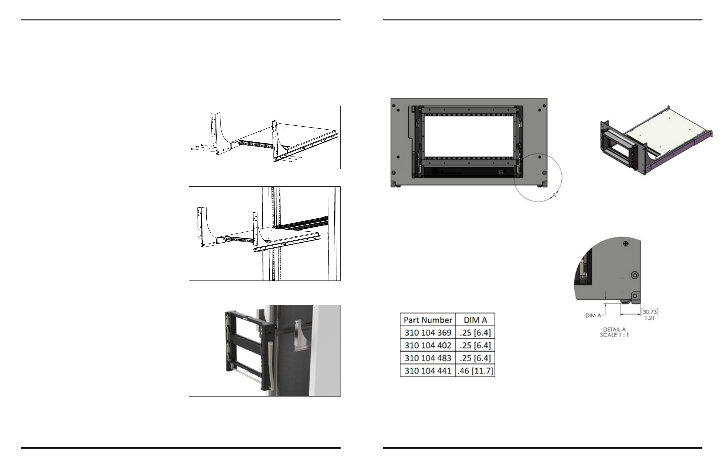
DETERMINE YOUR SLIDE KIT
1. Measure dimension A to determine the proper slide kit, ensuring the slide
length does not exceed dimensions A + B (Figure A).
LOCATE AND MOUNT SLIDES
1. Determine an appropriate location in the rack to mount the slides and
receiver. Keep in mind that the cables connecting to instrumentation not
placed on the instrument bracket will need to be long enough for the slides to
fully extend without putting tension on the cables.
NOTE: The “Cable Management” section of the Master catalog
can be used as a guide.
2. Install slides using manufacturer’s instructions. A hard copy is included with
the shipment (www.accuride.com/Resources/pdf/3507-r4-0309.pdf). Make
sure the same position mounting holes are used for each side of the front and
back brackets. Do not fully tighten down the 4 front and 4 rear mounting
screws at this time (Figure B).
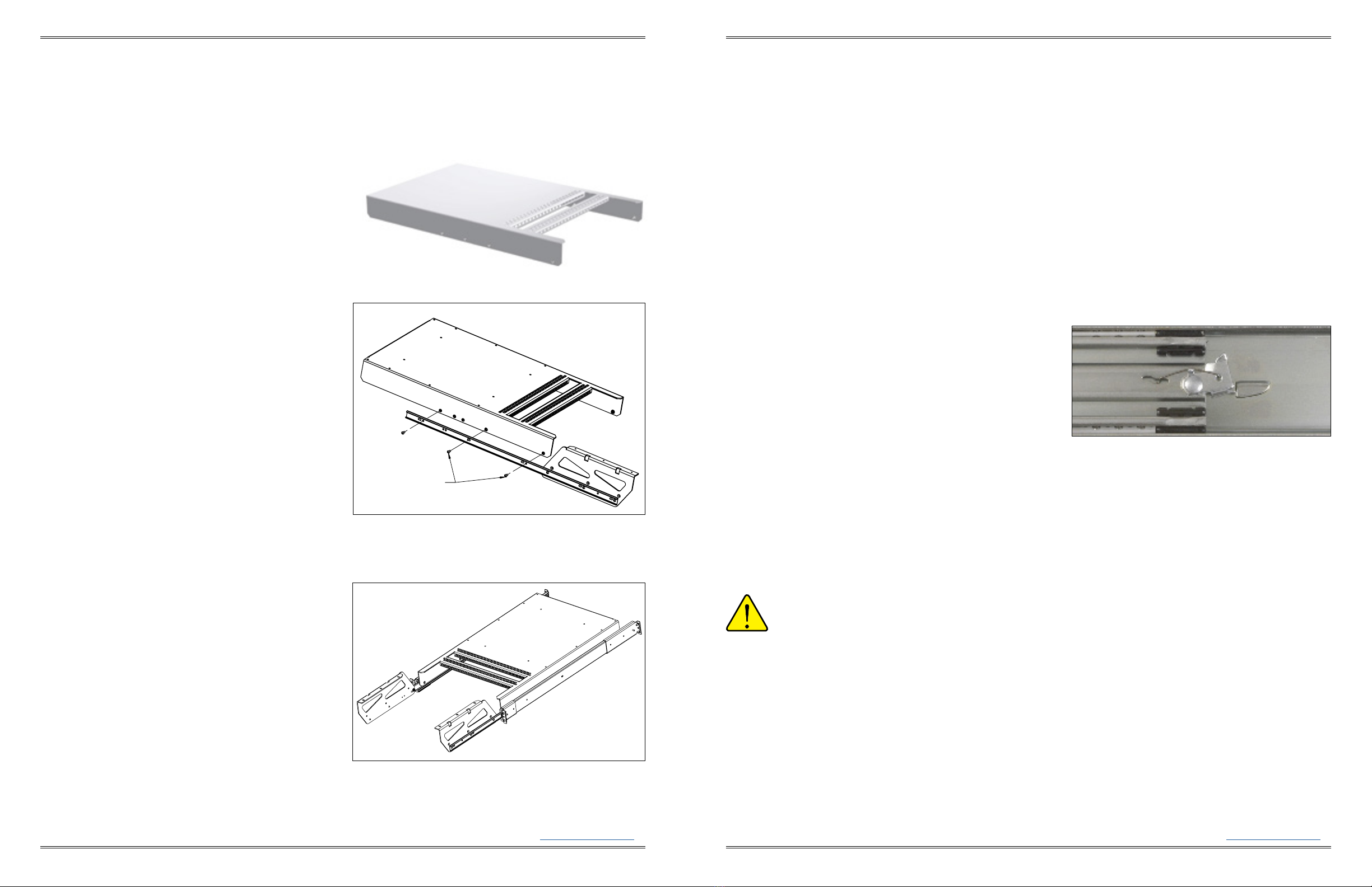
4. Remove the innermost section of each slide by extending the slide fully,
depressing the tab, and continue extending the inner section of the slide until
it is free from the slide assembly (Figure C).
5. Install the instrument bracket and/or cable tray onto the inner sections of
the slide kit following the Instrument Bracket Installation instructions and/or
Cable Tray Installation instructions found in Section 4.
29.50
749.30
TOP VIEW
[50.8]
2.00
DIMENSION B
DIMENSION A
DIMENSION C
[749.3]
29.50
[31.75]
1.25
Figure A. If dimension C exceeds 1" use the Rack Extend-
er Kit, Part # 310 113 406.
SLIDE CONFIGURATION INSTALLATION 9050
RECEIVER, , MODULE, WITH SLIDE MOUNTING • PART #
"SLIDE KIT (FITS "– "DEEP RACKS [. – ]) • PART #
"SLIDE KIT (FITS "– "DEEP RACKS [. – .]) • PART #
"SLIDE KIT (FITS "– "DEEP RACKS [. – .]) • PART #
Dimensions shown: [millimeters]
inches
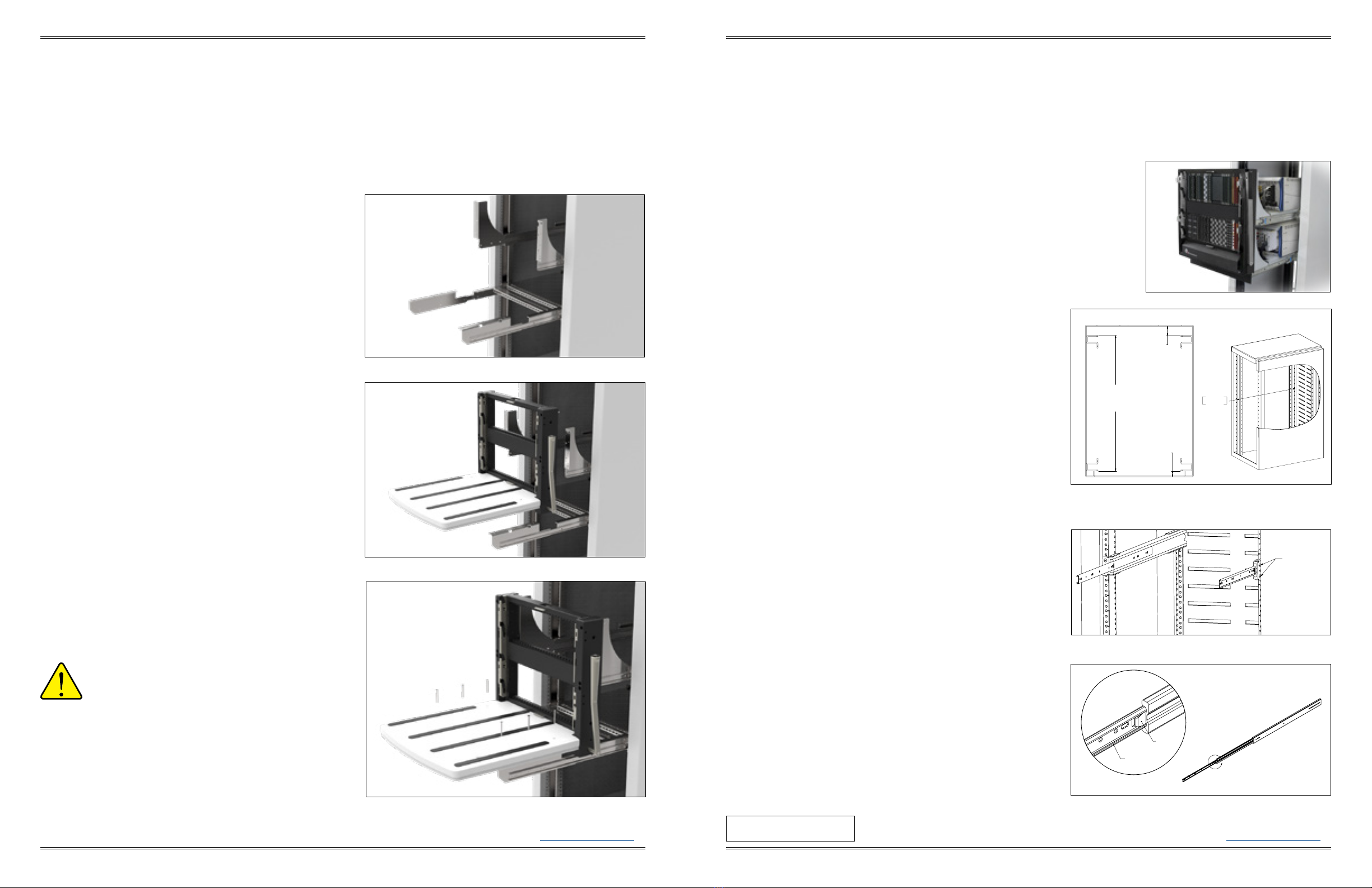
ALWAYS SUPPORT THE RECEIVER AND
PLATFORM WITH THE MOST ROBUST
MIDDLE SECTION OF THE SLIDES.
To ensure proper support when extending the receiver and table away from
the rack, stop the receiver and platform at approximately 6" from the rack.
Reach around to the rear of the receiver to the slides underneath on both
sides. Manually extend the middle section of the slides forward until fully
underneath the platform. The receiver and platform may then be extended
while holding this middle slide in place. If completed properly, the middle
section of the slides will remain underneath the platform and oer the
strongest support.
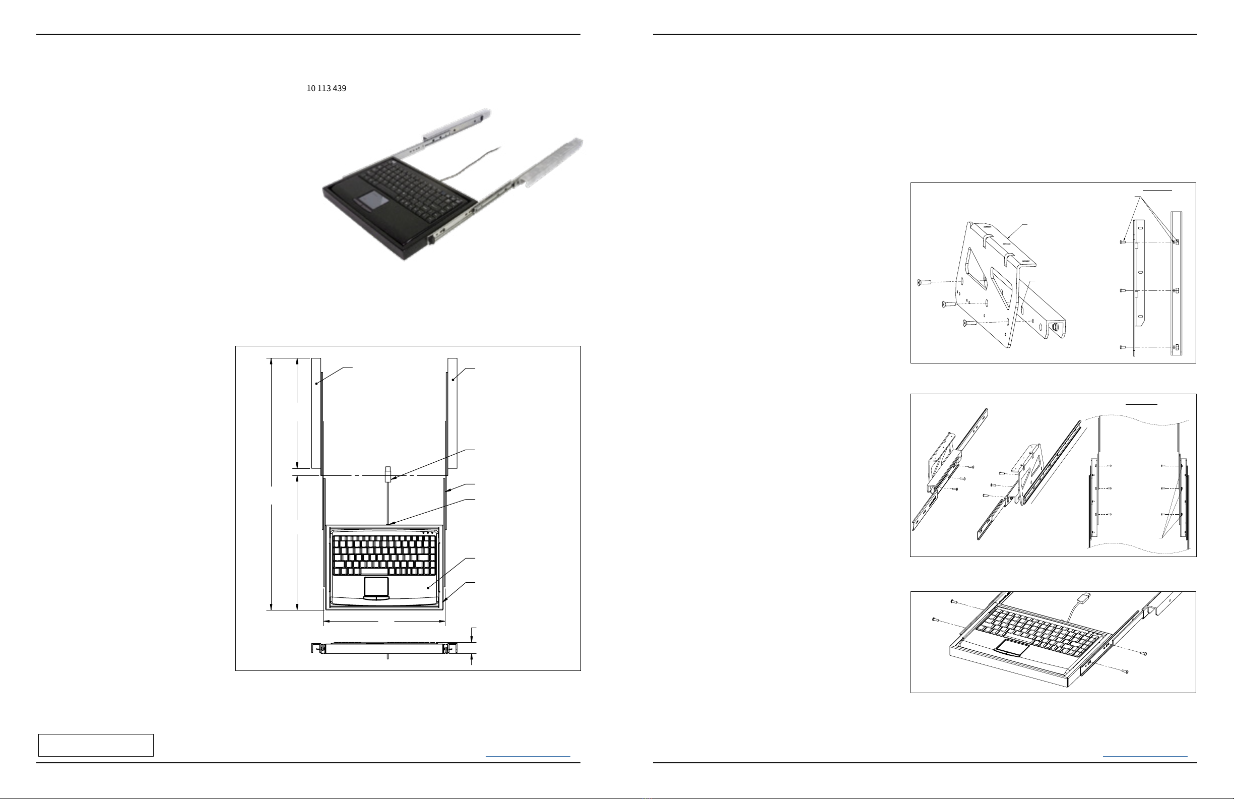
INSTALLATION 9050TR
1. Install inner slides back into slide kit in the rack.
2. Attach the platform mounting flanges to the inner slide rails using the
six 8-32 button head screws provided with the receiver (Figure D).
Do not fully tighten down the screws.
3. Install the 9050TR platform/receiver onto the platform mounting
flanges with the six 8-32 screws (Figure E). Do not fully tighten
down the screws.
4. Pull the receiver out as far as possible. The slides will lock in position.
Push the blue tabs located on the middle section of the slides. Apply
pressure to push the receiver back in toward the rack. The smaller
inner slides move into the middle section, which should not move.
Push receiver until it backs into the rack.
5. Secure the receiver to the rack using the captive 10-32 screws
(Figure F). Be sure to li up on the platform slightly to ensure an
even engagement of the screws.
6. Fully tighten screws in this order:
- 6 8-32 platform mounting screws (as shown in Figure D).
- 6 8-32 button head platform mounting flange screws (as shown in
Figure C).
- 4 front slide mounting screws (Page 2-1, Figure B).
- 4 rear slide mounting screws (Page 2-1, Figure B).
7. Unscrew the 10-32 captive screws and slide the receiver out. Figure E. Install 9050TR into platform mounting flanges.
Figure D. Attach platform mounting flanges to the inner slide
rails.
Figure F. Secure the receiver to the rack with the captive
10-32 screws, taking care to lift up on the platform slightly to
ensure even engagement.
SLIDE CONFIGURATION INSTALLATION 9050TR
RECEIVER, TR, MODULE, WITH "PLATFORM • PART #
"SLIDE KIT (FITS "– "DEEP RACKS [. – ]) • PART #
"SLIDE KIT (FITS "– "DEEP RACKS [. – .]) • PART #
"SLIDE KIT (FITS "– "DEEP RACKS [. – .]) • PART #
A
SLIDE
RELEASE TAB
INNER SLIDE
Figure C. Remove inner section of slide from assembly.
Figure B. Slides installed into rack.
10-32 X 1" MOUNTING
SCREW
2 TYP. EACH SIDE
3 4