VTAC HSD USER MANUAL: SECTION 2 VIRGINIA PANEL CORPORATION
1/9/19
2-2 For the most current information available, visit vpc.com
VTAC HSD INSERT INSTALLATION/REMOVAL INSTRUCTIONS FOR RECEIVER MODULE
PART # 510 170 101
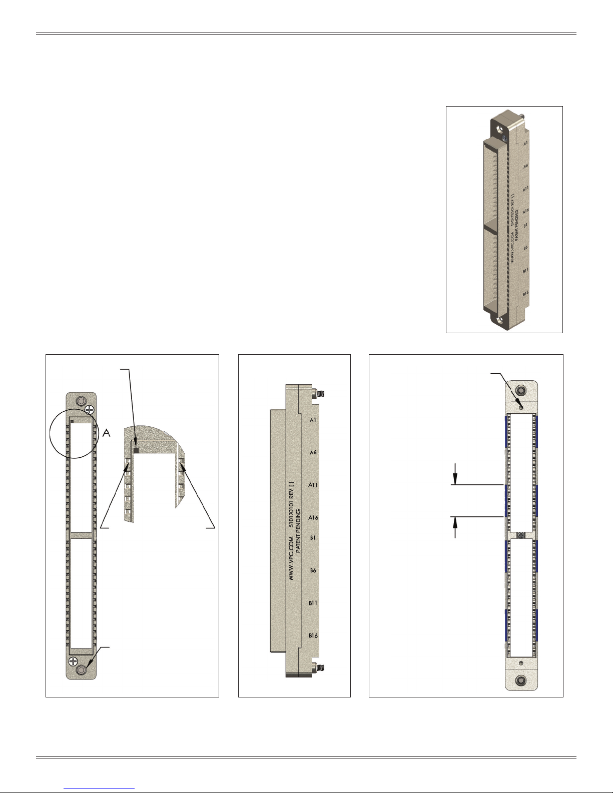
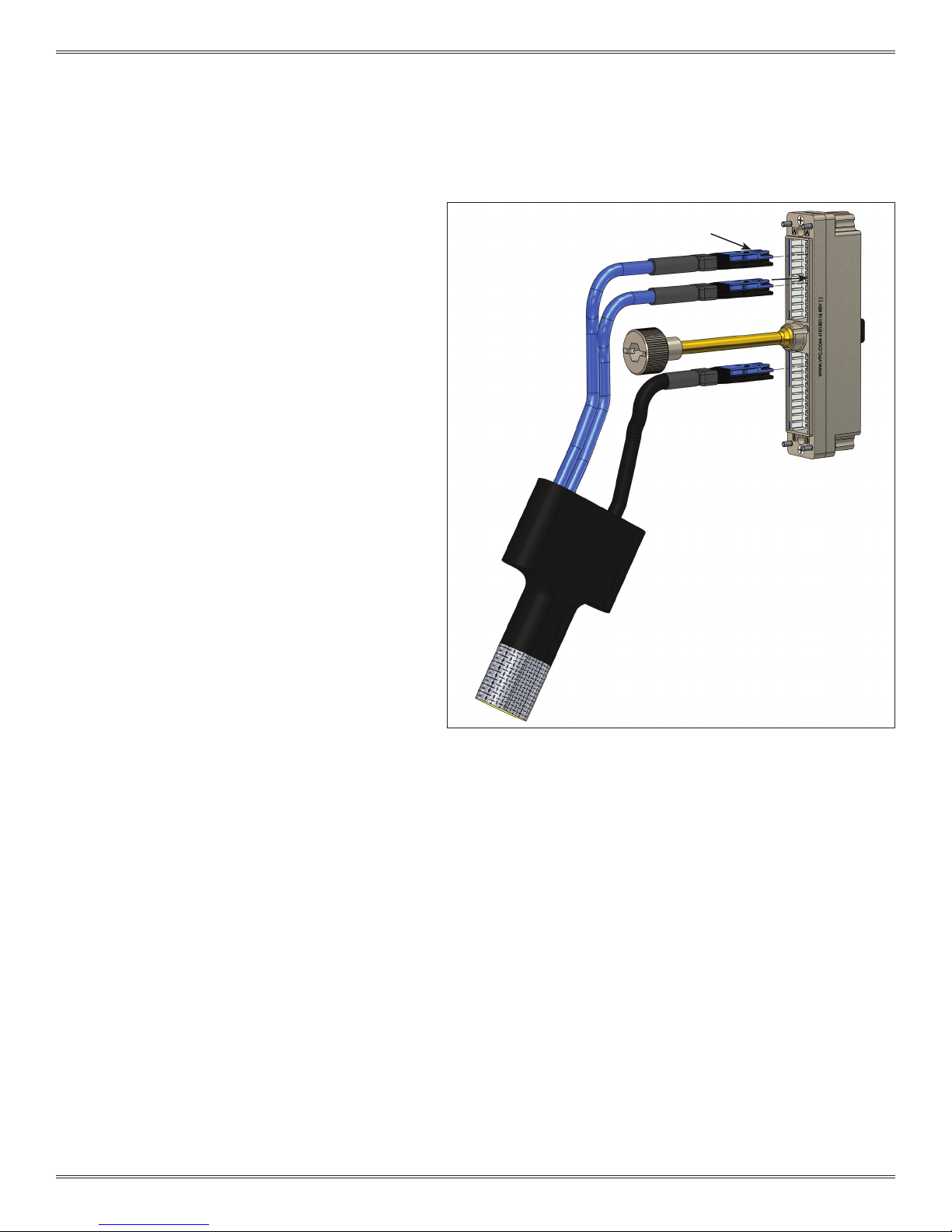
Figure A. VTAC HSD Insert installation.
Figure B. Insert removal tool pins.
TOOLS REQUIRED
VTAC Extraction Tool Kit, Receiver and ITA, Part # 910 112 130
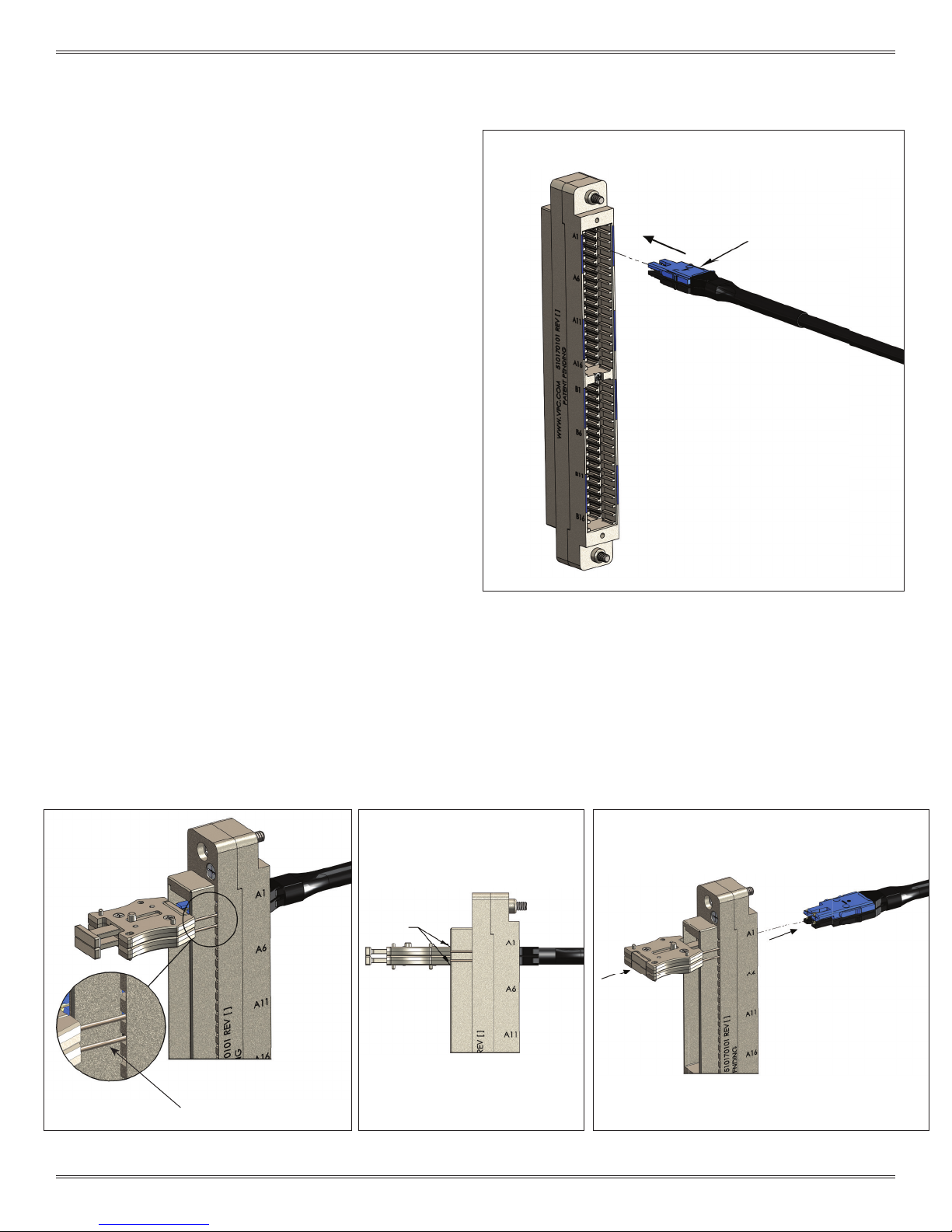
VTAC HSD INSERT INSTALLATION INSTRUCTIONS
1. Ensure that the VTAC HSD Insert(s) is in-line with the
corresponding module location. Apply gentle pressure and
insert the VTAC HSD Insert(s) into the rear (wiring side) of the
module shown in Figure A. The VTAC HSD Insert(s) can only go
into one side. Once in place, gently pull the wire to ensure
the insert(s) is fully seated.
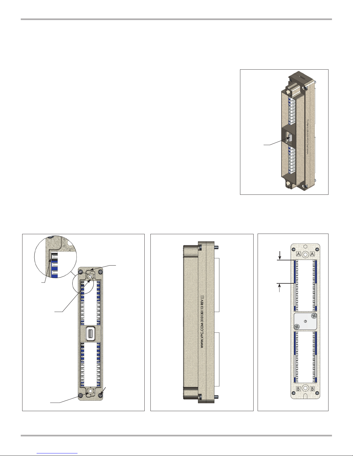
NOTE: To be fully seated, the insert(s) back shoulder should be ush
or below the module rear face as shown in Section 2-1 Figure C.
When plugging a stack of inserts, the blue insert will always be on
top as shown in Section 2-1 Figure A.
VTAC HSD INSERT REMOVAL INSTRUCTIONS
1. Group the required number of extraction tools together for
the given VTAC HSD patchcord shown in Figure B. The tool
pins should be on the mating side of the module.
WARNING: All inserts within each patchcord must be extracted
simultaneously to prevent damage to VTAC HSD Inserts.
NOTE: The extraction tools are magnetic to aid in stacking them
together.
2. While grasping the extraction tool(s) body from the sides
(Figure B),slide tool pins into module’s extraction cavity
square holes until the tool frame is seated against the body
shown in Figure C.
WARNING: The extraction tool(s) need to be seated against
the module front face before the plunger is pushed in. Otherwise
damage to insert(s) may occur.
3. Push plunger of extraction tool(s) in to extract VTAC HSD
Insert(s). The insert(s) will be ejected out the wiring side of the
module shown in Figure D.
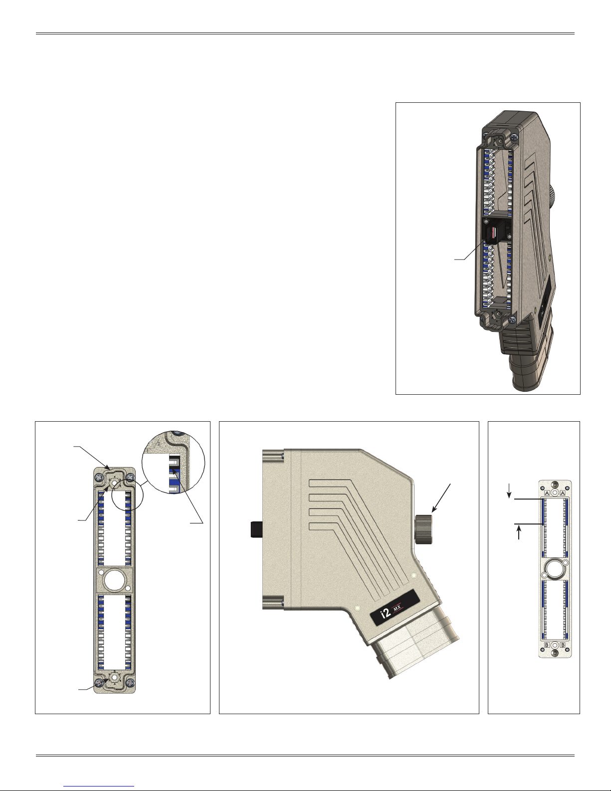
Figure C. Seat removal tool
to module frame.
Figure D. Push removal tool plunger.
GRIP
EXTRACTION TOOL
PINS
DETAIL A
SEAT
PLUNGER
PUSH
PLUNGER
BLUE INSERT