VTAC USER MANUAL VPC
10/10/2022
For more information visit vpc.com
RETURN TO INDEX
8
INSERT INSTALLATION/REMOVAL- SIM MODULE & i2 MX- RECEIVERS
PART # , , ,
INSTALLATION
1. Ensure the VTAC Insert(s) is in line with the corresponding module/ receiver slot(s). Inserts are
installed from the rear side of the receiver/ module. When installing a patchcord containing multiple
VTAC inserts, the blue insert should always be installed on top (Figure A).
2. Load module/receiver beginning at the top and moving downward. Please note, certain patchcords
using thicker wire will require a dierent loading pattern to ensure that patchcords exit the module
with no bend or pressure, resulting in optimal performance. Wire examples include, but are not
limited to RJ45 and Dacar 535. These patchcords should be loaded starting at the top and bottom of
Tier A (Figure A) while making your way toward the center. Recommended loading pattern should
include skipping a slot between a certain number of continuously loaded patchcords. This pattern
will vary based on wire thickness and spacing necessary to maintain wire integrity. (Figure A).
NOTE: Using thicker wire such as RJ45 and Dacar 535 does not allow full population of all available
slot positions. As a result, system design should consider a reduced patchcord capacity per module/
receiver.
3. Apply gentle pressure and the insert(s) should easily snap into place. Force should not be needed
when inserting. If force is required, incorrect orientation is being used for installation. Consult
the VTAC Insert Feature Identification page in this manual for assistance with proper installation
orientation.
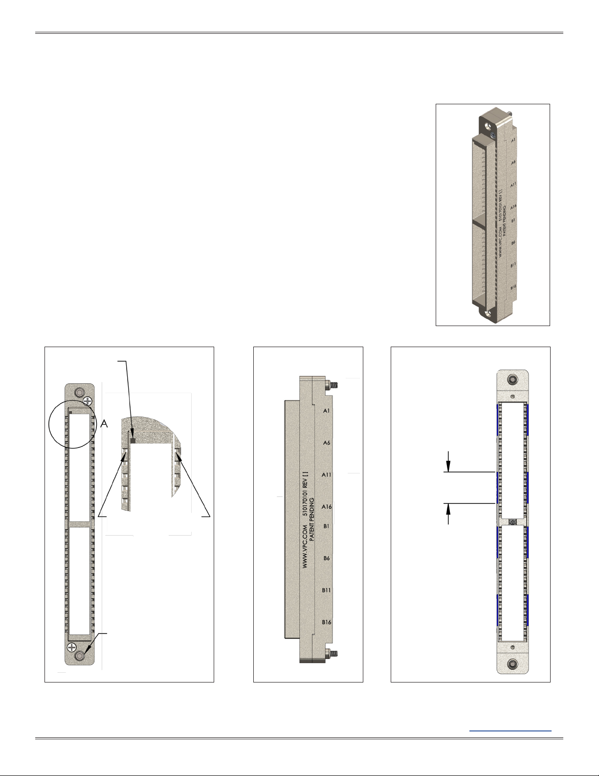
4. The insert(s) is fully seated when the rear of the insert(s) is flush with the rear edge of the module/
receiver frame (Figure B).
REMOVAL
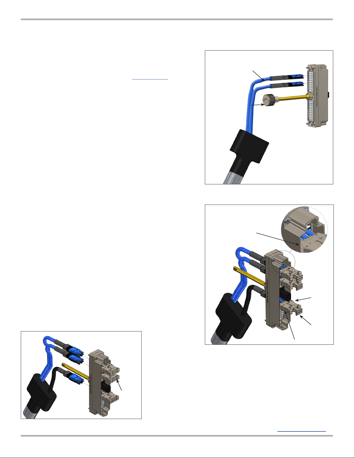
5. All inserts grouped together for a patchcord, must be extracted at the same time.
6. The VTAC Extraction Tools should be grouped together to allow for removal of multiple inserts
simultaneously. Each tool is magnetized and grooved to make grouping easier.
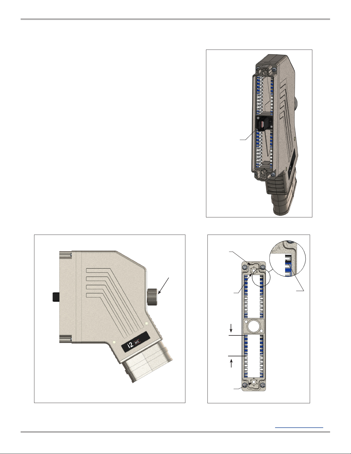
7. The extraction tool is used on the front side of the receiver/ module. Grasp the tool(s) from the
sides and slide the tool pins into the square cavity holes, located externally on the frame of the SIM
Receiver Module (Figure B) and internally on the i2 MX Receiver. The tool frame should be seated
against the frame body, if tool pins are inserted correctly and completely (Figure B).
8. Tool(s) must be seated against the module frame before the plunger is pushed in. Otherwise damage
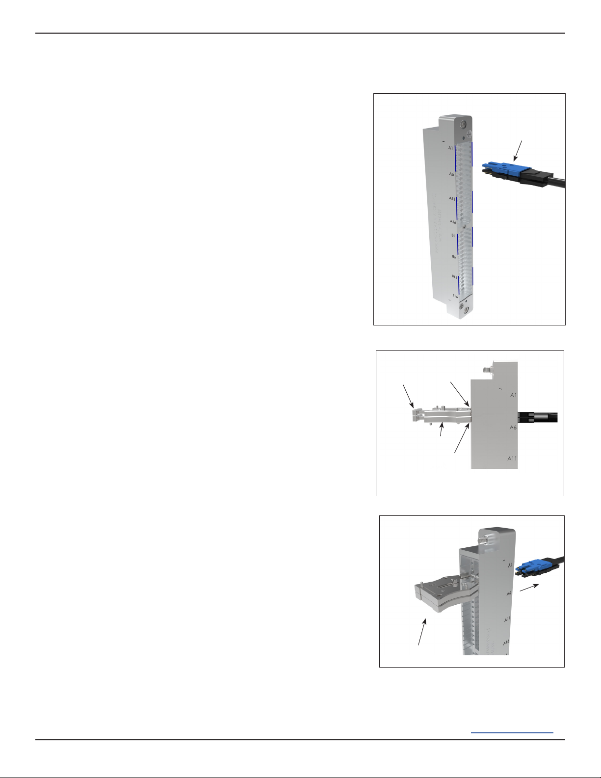
to insert(s) may occur. Push plunger in fully. The insert(s) should be ejected (Figure C).
9. Force should not be needed to extract inserts. If inserts do not extract easily, ensure all pins are fully
seated in the correct location and try again.
Figure C. Extraction
PUSH
PLUNGER
IN
Figure B.
EXTRACTION TOOL
PINS
PLUNGERS
PROPERLY
SEATED
MODULE
FRONT
GRIPS
Figure A.
BLUE INSERT
BLUE INSERT,
RAISED BOSSES
ON TOP
TIER A
TIER B