Operation Manual RTM MP Plus
06.03.2019 4
1.2 List of Safety Instructions
Changes or modifications made to this equipment not expressly approved by
(manufacturer name) may void the FCC authorization to operate this equipment.
This devise complies with Part 15 of the FCC Rules and with Industry Canada licence-
exempt RSS standard(s). Operation is subject to the following two conditions:
(1) this devise may not cause harmful interference, and
(2) this device must accept any interference received, including interference
that may cause undesired operation.
Radiofrequency radiation exposure Information.
This equipment complies with FCC radiation exposure limits set forth for an
uncontrolled environment. This equipment should be installed and operated with
minimum distance of 20 cm between the radiator and your body: This transmitter
must not be co-located or operating in conjunction with any other antenna or
transmitter.
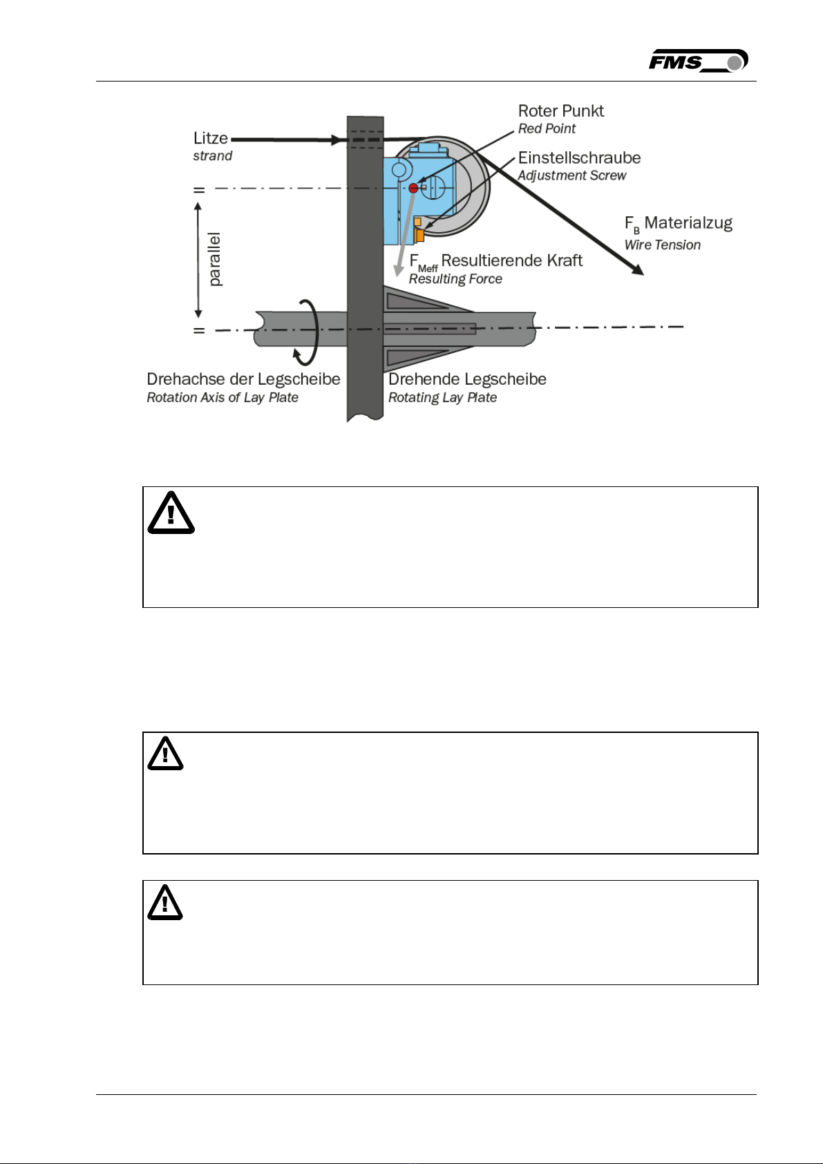
It is of paramount importance to compensate the centrifugal forces caused by the
rotating base plate of the stranding machine. The measuring results will be wrong, if
this rule is broken.
Proper function of the FMS RTM MP System can only be guaranteed with the
recommended application of the components. Other arrangements can cause
malfunctions. Therefore, the installation instructions on the following pages must be
followed.
Local installation regulations are to preserve safety of electric equipment. They are not
taken into consideration by this operating manual. However, they have to be followed
strictly.
The shield should be connected only to the electronic unit. On the force sensor side the
shield should stay open.
Bad earth ground connection may cause electric shock to persons, malfunction of the
total system or damage of the electronic unit! It is vital to ensure that proper earth
connection is done.
The sensor cables must be installed separate from power lines.
2 System Description
2.1 Functional Description RTM MP System
FMS’ RTM MP System has been developed to measure and evaluate all kind of
production relevant parameters in Wire Processing Machinery (especially in Bow Type
Stranding Machines). The System consists of a combined transmitter-decoding unit, a
receiver and further decoding modules in the receiver part. RTM MP uses two force
sensors for the measurement of the wire tension. Encoder signals and wire tension