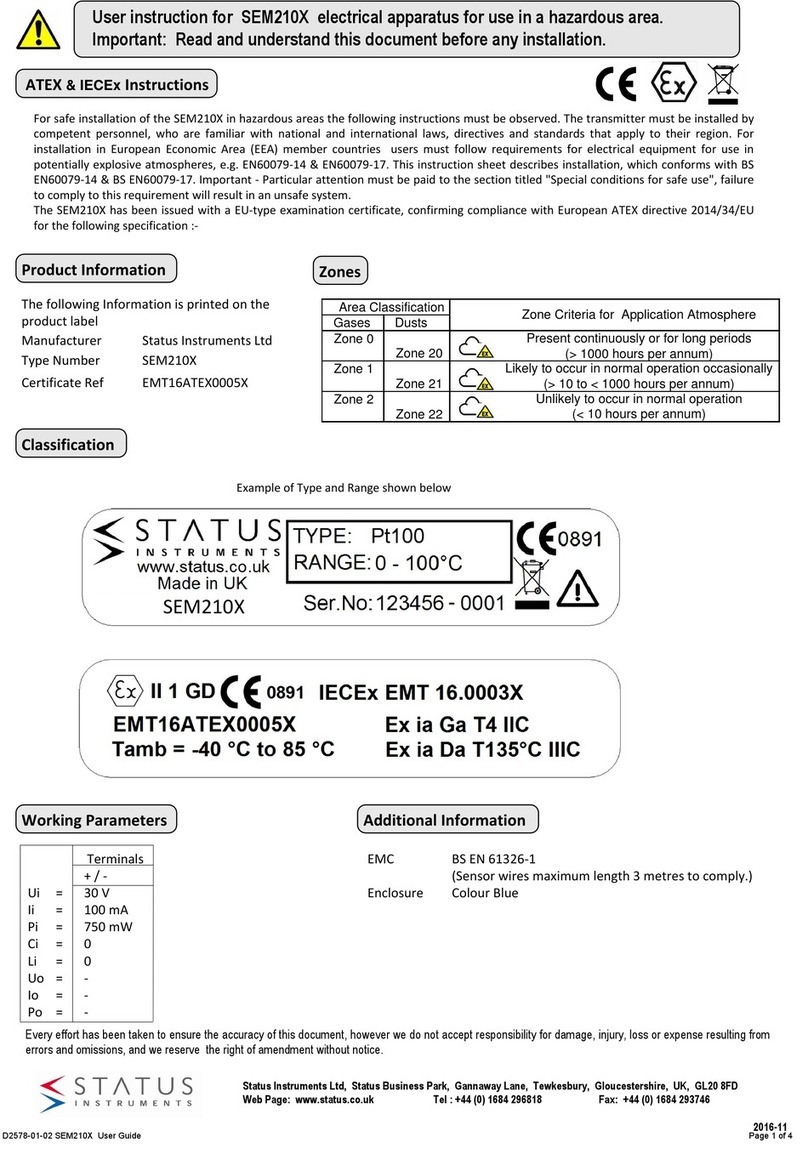
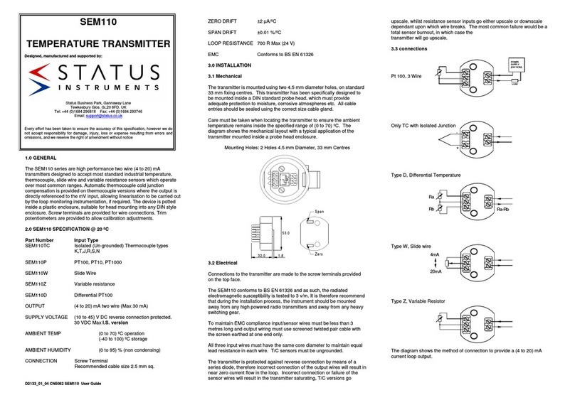
USER DJUST
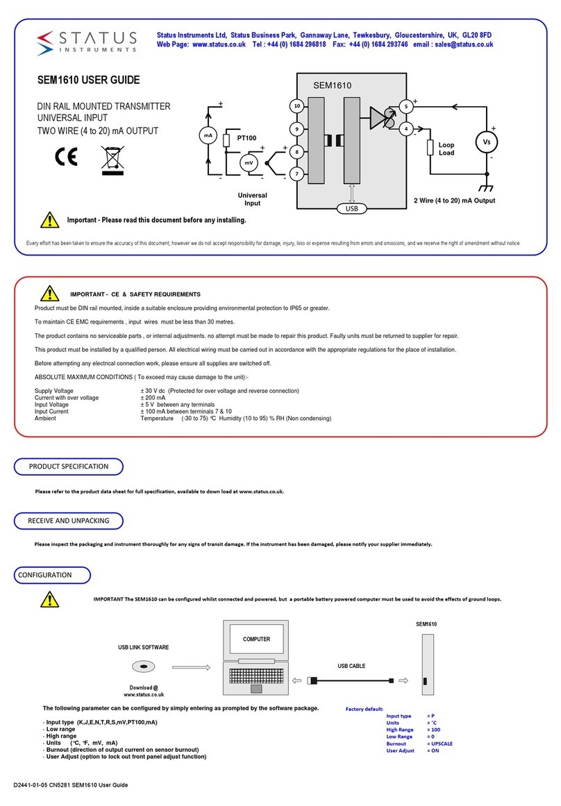
UNIVERSAL INPUT CONNECTION
For cable length < 3 Metres no screen or twist pair required.
Thermocouple inputs must use correct compensation cable.
PT100 inputs all three wire must be equal length (resistance).
Use recommended types for cable length (3 to 30) metres.
m
V
++
-
-
PT10
0
m
A
+
-
Ø 3mm
ELECTRIC L INST LL TION
Screw Driver
Screened Cable Twisted Pair Cable
10
7
7
9
7 7
TC Compensation Cable
Screened
TURN OFF SUPPLY BEFORE WORKING ON NY
ELECTRIC L CONNECTION
Ø 3mm
Screw Driver
20
2020
20.
..
.000
000 000
000
Digital mA meter
Power supply (24V dc)
Input Simulator
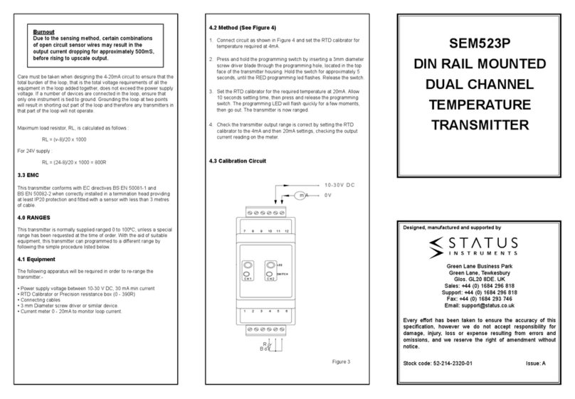
User adjust function allows manual adjustment of the output current,
this is useful for minor calibration adjustment or trimming out any
sensor error, ± 5% of range adjustment is available at both offset and
span. Raise and lower buttons are provided on the front panel, of the
transmitter, accessed using a 3 mm flat blade screw driver. Insert the
screw driver into the appropriate slot to operate the button. The button
has a click action.
METHOD
1.0 Connect transmitter to a suitable input simulator or sensor. Connect
output to a 24V dc supply, connecting a digital m current meter in series
with the output. Turn supply on, set input to either offset or span
calibration point.
+
-
20
2020
20.
..
.000
000 000
000
+
-
SEM1610
or
2.0 Enter adjust menu by pressing "raise" button for > two seconds.
When the adjust menu is open the range LED will flash :-
> 3 s
State LED will indicate djust action
Offset slow toggle
Span fast toggle
Out of trim range
Input out of range
3.0 djust output current by
pressing either the raise or
lower button, single click to
step advance , or press
continuously to auto
advance.
Raise
Lower
4.0 Once adjust is complete
allow 30 seconds with no
button press, the transmitter
will time out and return to
normal operation.
D2441-01-05 CN5281 SEM1610 User Guide
Escape
> 30 s
Enter
The transmitter will
automatically detect the correct
adjust point (offset or span)
based on the output current
drive. Offset will be adjusted
when the current is between
(3.8 to 6) m , span when the
current is between (18 to 22)
m . No trim action occurs at
any other current.
offset
s an
3.8 6 18 22 mA
MECH NIC L INST LL TION
SEM1610 Enclosure
Style DIN 43880 (1 module width)
Material Polyamide 6.6 self extinguishing
Terminals Screw terminal
Cable 2.5 mm Max
Colour Grey
Ø 3 mm
90 mm
MOUNTING
Screw driver
EN50022 DIN RAIL
56.4 mm17.5 mm
1
2
11 1210
987
4 5 6
1 2 3
To fit or release module
Insert screw driver into
slot and lever latch
away from body
1
2
+ 70 °C Max
- 20 °C Min
1
2
T/C
or sensor
Vs
Loop
Load
USB
+
-+
-
10
9
8
7
SEM1610
5
4
OUTPUT
2 Wire (4-20) mA
Max cable length 1000 metres
Use twisted pair cable > 30 metres
SUPPLY (Vs) = (11 to 30) V dc
M X LO D Ohms = (Vs - 11) / 0.021
ADJUST
STATE
ADJUST
STATE
ADJUST
STATE
ADJUST
STATE
ADJUST
STATE
ADJUST
STATE
