manuals.online logo
Brands
  1. Home
  2. •
  3. Brands
  4. •
  5. VSI
  6. •
  7. Paint Sprayer
  8. •
  9. VSI 305 LP User manual

VSI 305 LP User manual

This manual suits for next models

4

Other VSI Paint Sprayer manuals

VSI Legacy Series User manual

VSI

VSI Legacy Series User manual

VSI 110 JAH Service manual

VSI

VSI 110 JAH Service manual

VSI 400 JAH Service manual

VSI

VSI 400 JAH Service manual

Popular Paint Sprayer manuals by other brands

Idex Akron Brass FS100 quick start guide

Idex

Idex Akron Brass FS100 quick start guide

mbp TEL 15BS instructions

mbp

mbp TEL 15BS instructions

Solo 425 Classic Original instructions

Solo

Solo 425 Classic Original instructions

WAGNER AirCoat GM 4100 AC operating manual

WAGNER

WAGNER AirCoat GM 4100 AC operating manual

Graco 1095 HI Operation manual

Graco

Graco 1095 HI Operation manual

Titan MultiFinish 440 owner's manual

Titan

Titan MultiFinish 440 owner's manual

Graco GUSMER D Series instructions

Graco

Graco GUSMER D Series instructions

SNOWJOE Sunjoe 24V-GS-LTW-RM Operator's manual

SNOWJOE

SNOWJOE Sunjoe 24V-GS-LTW-RM Operator's manual

Walther FSP-01 Assembly instructions

Walther

Walther FSP-01 Assembly instructions

Fimco LG-4-3-1 owner's manual

Fimco

Fimco LG-4-3-1 owner's manual

Nordson MicroMax 2 manual

Nordson

Nordson MicroMax 2 manual

Bonide 051 Operation and service instructions

Bonide

Bonide 051 Operation and service instructions

zogics Z-DAS instruction manual

zogics

zogics Z-DAS instruction manual

KISANKRAFT KK-KBS-165 Operation manual

KISANKRAFT

KISANKRAFT KK-KBS-165 Operation manual

Matrix SG 650 Translation of the original instructions

Matrix

Matrix SG 650 Translation of the original instructions

paasche VV Instructions and parts list

paasche

paasche VV Instructions and parts list

Carlisle DeVilbiss JGA-510 Service manual

Carlisle

Carlisle DeVilbiss JGA-510 Service manual

Gardena 11120 Operator's manual

Gardena

Gardena 11120 Operator's manual

manuals.online logo
manuals.online logoBrands
  • About & Mission
  • Contact us
  • Privacy Policy
  • Terms and Conditions

Copyright 2025 Manuals.Online. All Rights Reserved.

De-Icing Applicator Manual
305 LP, 500 ASM, 750 ASM, 1000 ASM, 1600 ASM,
Automated Power Bundle
NOTICE: READING THIS MANUAL IS
MANDATORY BEFORE OPERATING
THIS EQUIPMENT
Warranty Notice:
At VSI, nothing is more important to us than your complete and total satisfaction with our
products and customer service. Proper setup, installation and best maintenance practices are
vital to ensure longevity of your VSI equipment.
Please go through the warranty registration form and procedure for your equipment in order to
register your three year Honda and one year overall product warranty. The warranty form was
sent to the same email address to which you received your invoice. If you cannot find this form,
please contact us at [email protected] . If the warranty is not registered, your warranty
claim may be denied due to improper setup, use or install.
Our equipment is Honda tested and certified so your Honda engine comes with a three year
commercial warranty backed by Honda and any Honda certified repair center.
All other parts* on your equipment are warrantied against defects through VSI for one year from
the date of purchase.
*We do not offer a warranty on pump seals as over 99% of those failures are due to improper
use or running pumps dry.
This warranty is a parts and technical support only warranty, labor is not included.
Corrosion related issues including wire connections are not qualified warranty items.
We are not responsible for loss of product or productivity due to failures of any kind.
Your warranty will be void due to abuse, misuse, neglect, alteration, modification, improper
handling, improper installation, improper maintenance or failure to follow the instruction and
procedures in the VSI manual and warranty registration form.
Warrantied parts must be sent back to VSI within 30 days in order for us to process your
warranty claim. Replacement parts will be invoiced and will not be marked as paid until the
warrantied part items are returned to our manufacturing facility at 150 E Sharon St, Le Center,
MN 56057.
Installing Your Sprayer
Without a wiring harness running from cab to sprayer, installation is a breeze. Simply
set your sprayer on the truck and strap, bolt or chain it down. Yes, it really is that
simple!
There is a digital version of this manual that can be accessed by hitting the “Getting
Started/FAQ” button on the “profile” tab of your VSI Spray Control app. There is also a
“tech support” button that you can hit and it will pre-populate an email with your sprayer
and other info, type your issue above that pre-populated data so our engineer can
review and find a solution and so your salesperson can follow up with you with the right
information.
Before First Use- VERY IMPORTANT
Your spray unit will heavily rely on the onboard deep cell battery. That is why we have
included an onboard charger/battery maintainer. Before first use, plug this in overnight
or until fully charged. The batteries do not come fully charged from the factory. Please
also keep this battery maintained. It is strongly suggested that the sprayer be plugged in
between uses to keep the battery in peak condition. Remember that lead acid batteries
can lose as much as 2% of their charge per day even when sitting idle, this is why we
include the on board battery maintainer and handy built in plug, to keep the batteries
charged and ready for use at all times as pictured below.
After your battery is fully charged, the next most important step is to go to the “profile”
page of the app and connect your sprayer to the nearest WiFi to where it will be
stationed or most often parked. Enter the WiFi name and password into the text fields
and hit the “Save Credentials” button. The WiFi credentials will then be stored on the
sprayer itself and do not need to be saved again. The sprayer is able to remember 10
sets of WiFi credentials and will connect to any available when you push “Connect to
WiFi”. Once you have your WiFi credentials saved the sprayer will try to connect when it
is powered up if any of the networks are in range.
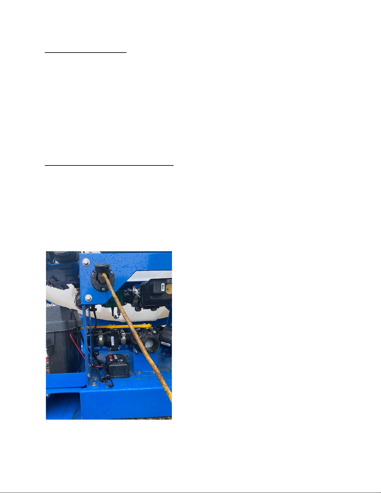
Connecting to Your Sprayer
To begin using your VSI sprayer you must first download the VSI Spray Control App
from either the Google Play store or the Apple App store. Search for “VSI Spray
Control”

and download the app with our logo on it.
Once downloaded, open the app and read the liability prompt. Press OK and go to the
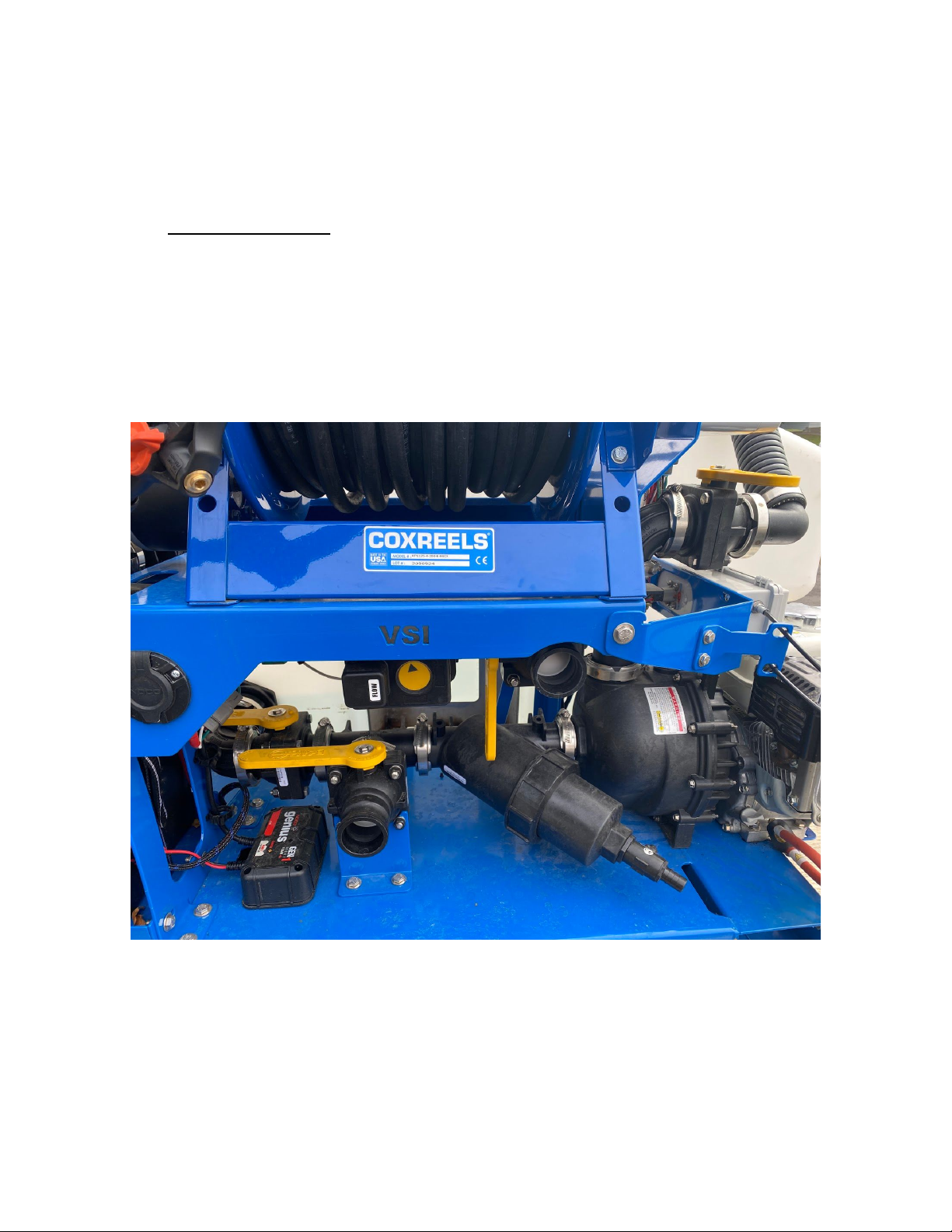
Details tab at the bottom. Make sure your sprayer engine key is in the “on” position.
Your switch can remain in this position all the time without draining the battery.
Now turn on the main switch on the control box and you should see a green light appear
on the switch. You can now press connect on your phone or tablet. You will be shown
all sprayers available within range. Select the sprayer from the list that matches the
serial number of the one you are attempting to connect to. (The serial number can be
found on the side of the control box.) You have now connected to the sprayer and have
control over the unit. No other devices can connect to a unit that is actively paired to a
device. If you want to name it to match the truck it is in or name it for the operator
instead of the serial number you can do so on the details page. VERY IMPORTANT: To
properly save this change and all other data and settings, make sure to press the
“disconnect” button on the details page when you are done with the sprayer. When you
disconnect from the sprayer, the sprayer will save all of the data and settings that have
changed. WAIT 10 SECONDS AFTER DISCONNECTING FROM THE SPRAYER
BEFORE TURNING THE SPRAYER OFF TO ALLOW THE SPRAYER TO SAVE THE
DATA. Simply turning the sprayer off may not save all of your settings or data.
Running Your Sprayer
Once you are connected, you will either have to manually start your engine with the key,
or, if your unit is equipped with our Total Control upgrade, you can go to the
Accessories tab (ACC) and start your engine from that screen.
Once your sprayer is running, your next likely step will be to go to the Details page and
punch into your first job (If you are not tracking the product applied without our app,
continue to the next paragraph.) You can type in which job you are on and then press
Start to begin your job. This will track gallons used, acres covered, gallons sprayed out
of hose reel, and any notes you left for the job. When you are finished spraying for the
day, you press Submit Report and the system will send a CSV file to an email of your
choosing. This file can be integrated into other snow tracking systems if you contact
your provider and ask them to allow the CSV file to sync with their system.
Once you are punched into your job you are ready to go to the Spray tab at the bottom.
Here you have the ability to turn on the lights and strobes on the unit. Next to that is
Operation Mode which lets you toggle between Auto and Manual modes. GPS rate
control is only active on Auto mode, manual mode is a gallons per minute based flow
rate that is not gps/speed dependent.
When in Auto mode, you will be able to change the App Rate, which always defaults to
80 GPA (Gallons Per Acre.) The plus and minus buttons will adjust the GPA by 5 up or
down for each press. When in manual mode, these buttons move the Proportional
Valve, open and close. By holding open or close, you will be allowing more or less
liquid GPM to flow through and be applied out of the selected boom sections.
The three buttons below that are Hose Tracking (with hose reel upgrade,) Ice Buster,
and Boom Lock. Hose Tracking is selected when using the hose reel and will track the
gallons applied through the hose. The Ice Buster button is used when you are spraying
a steady rate but have a section of snowpack, ice or a high priority area that needs a
higher application rate for a short stretch. By pressing this button, your boom sections
will put out a predetermined rate that will be higher than your standard application rates.
This predetermined rate can be changed in the settings menu. The Boom Lock button
will lock out the boom sections so you aren’t able to accidentally turn them on when you
are driving down the road or doing other things on your phone/tablet.
At the bottom of the screen you will find your Boom Section Control buttons. These
control your left, center, and right nozzles. (Only center nozzles if you don’t have the
Three Lane Boom upgrade.)
App Settings
Most of the app settings should be left alone unless you’ve consulted with a VSI
employee first. The tank size is pre-programed to the size of the sprayer, except on
Automated Power Bundles as we do not know which tank size you plan to connect. The
Tank Level will need to be reset every time your sprayer is filled up. Brine blend can be
set to whatever blend the sprayer is running in order to track this information on your job
reports for job costing/margin tracking. The Boom Widths, Minimum Flow, Servo
Speed, and Flowmeter Cal settings should be left alone unless otherwise noted.
This is where you can adjust your Ice Buster setting as previously mentioned. If for
some reason your settings have been changed and you don’t remember what they need
to be at, you can reset them to factory settings at the bottom of the screen.
Make sure that after any settings changes or tank reset you hit the “Save” button at the
bottom right of the screen
Boom Connection Positions
The picture below shows where your hose camlock sections hook up from your spray
boom to your sprayer. The left valve connects to the driver’s side of the three lane
boom. The center valve connects to the middle boom. The right right valve connects to
the passenger side boom. When assembling your hoses, make sure you make it long
enough to reach the furthest of two connection points for each connection on the boom.
A roll of 1” hose and a bag of barbed parts and hose clamps is included with each spray
unit as pictured below.
Valve Functions
Proper valve positioning is vital to your sprayer working correctly for each given task.
Best rule of thumb is that any valves low down on the unit entering the lower part of the
pump housing are suction side valves and any valves high up or connected to the top
side of the pump are pressure side valves.
The images on the following pages indicate proper valve positions for different functions
of the sprayer.
●Application Mode: Your valves are to be in this configuration when you are
applying liquid de-icer. The most common error that is made in application mode
is that the agitation valve (on the upper right of the image) gets left open. This will
rob a majority of the pressure and liquid flow for your system and won’t leave
enough for your sprayer or hose reel to work correctly. The next most common
mistake is that the tank valve (back left of image) gets left closed. With no liquid
getting to the pump, your system won’t work at all and eventually you will burn
out your pump seal.
●Self-Fill Mode: Your hose must be connected to the bottom left camlock and
your valves need to be in the configuration shown when you are using the pump
on your sprayer to self fill from a holding tank. A common mistake made here is
that the tank valve (back left) gets left open, this won’t allow the pump to prime
as it will be sucking air from the tank. The other common mistake when self filling
is that the Agitation valve (top right) gets left closed. The system will still fill this
way as the valve has a hole that allows constant flow through the valve even
when closed (to protect the pump from being deadheaded) but it will take an
exceptionally long amount of time through that bypass. If the tank you are pulling
liquid from is lower than the height of the pump, you may have to prime the pump
by unscrewing the top cap on the pump and allowing the air out of the system. In
some cases you may need to fill the pump housing with liquid to purge the air
fully. Most of the time when filling from a bulk storage tank, this is not an issue,
especially if the fill hose is pre-charged with liquid.
●Pump-Out Mode: Your tank must have liquid in it, your hose must be connected
to the top right camlock and your valves need to be in the configuration shown
when you are using the pump to transfer liquid from the sprayer to another tank
outside of the sprayer. One common mistake here is that the bypass valve (top
right) gets left open, which will still allow the pump-out to work, but it will be
substantially slower than if it is set up properly as shown.
Filter
Each sprayer is equipped with a filter right before where the liquid enters the pump.
Inside is a stainless steel 30 mesh filter that is reusable. If you suspect it is clogged,
close your tank valve and loosen the collar around the filter housing, pull outer housing
off and remove the filter. Rinse clean and place back in the housing.
Spray Boom:
Your spray boom will require bolt together assembly before use. There is a simple
walkthrough video of this process on our youtube channel:
https://www.youtube.com/watch?v=gHtMyaZNyhM
A finished boom can be seen below, and should be set at 20”-28” from bottom of boom
shroud to the ground.
3 Lane Pre Treatment Nozzles
The pre-treatment tips are the bottom ones on each end and the center fan tip, these
are lower flow rate and made for the lower application rates of typical pre-treatment .
These nozzles are to be used when spraying at 20-50 gallons per acre at normal
speeds (2-15 mph). These tips could also be used in applications where you are post
treating in very small lots, on driveways, or other low speed or low volume applications.
3 Lane Post Treatment
The post treatment tips are the top ones on each end and the central boom with a
vertical camlock in the middle that sprays out of the jet nozzle holes in the stainless
pipe. These nozzles are to be used when spraying 70-120+ gallons per acre or when
pre-treating at higher speeds than a typical parking lot such as roadways or large
logistics centers where speeds commonly exceed 12mph.
It is very common for people to want to pre-treat with the jet nozzle holes because they
see local roadway and highway departments leaving “lines” of brine on the road. The
reason they do this is because of the high rate of speed at which they travel on
roadways requiring a heavier jet pattern to not get diluted in the wind, plus they have
very high traffic levels from cars to track the product evenly. Parking lots are different,
lower speeds and less traffic means that a fan tip is preferable, which is why our center
pre-treat nozzle is a fan.
If you run the small outside pre-treat nozzles with the center jets, your application rate