9570-540 – 01/21Page 2
INSTALLATION AND FUNCTION TESTS
1. Initial inspection:
a. Carefully unpack safety breakaway from shipping carton.
b. Inspect safety breakaway for any damage to threads, O-rings,
exterior, etc.
2. Lightly lubricate ALL O-rings on mating connections with
petroleum jelly or other suitable lubricant. DO NOT USE pipe
dope or thread sealant.
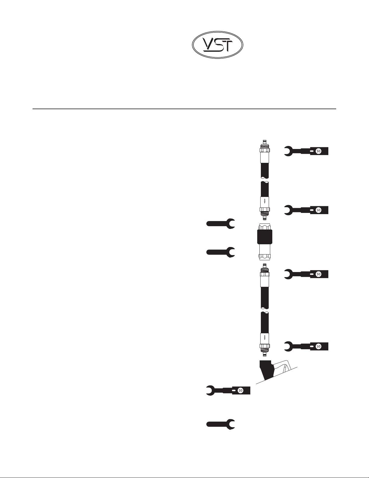
3. Attach breakaway on mating connection and tighten by hand.
NOTE FLOW DIRECTION ARROW (where applicable). Use
the hex on the breakaway body to tighten. DO NOT USE the
breakaway body to tighten the unit.
4. Tighten breakaway connection to 50 ft.-lbs. of torque. DO NOT
OVER TIGHTEN. Use the hex on the breakaway body to tighten.
Use a torque wrench with an open-end attachment to fit the
hose couplings and an open-end wrench to properly tighten
breakaway connections. DO NOT USE channel-locks or pliers
to tighten connections. Proper ft.-lb. torque may not be achieved
with these tools.
5. Purge air from the system by pumping one-tenth (1/10) to two
tenths (2/10) of a gallon of fuel into an approved container.
Inspect each breakaway joint connection for liquid leaks and
meter creep. Make proper adjustments at the breakaway
connection if necessary.
6. Check the nozzle shut-off action by dispensing fuel into an
approved container at least three times to assure proper
automatic operation. To test, operate the nozzle and submerge the
spout tip in fuel until the fuel level covers the vent hole. The main
valve of the nozzle automatically shuts off when liquid covers the
vent hole at the end of the spout. The dispenser should deliver a
minimum of 3 gpm. Hold open latch will disengage automatically
when liquid covers the vent hole in the spout.
7. Measure the resistance between the dispenser outlet casting
and the tip of the nozzle spout. Use an electronic multimeter set
on the high range of the ohmmeter function. Resistance should
not indicate more than 70,000 ohms per foot of hose. Example:
The measured resistance for a 12-foot hose must not exceed
840,000 ohms (840 kilohms).
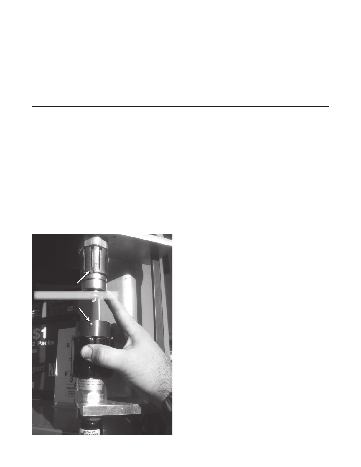
BREAKAWAY REATTACHMENT PROCEDURES
These VST reattachable breakaways can be reconnected in either
one of two methods:
METHOD 1: Use of the VST Breakaway Assembly Tool (VST-
BAT-200) with the appropriate reassembly plates for this breakaway.
1. Follow INSTALLATION PREPARATION steps 1 - 3.
2. Inspect both safety breakaway halves for damage that may
have occurred during separation. Include looking for external
damage to the product, damaged threads, damaged O-rings,
missing O-rings, proper placement of O-rings, etc. If damage is
detected, replace with new product.
3. Prior to reassembling, be sure the mating parts are undamaged
and clean.
4. Lightly lubricate ALL O-rings on mating connections with
petroleum jelly or other suitable lubricant.
FIGURE 2.
VST Breakaway Assembly Tool
VST Installation Procedure for
Phase II EVR Vacuum Assist
Safety Breakaway Devices
Part Number Series:
VST-HEVR-SBK;
VST-ISVR-SBK