Vulcan-Hart VPT User manual

OPERATOR’S MANUAL
VPT & VGT –Vulcan Push & Gear
Trolley
WARNING
DO NOT INSTALL, USE OR REPAIR THIS EQUIPMENT BEFORE
READING THIS MANUAL IN ITS ENTIERETY. FAILURE TO READ
AND FOLLOW THE INSTRUCTIONS DESCRIBED IN THIS MANUAL
COULD RESULT IN SERIOUS INJURY, DEATH AND/OR MATERIAL
DAMAGES

Vulcan Push & Gear Trolley 22020-02-05, rev1a
WARNING
All persons involved in using, inspecting, maintaining or
repairing this equipment must be thoroughly familiar with the
contents of this manual and follow the recommended
instructions and procedures to avoid injury or property damage.
WARNING
The equipment described in this manual is not designed to
lift or move people nor to lift or move loads over people and must
therefore not be used for such applications.
WARNING
Do not use this trolley in areas containing flammable
vapors, liquids, gasses or combustible dust or fibers. Do not use
this trolley in highly corrosive, abrasive, wet environments or in
temperatures below -10°C or above 50°C.
NOTICE
Please visit Vulcan’s website www.vulcanhoist.com for the
latest manual version or any other questions regarding the
equipment.

Vulcan Push & Gear Trolley 32020-02-05, rev1a
Safety and Warnings
Dangerous Practices to be Avoided
DO NOT use the trolley before reading the manual
DO NOT let an unqualified person use or repair the trolley
DO NOT exceed the rated capacity of the trolley
DO NOT use the trolley to grab, secure or lift the load
DO NOT use as a “below-the-hook” lifting device
DO NOT install trolley on beams of unknown capacity
DO NOT use the trolley in temperatures below -10°C or above
50°C
DO NOT use a damaged or malfunctioning trolley
DO NOT lift people nor carry loads over people
DO NOT stay in the “fall zone” when lifting a load
DO NOT lift if the trolley is not firmly tightened and adjusted on
the beam width with the necessary clearance
DO NOT lift unbalanced loads or loads that are not centered
DO NOT leave the load supported by the trolley unattended
DO NOT shock load or side load
DO NOT allow the load to swing
DO NOT allow a welding electrode to touch the beam trolley
DO NOT use the trolley as ground for welding
DO NOT remove or obscure labels
DO NOT use if nameplate or safety and warning labels are
missing or illegible
WARNING
Use the trolley ONLY to attach or suspend a load
underneath a fixed, stationary and rated for that purpose beam.
DO NOT use the trolley to grab, secure or lift the load. The
trolley is not designed as a “below-the-hook” lifting device and
must not be used as one.

Vulcan Push & Gear Trolley 42020-02-05, rev1a
WARNING
DO NOT attempt to modify this equipment or use it in a
manner different than described in this manual. Use only Vulcan
authorized replacement parts in the service and maintenance of
this equipment. Failure to comply with the above limitations will
void the warranty and may result in property damage, injury or
death.
Installation
Installation Procedures
1
Measure the width of the runway beam
2
Loosen the hex nuts on the stay bolts and remove the side
plate
3
Adjust the width of the trolley to match the beam width by
using the appropriate number of washers to spread apart
the side plates
4
Leave a slight clearance of about 1/8 inch between the
edge of the beam flange and the wheel flange
5
Make sure the suspension plate is centered and you have
equal number of washers on each side of it
6
Put the remaining washers on the outside of the side
plates. On gear trolleys, the equalizer pin must be offset as
to not interfere with the chain wheel. Do so by putting more
washers on the side opposite to the chain wheel
7
Reassemble the trolley on the beam and tighten slightly by
hand
8
Make sure all wheels are in contact with the beam flange
9
Tighten the hex nuts to the torque specified in the table
below
10
Install stoppers on the runway beam or other means of
preventing the trolley from rolling off unintentionally

Vulcan Push & Gear Trolley 52020-02-05, rev1a
Push model
Gear model
Stay bolt tightening torque
Nm (ft-lb)
VPT1/2T
VGT1/2T
138 (102)
VPT1T
VGT1T
138 (102)
VPT1.5T
VGT1.5T
138 (102)
VPT2T
VGT2T
239 (176)
VPT3T
VGT3T
239 (176)
VPT5T
VGT5T
475 (350)
WARNING
DO NOT use the trolley unless the load plate is centered.

Vulcan Push & Gear Trolley 62020-02-05, rev1a
ATTENTION
When installing the trolley on curved beams, orient trolley
with the gear wheels and the chain wheel on the outside of the
curve.
Refer to the table below for the minimum radii of
curvature compatible with each model as measured on the inside
of the curved beam.
Push model
Gear model
Minimum radius of curvature (in)
VPT1/2T
VGT1/2T
32
VPT1T
VGT1T
40
VPT1.5T
VGT1.5T
44
VPT2T
VGT2T
48
VPT3T
VGT3T
60
VPT5T
VGT5T
60

Vulcan Push & Gear Trolley 72020-02-05, rev1a
Operation
Operation Procedures
1
Prior to lifting, make sure the lift can be performed safely
and the lift path is clear
2
Ensure the beam is of suitable capacity for the load and
will not be damaged by the trolley rolling on the flange
3
Make sure the beam is fitted with stops at both ends to
prevent the trolley from rolling off
4
Make sure the load is properly centered below the trolley
5
Verify that all lifting devices used (including the trolley) are
properly fastened and of suitable working load limit
6
While performing the lift, do not let people to stay in or
cross the “fall zone” under the trolley
7
While performing the lift, do not allow the load to swing or
to move briskly
8
If using a push trolley, push the load from behind to move it
9
If using a gear trolley, steadily pull down on the hand chain
to move the load
10
At the end of the travel path slow down the load gently and
do not allow the trolley to hit the stoppers
WARNING
NEVER stay or pass through the “fall zone” under the
trolley.
ALWAYS keep your hands and feet away from the “fall
zone” under the trolley.

Vulcan Push & Gear Trolley 82020-02-05, rev1a
Inspection and Maintenance
ATTENTION
The trolley must be inspected by the operator daily. If any
deficiencies are noted, stop using the trolley until it is repaired or
replaced.
Suggested Daily Inspection List
1
Check for cracks or distortions in the structural frame,
welds or mechanical components
2
Check for loose or missing fasteners or other components
3
Check if trolley rolls smoothly
4
Check for signs of heat damage or weld splatter
5
Check for excessive wear on load bearing parts like, but not
limited to the wheels, the suspension pin, the thread, etc.
6
Make sure the nameplate and the warning labels are
present and legible
ATTENTION
A qualified person must inspect regularly and in depth the
trolley and its components to ensure the equipment is safe for
use. These inspections may vary in frequency and detail
according to the intensity of the equipment use but must include
at least the daily inspection procedure.
The user is responsible for keeping dated records of all
periodic inspections and maintenance procedures as means of
continuously monitoring the condition of the equipment.

Vulcan Push & Gear Trolley 92020-02-05, rev1a
Suggested Inspection Frequency
Initial
Initial installation, re-installation, altered,
repaired or modified equipment
Functional
Beginning of each shift
Frequent
Normal service –monthly
Heavy service –weekly to monthly
Severe service –daily to weekly
Periodic
Normal service –yearly
Heavy service –semi-annually
Severe service - quarterly
ATTENTION
Keep the moving components clean and well lubricated to
protect against premature wear.

Vulcan Push & Gear Trolley 10 2020-02-05, rev1a

Vulcan Push & Gear Trolley 11 2020-02-05, rev1a
Push
model
Gear
model
WLL
(lbf)
Weight1
(lbs)
A
(in)
B
(in)
C
(in)
D
(in)
E
(in)
F
(in)
G
(in)
H
(in)
L2
(ft)
R3
(in)
VPT1/2T
VGT1/2T
1100
16 (25)
8.6
1.26
3.7
2.8
1.0
2.50 –6.00
.82
10.0
10
32
VPT1T
VGT1T
2200
23 (34)
9.4
1.38
3.8
3.8
1.0
3.00 –5.50
.91
10.0
40
VPT1.5T
VGT1.5T
3300
29 (40)
10.2
1.57
4.2
3.8
1.1
3.00 –5.50
1.17
11.0
44
VPT2T
VGT2T
4400
45 (58)
12.2
1.77
5.0
4.2
1.3
3.38 –6.50
1.16
11.5
48
VPT3T
VGT3T
6600
64 (78)
14.3
2.20
5.1
4.2
1.4
3.94 –6.50
1.20
12.0
60
VPT5T
VGT5T
11000
111 (124)
15.0
2.56
5.9
5.5
3.0
4.50 –7.25
1.38
13.8
60
1
Push trolley weight (Gear trolley weight with standard chain length)
2
Standard length for gear trolleys. Custom lengths available on demand
3
Minimum beam radius of curvature

Vulcan Push & Gear Trolley 12 2020-02-05, rev1a
VPT1/2T
VPT1T
VPT1.5T
VPT2T
VPT3T
VPT5T

Vulcan Push & Gear Trolley 13 2020-02-05, rev1a
Item
Description
VPT1/2T
VPT1T
VPT1.5T
VPT2T
VPT3T
VPT5T
1
Plain wheel asm
4
4
4
4
4
4
3
Wheel pin
-
-
-
-
-
4
6
Stay bolt
1
2
2
2
2
2
7
Stay pipe
2
4
4
4
4
4
8
Plain-side plate
2
2
2
2
2
2
11
Adjustable collar
34
68
78
48
38
34
13
Hanging plate
1
1
1
1
1
1
101
Name plate
1
1
1
1
1
1
104
Retaining ring
4
4
4
4
4
4
105
Wheel pin nut
-
-
-
-
-
4
108
Stay bolt nut
2
4
4
4
4
4
109
Spring washer
2
4
4
4
4
4
Vulcan Push & Gear Trolley 14 2020-02-05, rev1a
VGT1/2T
VGT1T
VGT1.5T
VGT2T
VGT3T
VGT5T

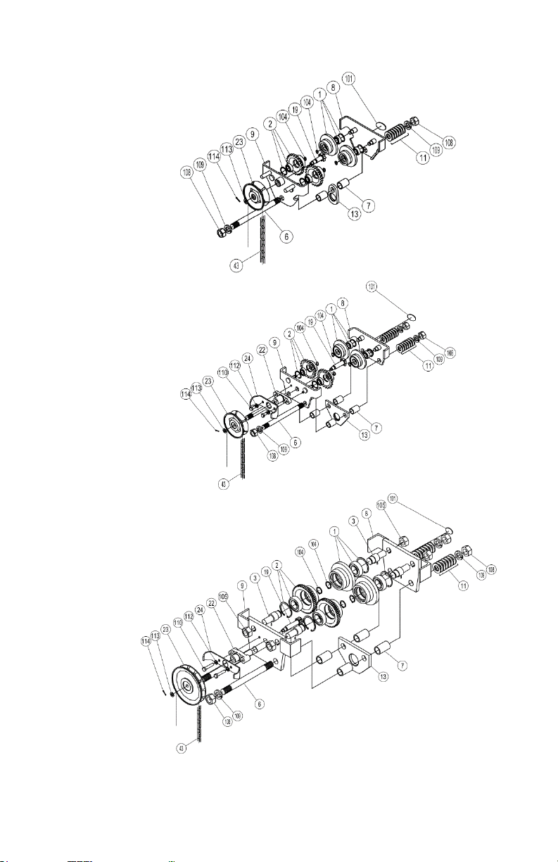
Vulcan Push & Gear Trolley 15 2020-02-05, rev1a
Item
Description
VGT1/2T
VGT1T
VGT1.5T
VGT2T
VGT3T
VGT5T
1
Plain wheel asm
2
2
2
2
2
2
2
Gear wheel asm
2
2
2
2
2
2
3
Wheel pin
-
-
-
-
-
4
6
Stay bolt
1
2
2
2
2
2
7
Stay pipe
2
4
4
4
4
4
8
Plain-side plate
1
1
1
1
1
1
9
Gear-side plate
1
1
1
1
1
1
11
Adjustable collar
34
68
78
48
38
34
13
Hanging plate
1
1
1
1
1
1
19
Pinion shaft
1
1
1
1
1
1
22
Pinion shaft metal
-
1
1
1
1
1
23
Hand wheel
1
1
1
1
1
1
24
Hand chain guide
-
1
1
1
1
1
43
Hand chain
1
1
1
1
1
1
101
Name plate
1
1
1
1
1
1
104
Retaining ring
4
4
4
4
4
4
105
Wheel pin nut
-
-
-
-
-
4
108
Stay bolt nut
2
4
4
4
4
4
109
Spring washer
2
4
4
4
4
4
110
Pinion shaft bolt
-
2
2
2
2
2
112
Spring washer
-
2
2
2
2
2
113
Plain washer
1
1
1
1
1
1
114
Split pin
1
1
1
1
1
1

This manual suits for next models
1
Table of contents
Other Vulcan-Hart Lifting System manuals

Popular Lifting System manuals by other brands


Nibotechnics
Nibotechnics Autolift electric installation instructions

John Bean
John Bean JLT4500S manual

Dhollandia
Dhollandia DH-LSP.07 installation manual

morse
morse 400AM-60 Assembly & operators manual

Motorline professional
Motorline professional CHAINLIFT User& installer's manual

Bishamon
Bishamon X Series Operation and service manual