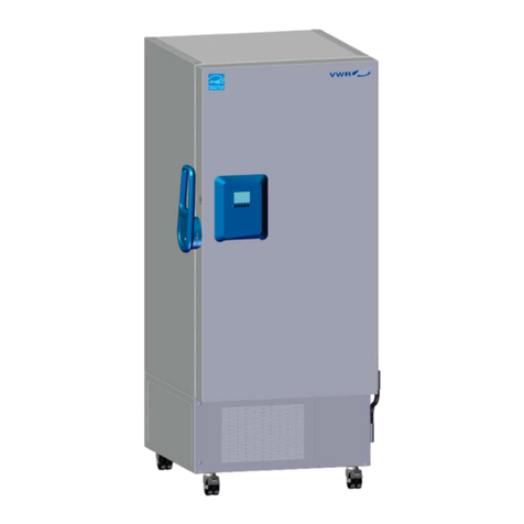
Model 5700 Series vVWR International
Table of Contents
Installation and Start-Up . . . . . . . . . . . . . . . . . . . . . . . . . . . . . . . . . . . . . .1-1
Operation of the Keypad . . . . . . . . . . . . . . . . . . . . . . . . . . . . . . . . . .1-3
Control Panel Keys, Displays & Indicators . . . . . . . . . . . . . . . . . . . .1-3
Remote Alarm Contacts . . . . . . . . . . . . . . . . . . . . . . . . . . . . . . . . .1-4
Freezer Installation . . . . . . . . . . . . . . . . . . . . . . . . . . . . . . . . . . . . . . .1-3
Choose the Location . . . . . . . . . . . . . . . . . . . . . . . . . . . . . . . . . . . .1-4
Shelf Installation . . . . . . . . . . . . . . . . . . . . . . . . . . . . . . . . . . . . . . .1-4
Wall Bumper Installation . . . . . . . . . . . . . . . . . . . . . . . . . . . . . . . .1-4
Electrical Power Connection . . . . . . . . . . . . . . . . . . . . . . . . . . . . . .1-5
Power Cord Attachment . . . . . . . . . . . . . . . . . . . . . . . . . . . . . . . . .1-5
Freezer Start-Up . . . . . . . . . . . . . . . . . . . . . . . . . . . . . . . . . . . . . . . . .1-5
Set the Operating Temperature . . . . . . . . . . . . . . . . . . . . . . . . . . . .1-6
Set the Low Temperature Alarm . . . . . . . . . . . . . . . . . . . . . . . . . . .1-7
Run Mode . . . . . . . . . . . . . . . . . . . . . . . . . . . . . . . . . . . . . . . . . . . . .1-7
Calibrate . . . . . . . . . . . . . . . . . . . . . . . . . . . . . . . . . . . . . . . . . . . . . . . . . . . .2-1
Calibrate the Control Probe . . . . . . . . . . . . . . . . . . . . . . . . . . . . . . . .2-1
Alarms . . . . . . . . . . . . . . . . . . . . . . . . . . . . . . . . . . . . . . . . . . . . . . . . . . . . . .3-1
High Stage System Failure . . . . . . . . . . . . . . . . . . . . . . . . . . . . . . . . .3-2
Probe Failure Alarm . . . . . . . . . . . . . . . . . . . . . . . . . . . . . . . . . . . . . .3-2
Maintenance . . . . . . . . . . . . . . . . . . . . . . . . . . . . . . . . . . . . . . . . . . . . . . . .4-1
Clean the Air Filter . . . . . . . . . . . . . . . . . . . . . . . . . . . . . . . . . . . . . .4-1
Clean the Condenser . . . . . . . . . . . . . . . . . . . . . . . . . . . . . . . . . . . . .4-1
Clean the Water-cooled Condenser . . . . . . . . . . . . . . . . . . . . . . . . .4-2
Clean the Vacuum Relief Port . . . . . . . . . . . . . . . . . . . . . . . . . . . . . .4-3
Clean the Door Gasket . . . . . . . . . . . . . . . . . . . . . . . . . . . . . . . . . . .4-3
Defrost the Chamber . . . . . . . . . . . . . . . . . . . . . . . . . . . . . . . . . . . . .4-3
Prepare the Unit for Storage . . . . . . . . . . . . . . . . . . . . . . . . . . . . . . . .4-5
Replace the Battery(s) . . . . . . . . . . . . . . . . . . . . . . . . . . . . . . . . . . . . .4-5
Section 1
Section 2
Section 3
Section 4
