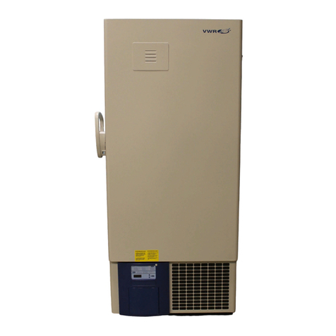
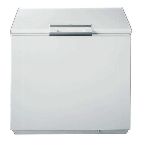
VWR 5720 Series Operating instructions

Model 5720 Series
-40C Lab Freezer
Operating and Maintenance Manual 7065722 Rev. 0

VWR International
MANUAL NUMBER 7065722
0 FR-2400 1/25/13 Release 8 - elec & refrig schematics, expl base dwg ccs
REV ECR/ECN DATE DESCRIPTION By
Preface
-40C Lab Freezer i
Model Capacity in Cubic Feet Voltage
5722 13 120
5727 13 230
5728 17 120
5729 17 230
Part
Number Description Quantity
34040 Key Ring 1
122005 Key 2
380520 Neoprene Cap 2
510016 1/4-20 x 5-1/2” Bolt 2
195763 Retaining Clip 1
370563 Remote Alarm Connector 1
Packing List
Models Covered
Important installer and user information: A redundant temperature
sensing device has been included in this ULT freezer. This device is a type
“T” thermocouple. For convenient access, the thermocouple (Figure 1-3)
terminates in an interconnect jack (Figure 1-5) behind the base front cover.
(May be located differently in chests. See Section 1.) It is strongly
recommended that this thermocouple be attached to a redundant 24 hour
7 day monitoring system with alarm capabilities. Connecting the sensor to
a monitoring and alarm system separate from the freezer provides the
utmost in product safety, should the integral system fail. s

VWR Internationalii -40C Lab Freezer
Preface
Important Read this instruction manual. Failure to read, understand and follow the instructions in this manual
may result in damage to the unit, injury to operating personnel, and poor equipment performance. s
Caution All internal adjustments and maintenance must be performed by qualified service personnel. s
Material in this manual is for information purposes only. The contents and the product it describes are subject to
change without notice. VWR International makes no representations or warranties with respect to this manual.
In no event shall VWR be held liable for any damages, direct or incidental, arising out of or related to the use of
this manual.
©2013 VWR International. All rights reserved.

VWR International -40C Lab Freezer iii
Preface
Important operating and/or maintenance instructions. Read the accompanying text carefully.
Potential electrical hazards. Only qualified persons should perform procedures associated with this
symbol.
Equipment being maintained or serviced must be turned off and locked off to prevent possible injury.
Hot surface(s) present which may cause burns to unprotected skin, or to materials which may be
damaged by elevated temperatures.
Marking of electrical and electronic equipment, which applies to electrical and electronic equipment
falling under the Directive 2002/96/EC (WEEE) and the equipment that has been put on the market
after 13 August 2005.
This product is required to comply with the European Union’s Waste Electrical & Electronic
Equipment (WEEE) Directive 2002/96/EC. It is marked with the WEEE symbol. VWR International
has contracted with one or more recycling/disposal companies in each EU Member State European
Country, and this product should be disposed of or recycled through them. Further information on
VWR’s compliance with this directive, the recyclers in your country and information on VWR
products will be available at www.vwrsp.com.
4Always use the proper protective equipment (clothing, gloves, goggles, etc.)
4Always dissipate extreme cold or heat and wear protective clothing.
4Always follow good hygiene practices.
4Each individual is responsible for his or her own safety.

VWR Internationaliv -40C Lab Freezer
Preface
Do You Need Information or Assistance on
VWR Scientific Products?
The VWR can provide information on pricing and give you quotations. We can take
your order and provide delivery information on major equipment items or make arrangements to have your
local sales representative contact your. Our products are listed on the internet and we can be contacted
through our Internet home page.
1-800-932-5000 VWR, Toll Free, US
http://www.vwrsp.com Internet Worldwide Web Home page
The VWR can supply technical information about proper
setup, operation or troubleshooting of your equipment. We can fill your needs for replacement parts or
provide you with on-site service. We can also provide you with a quotation on our Extended Maintenance
Program for your Forma products.
Whatever VWR or Forma products you need or use, we will be happy to discuss your applications.
If you are experiencing technical problems, working together, we will help you locate the problem and,
chances are, correct it yourself...over the telephone without a service call.
When more extensive service is necessary, we will assist you with direct factory trained
technicians or a qualified service organization for on-the-spot repair. If your service need is covered by the
VWR Brand warranty, we will arrange for the unit to be repaired at our expense and to your satisfaction.
Regardless of your needs, VWR support by Thermo's professional telephone technicians is
available to assist you Monday through Friday from 8:00a.m. to 6:30 p.m. Eastern Time. Please call or fax us
at:
If you wish to write, our mailing address is:
Thermo 'JTIFSScientific
401 Millcreek Road, Box 649
Marietta, OH 45750
Sales Group
Product Service Group at Thermo
1-740-373-4763 Direct
1-800-438-4851 Technical Services Toll Free, U.S. and Canada
1-740-373-4189 FAX
Http://www.thermo.com Internet Worldwide Web Home Page
Service E-Mail Addressservice.led.marietta@thermofisher.com

-40C Lab Freezer vVWR International
Table of Contents
Installation and Start-Up . . . . . . . . . . . . . . . . . . . . . . . . . . . . . . . . . . . . . .1-1
Control Panel Keys, Displays & Indicators . . . . . . . . . . . . . . . . . . . .1-2
Keypad Operation . . . . . . . . . . . . . . . . . . . . . . . . . . . . . . . . . . . . . . .1-3
Freezer Installation . . . . . . . . . . . . . . . . . . . . . . . . . . . . . . . . . . . . . . .1-3
Choose the Location . . . . . . . . . . . . . . . . . . . . . . . . . . . . . . . . . . . .1-3
Wall Bumper Installation . . . . . . . . . . . . . . . . . . . . . . . . . . . . . . . .1-4
Shelf Installation . . . . . . . . . . . . . . . . . . . . . . . . . . . . . . . . . . . . . . .1-4
Remote Alarm Contacts . . . . . . . . . . . . . . . . . . . . . . . . . . . . . . . . .1-4
Attach the Power Cord . . . . . . . . . . . . . . . . . . . . . . . . . . . . . . . . . .1-5
Connect the Unit to Electrical Power . . . . . . . . . . . . . . . . . . . . . . .1-5
Freezer Start-Up . . . . . . . . . . . . . . . . . . . . . . . . . . . . . . . . . . . . . . . . .1-5
Set Operating Temperature . . . . . . . . . . . . . . . . . . . . . . . . . . . . . . .1-6
Set High Temperature Alarm . . . . . . . . . . . . . . . . . . . . . . . . . . . . . .1-6
Set Low Temperature Alarm . . . . . . . . . . . . . . . . . . . . . . . . . . . . . .1-7
Run Mode . . . . . . . . . . . . . . . . . . . . . . . . . . . . . . . . . . . . . . . . . . . . .1-7
Calibrate . . . . . . . . . . . . . . . . . . . . . . . . . . . . . . . . . . . . . . . . . . . . . . . . . . . .2-1
Calibrate the Control Probe . . . . . . . . . . . . . . . . . . . . . . . . . . . . . . . .2-1
Alarms . . . . . . . . . . . . . . . . . . . . . . . . . . . . . . . . . . . . . . . . . . . . . . . . . . . . . .3-1
Probe Failure Alarm . . . . . . . . . . . . . . . . . . . . . . . . . . . . . . . . . . . . . .3-1
Error Messages . . . . . . . . . . . . . . . . . . . . . . . . . . . . . . . . . . . . . . . . . .3-2
Maintenance . . . . . . . . . . . . . . . . . . . . . . . . . . . . . . . . . . . . . . . . . . . . . . . .4-1
Clean the Air Filter . . . . . . . . . . . . . . . . . . . . . . . . . . . . . . . . . . . . . .4-1
Clean the Condenser . . . . . . . . . . . . . . . . . . . . . . . . . . . . . . . . . . . . .4-1
Defrost the Chamber . . . . . . . . . . . . . . . . . . . . . . . . . . . . . . . . . . . . .4-2
Clean the Door Gasket . . . . . . . . . . . . . . . . . . . . . . . . . . . . . . . . . . .4-2
Clean the Vacuum Relief Port . . . . . . . . . . . . . . . . . . . . . . . . . . . . . .4-2
Replace the Battery(s) . . . . . . . . . . . . . . . . . . . . . . . . . . . . . . . . . . . . .4-4
Prepare the Unit for Storage . . . . . . . . . . . . . . . . . . . . . . . . . . . . . . . .4-4
Preventive Maintenance . . . . . . . . . . . . . . . . . . . . . . . . . . . . . . . . . . .4-5
Section 1
Section 2
Section 3
Section 4
vi -40C Lab Freezer VWR International
Factory Installed Options . . . . . . . . . . . . . . . . . . . . . . . . . . . . . . . . . . . . . .5-1
Back Up System (BUS) . . . . . . . . . . . . . . . . . . . . . . . . . . . . . . . . . . .5-1
Install the Vent Stack, Solenoid & Injection Ass’y . . . . . . . . . . . . . .5-2
Install the Temperature Probe . . . . . . . . . . . . . . . . . . . . . . . . . . . . .5-3
Connect the Probe/Solenoid Harness . . . . . . . . . . . . . . . . . . . . . . .5-4
BUS Control Panel . . . . . . . . . . . . . . . . . . . . . . . . . . . . . . . . . . . . .5-5
Configure the BUS . . . . . . . . . . . . . . . . . . . . . . . . . . . . . . . . . . . .5-5
Set the BUS Set Point . . . . . . . . . . . . . . . . . . . . . . . . . . . . . . . . . . .5-6
Test the BUS . . . . . . . . . . . . . . . . . . . . . . . . . . . . . . . . . . . . . . . . . .5-6
Clean the Vent Stack . . . . . . . . . . . . . . . . . . . . . . . . . . . . . . . . . . . .5-6
Disconnect Fitting Assembly & Transfer Hose . . . . . . . . . . . . . . . .5-7
Chart Recorder . . . . . . . . . . . . . . . . . . . . . . . . . . . . . . . . . . . . . . . . . .5-7
Install the Chart Paper . . . . . . . . . . . . . . . . . . . . . . . . . . . . . . . . . .5-7
Change the Programmed Temperature Range . . . . . . . . . . . . . . . . .5-8
Calibrate the Recorder . . . . . . . . . . . . . . . . . . . . . . . . . . . . . . . . . .5-8
Datalogger . . . . . . . . . . . . . . . . . . . . . . . . . . . . . . . . . . . . . . . . . . . . .5-9
Five Inner Doors . . . . . . . . . . . . . . . . . . . . . . . . . . . . . . . . . . . . . . . .5-9
Specifications . . . . . . . . . . . . . . . . . . . . . . . . . . . . . . . . . . . . . . . . . . . . . . .6-1
Exploded Parts Drawings . . . . . . . . . . . . . . . . . . . . . . . . . . . . . . . . . . . . .7-1
Refrigeration Schematics . . . . . . . . . . . . . . . . . . . . . . . . . . . . . . . . . . . . .8-1
Electrical Schematics . . . . . . . . . . . . . . . . . . . . . . . . . . . . . . . . . . . . . . . .9-1
Warranty . . . . . . . . . . . . . . . . . . . . . . . . . . . . . . . . . . . . . . . . . . . . . . . . . . .10-1
Handling Liquid Nitrogen . . . . . . . . . . . . . . . . . . . . . . . . . . . . . . . . . . . . .11-1
Introduction . . . . . . . . . . . . . . . . . . . . . . . . . . . . . . . . . . . . . . . . . . .11-2
Handling Liquid CO2. . . . . . . . . . . . . . . . . . . . . . . . . . . . . . . . . . . . . . . . .11-4
First Aid . . . . . . . . . . . . . . . . . . . . . . . . . . . . . . . . . . . . . . . . . . . . . .11-5
Table of Contents
Section 5
Section 6
Section 8
Section 7
Section 9
Section 10
Appendix A

-40C Lab Freezer 1-1VWR International
Section 1 Installation and Start-Up
Vacuum relief
cover plate
Control panel
Optional back-up
system controls
Temperature
recorder (optional)
Vacuum Relief
Port
Chamber Probe
Cover
Optional Back-up
System Connections
Power Switch
(mains
disconnect)
Power Inlet
Remote Alarm
Contacts
Wall Bumper
(pre-tapped holes)
Shelf
Bracket
Sealant
(Caution: This is a critical seal.
Seal must be maintained.)
Optional - Recorder Probe/Datalogger Probe
Control RTD/Redundant Type T
Thermocouple Probe
Optional Miscellaneous Accessories Probe
Figure 1-1
• Control Panel - keypad, displays and indicators.
• BUS (optional Back Up System) panel.
• Optional temperature recorder - 7 day, one pen
or Datalogger.
• Vacuum relief port cover plate.
Figure 1-2
• Remote alarm contacts.
• Power Inlet for power cord connection.
• Optional BUS connections for probe and sole-
noid.
• Power Switch (mains disconnect).
Figures 1-3 and 1-4
• Vacuum relief port - pressure equalization port.
• Probe cover - houses control, optional recorder,
datalogger, or miscellaneous accessory probes.
Figure 1-4. Vacuum Relief and Probe Cover Location
Figure 1-1. Front View
Figure 1-2. Rear View
Figure 1-3. Chamber Probe

1-2 -40C Lab Freezer VWR International
Section 1
Installation and Start-Up
Figure 1-5. Battery and Switch Locations
• Battery mounting bracket(s)
• Battery power switch (freezer and BUS)
• Freezer battery
• Optional BUS battery
• Freezer filter location
• Temperature Display - Displays temperature in degrees Celsius.
• Mode Select Switch - Used to select Run, Set Temperature, Set High
Alarm, Set Low Alarm, Calibrate, Backup.
• Alarm Indicator - Light pulses on/off during a cabinet alarm condition.
• Mute - Silences the audible alarm.
• Alarm Panel - indicates the current alarm condition.
• Up and Down Arrows - Increases or decreases values, toggles between
choices.
• Enter - Stores the value into memory.
Control Panel Keys,
Displays & Indicators
O
Battery power
switch To
remove filter
Thermocouple
interconnect jack
Battery mounting
bracket
Freezer battery
and optional BUS battery
Temperature
Display
Mode
Key
Alarm
Indicator
Silence
Key
Alarm
Panel
Up and Down
Arrows
Enter Key
Figure 1-6. Control Panel

-40C Lab Freezer 1-3VWR International
Section 1
Installation and Start-Up
Freezer Installation
The Model 5700 Series freezer has five basic modes which allow freezer
setup and operation. Press the Mode key to scroll through the mode
selections.
Up Arrow: Increases or toggles the parameter value.
Enter: Must press Enter key to save to memory all changed values.
Down Arrow: Decreases or toggles the parameter value.
Mute Key: Press to silence the audible alarm. See Section 4 for alarm
ringback times.
Caution If tipped more than 45°, allow the unit to set upright for 24 hours
before start up. s
To remove the freezer from the pallet, use the 7/16" wrench to remove all
the bolts securing the shipping bracket to the pallet.
Remove the shipping bracket. Remove the ramp boards from the pallet
and place the slotted end over the ramp brackets on the pallet. The
support blocks on the ramps will be facing down. Before moving the
freezer, make sure the casters are unlocked and moving freely. Align the
caster with the ramp boards. Use adequate personnel to roll the freezer off
the pallet.
The freezer can be easily pushed to the desired approved location,
described following. If necessary, the doors and lower front panel may be
opened to move the unit through tight openings. When the freezer is in
position, set the front caster brakes.
Caution The freezer must not be moved with the product load inside. s
Caution For proper ventilation and airflow, a minimum clearance of 5” at
the rear and top and a clearance of 8” on the side of the freezer is required.
Allow adequate space in the front of the freezer for door opening. s
Locate the freezer on a firm, level surface in an area with an ambient
temperature between 18°C and 32°C. Provide ample room to reach the
mains disconnect switch (power switch) located on the rear of the freezer.
Keypad Operation
Choose the Location

The parts bag, located inside the cabinet, contains the following parts.
Install the bolts into the pre-tapped holes on the back of the compressor
section. Install a neoprene cap on each bolt. Refer to Figure 1-2 for the
locations of the pre-tapped holes.
Install the shelf clips into the shelf pilasters (front and back) at the desired
shelf level. Install the shelves in the cabinet onto the clips.
Note On units having the optional 5 inner door option, refer to the
instructions accompanying the inner door kit. s
See Figure 1-2 for the location of the remote alarm contacts. The remote
alarm connector is located in the parts bag provided with the manual. It
must be installed if connecting the freezer to an alarm system. After
installing the wiring from the alarm system to
the connector, install the connector to the
freezer microboard and secure with the two
screws provided. The remote alarm provides a
NO (normally open) output, a NC (normally
closed) output and COM (common). The
contacts will trip on a power outage, high
temperature alarm or low temperature alarm.
They will also trip on control probe and
microboard failures. Figure 1-7 shows the
remote contacts in alarm state.
1-4 -40C Lab Freezer VWR International
Section 1
Installation and Start-Up
Wall Bumper Installation
Quantity Stock # Description Purpose
2510016 1/4-20 x 5-1/2” Bolt Wall Bumper
2380520 Neoprene Cap Cap Protector
Figure 1-7. Contacts
IMPORTANT USER INFORMATION
Caution! Stored product should be protected
by a redundant 24 hour/day monitoring
system with alarm capability. An interconnect
jack and thermocouple are installed
for centralized monitoring should on-board
system fail.
Shelf Installation
Remote Alarm Contacts

Insert the power cord into the power inlet module. Place the retaining
bracket (P/N 195763) over the conector. Tighten retaining screws to
secure.
Note See the serial tag on the side of the unit for electrical specifications or
refer to the electrical schematics in this manual. s
The freezer should be operated on a dedicated grounded circuit. Check the
voltage rating on the serial tag of the unit and compare it with the outlet
voltage. Then, with the power switch turned off, plug the line cord into
the wall outlet.
First turn on the freezer power switch. Then open the lower front door by
grasping the bottom left corner. Locate the battery switch (Figure 1-5) and
turn it to Standby mode ( ). During initial freezer start-up, the system
battery may require charging and the Low Battery indicator may
illuminate.
Caution Ensure the battery switch is turned to Standby mode ( ). The
rechargeable batteries require 36 hours to charge at initial start-up. A “Low
Battery” alarm may occur until the batteries are fully charged. Should a
power failure occur during the initial start-up period, the electronics will
have limited operation. s
With the freezer properly installed and connected to power, system set
points can be entered. The following set points can be entered in Settings
mode: Control temperature, high
temperature alarm set point, low
temperature alarm set point, and
(optional) BUS set point. Default
settings are shown at right.
-40C Lab Freezer 1-5VWR International
Section 1
Installation and Start-Up
Attach the Power Cord
Figure 1-8. Power Cord
Connect the Unit to
Electrical Power
Freezer Start-Up
Control Set Point -40°C
High Temperature Alarm -30°C
Low temperature alarm -50°C
Optional BUS Set Point -30C

The freezer has an operating temperature range of -10°C to -40°C,
depending on ambient temperature. The freezer is shipped from the factory
with a temperature set point of -40°C. To change the operating
temperature set point:
1. Press the Mode key until the Set Temperature indicator lights.
2. Press the up/down arrow key until the desired temperature set point is
displayed.
3. Press Enter to save the set point.
4. Press the Mode key until the Run indicator lights for Run mode
If no keys are pressed, the freezer will automatically return to RUN mode
after 5 minutes.
Caution If the set point is changed and the low and high temperature
alarms are set 10° from the set point, the alarm set points will be adjusted
automatically to maintain a distance of at least 10° from set point. s
The high temperature alarm will activate an audible/visual warning when
the freezer chamber temperature has reached or exceeded the high
temperature alarm set point. To set the high temperature alarm set point:
1. Press the Mode key until the Set High Alarm indicator lights.
2. Press the up or down arrow key until the desired high temperature
alarm set point is displayed.
3. Press Enter to save the setting.
4. Press the Mode key until the Run indicator lights for Run mode
If no control keys are pressed, the freezer will automatically return to RUN
mode after 5 minutes.
Note The high alarm set point must be set at least 5°C from the control
set point. s
Caution At initial start-up, the high temperature alarm is disabled until the
cabinet reaches set point or 12 hours elapse. s
1-6 -40C Lab Freezer VWR International
Section 1
Installation and Start-Up
Set Operating
Temperature
Set High Temperature
Alarm

The low temperature alarm will activate an audible/visual warning when
the freezer chamber temperature has reached or decreased below the low
temperature alarm set point. To set the low temperature alarm set point:
1. Press the Mode key until the Set Low Alarm indicator lights.
2. Press the up or down arrow key until the desired low temperature
alarm set point is displayed.
3. Press Enter to save the setting.
4. Press the Mode key until the Run indicator lights for Run mode
If no control keys are pressed, the freezer will automatically return to RUN
mode after 5 minutes.
Note The low alarm set point must be set at least 5°C from the control set
point. s
Run is the default mode for the freezer. This mode displays the cabinet
temperature on the temperature display under normal operating
conditions.
-40C Lab Freezer 1-7VWR International
Section 1
Installation and Start-Up
Set Low Temperature
Alarm
Run Mode


-40C Lab Freezer 2-1VWR International
Section 2 Calibrate
Once the freezer has stabilized, the control probe may need to be
calibrated. Calibration frequency is dependent on use, ambient conditions
and accuracy required. A good laboratory practice would require at least an
annual calibration check. On new installations, all parameters should be
checked after the stabilization period.
Caution Before making any calibration or adjustments to the unit, it is
imperative that all reference instruments be properly calibrated. s
Plug a type T thermocouple reader into the receptacle located inside the
lower door (see Figure 1-5). Compare the control temperature set point to
the temperature of the measuring device.
1. Press the Mode key until the Calibrate indicator lights.
2. Press up/down arrow to match the display to calibrated instrument.
3. Press Enter to store calibration.
4. Press the Mode key to return to Run mode.
Temperature Stabilization Periods
Startup - Allow 12 hours for the temperature in the cabinet to stabilize
before proceeding.
Already Operating - Allow at least 2 hours after the display reaches set
point for temperature to stabilize before proceeding.
Caution During calibration, the temperature display will be unavailable. s
If no keys are pressed for approximately five minutes while in calibration
mode, the system will reset to Run mode.
Calibrate the Control
Probe


-40C Lab Freezer 3-1VWR International
Section 3 Alarms
The Model 5700 Series freezer alarms are displayed on the freezer control
panel. When an alarm is active, the indicator next to the alarm description
will light and there will be an audible alarm. Press the Mute key to disable
the audible alarm for the ringback period. The visual alarm will continue
until the freezer returns to a normal condition. The alarms are momentary
alarms only. When an alarm condition occurs and then returns to normal,
the freezer automatically clears the alarm condition and the message center.
The microprocessor in Model 5700 Series freezers continually scans all
probes including the control probe and condenser probe to ensure that
they are operating properly. Should an error be detected, the "Probe
Failure" alarm will occur as described above. If an error is detected with
the control probe, the compressor will run continuously. As a result, the
cabinet temperature will decrease until it reaches the lowest temperature
that the refrigeration system can maintain. If an error is detected with the
condenser probe, there is no impact on the performance of the freezer;
however, the hot condenser alarm may also occur. Contact the VWR
Service Department or your local distributor.
Description Delay Ringback Relay
Power Failure 1 min. 15 min. Yes
High Temperature Alarm 1 min. 15 min. Yes
Low Temperature Alarm 1 min. 15 min. Yes
Probe Failure 1 min. 15 min. No
Door Open 1 min. 15 min. No
Wrong Power 0 min. none Yes
Low Battery* 1 min. 12 hours No
Low BUS Battery (optional) 1 min. 15 min. No
Hot Condenser 1 min. none No
Micro Board Failure 0 min. 15 min. Yes
All alarm delays and ringback times are ±30 seconds.
*The automatic battery test runs immediately on start-up, then every 8 hours there-
after.
Probe Failure Alarm

3-2 -40C Lab Freezer VWR International
Section 3
Alarms
Error Notes
Er00
Name: Improper model selected.
Description: Indicates that DIP SW3 has not selected a proper model or can’t be accessed properly.
Response: Display shows “Er00” and will not start-up until a proper model is selected. Contact Technical Services.
ErA1 This error condition will prevent peripherals (fans, compressors, etc.) from powering up with the incorrect voltage.
Name: Voltage/Frequency failure
Description: Indicates the measured RMS line voltage did not agree with the logic level sensed by the micros provided by the
installed high voltage PCB; or the measured RMS voltage is not within a tolerable range (<180VAC < 270 for 230VAC unit / <
85VAC < 160 for 115VAC unit); or the frequency measured over 10 cycles was not within a tolerable range (55 Hz < Freq < 70 Hz
for 60 Hz units / 40 Hz < Freq < 55 Hz for 50 Hz units)
Response: This condition is checked at power on reset and if it is active, the unit will NOT power up. The unit will indefinitely
display “Er_1” in the display and continue to monitor the frequency and voltage. Furthermore, the audible alarm will sound. Other
startup error messages may be displayed prior to this message; however, the system will stop the startup sequence for this condi-
tion.
ErA1 .. No pulses (zero crossings) detected to determine frequency (50 / 60 Hz)
ErC1 .. Frequency detected is below 50 Hz
Erd1 .. Frequency detected is above 60 Hz (Possible noise spikes on supply voltage)
ErE1 .. Unit is 230V and the voltage detected is below the low limit (180VRMS)
ErF1 .. Unit is 230V and the voltage detected is above the high limit (260VRMS)
Erg1 .. Unit is 115V and the voltage detected is below the low limit (85VRMS)
ErH1 .. Unit is 115V and the voltage detected is above the high limit (160VRMS)
ErC1
Erd1
ErE1
ErF1
Erg1
ErH1
Er02
Name: Control (Cabinet) Sensor Failure
Description: This condition indicates that the control sensor has failed to produce a valid reading for >12 consecutive reads (~60
seconds).
Response: The unit will stage both compressors on (if necessary) and the unit will attempt to head to bottom out. If the sensor
recovers, the system will begin to operate normally and respond to the temperature feedback. The remote alarm contacts will
become active. ‘Er02’ will be added to the main display queue and the last valid cabinet temperature value will not be displayed.

-40C Lab Freezer 3-3VWR International
Section 3
Alarms
Error (cont.) Notes
Er05
Name: Display Firmware Integrity Failure
Description: The display firmware has failed to pass its CRC CCITT checksum integrity test.
Response: The display performs this check at startup and the display board will fail to startup without any error indication if it
does not pass this at power on.
Er06
Name: Micro Firmware Integrity Failure
Description: The micro firmware has failed to pass its CRC CCITT checksum integrity test.
Response: This is checked at power on reset and the “Er06” will be displayed for ~10 seconds at startup if this condition
exists.
Er07
Name: Micro Fail - CS5521 SPI Failure / UISR Failure
Description: This condition indicates a micro board failure due to either the SPI bus is unable to communicate with the ADC
device or a UISR event caused the microcontroller to be in an unstable state.
Response: The unit will try to recover from this fault three times by a hardware reset of the micro board. In the event that the
system couldn’t rectify the issue, the following sequence of events will occur:
1. Remote alarm contacts will become active.
2. Buzzer will annunciate audibly and will have a ringback of 15 minutes.
3. “Seven segment” display will show “Er07”.
4. The compressor will activate.
5. The system will go to bottom out temperatures.
Er09
Name: Stuck Button
Description: This condition indicates that the display board has a stuck button.
Response: The Er09 will show on the display periodically.
Er11
Name: Condenser Probe Sensor Failure
Description: This condition indicates that the condenser probe sensor has failed to produce a valid reading for >12 consecutive
reads (~60 seconds).
Response: The display shows “Er11”.
dErr This is a general display error in which value being displayed can not be represented within characters provided.
(Four dashes)
---- in display
Name: Lost Communication
Description: Communication between the micro board and the display board has been lost. Under this condition, the visual
alarm flashes along with dashes in the temperature display (----). Contact Technical Services.
This manual suits for next models
4
Table of contents
Other VWR Freezer manuals

VWR
VWR VWR24086A User manual

VWR
VWR Avantor 352 Eco Premium User manual

VWR
VWR Avantor 352 Eco Premium Product information sheet

VWR
VWR 5700 Series Operating instructions

VWR
VWR SCBAF-1420 User manual

VWR
VWR VWRC0386A User manual

VWR
VWR SCUCBI-0420 User manual

VWR
VWR SCPMF-2020 User manual

VWR
VWR VWR24086A User manual

VWR
VWR 5700 Series Operating instructions