Vynckier MW TOOLS WD70 User manual

M1.1.WD70-WD100-WD170.NLFREN - 25042019
HANDLEIDING - MODE D’EMPLOI - MANUAL
WD70 (722316564)
WD100 (722316566)
WD170 (722316568)
Diesel verwarming
Chauffage diesel
Diesel heater
WD170
P.02 Gelieve te lezen en voor later gebruik bewaren
P.10 Veuillez lire et conserver pour consultation ultérieure
P.18 Please read and keep for future reference
FR
EN
NL
copyrighted document - all rights reserved by FBC

2
NL
M1.1.WD70-WD100-WD170.NLFREN - 25042019
Dit product is niet bedoeld voor gebruik als hoofdverwarming!
Lees deze handleiding aandachtig voordat u het apparaat gebruikt, en bewaar ze voor
toekomstig gebruik.
Aansprakelijkheid
De fabrikant behoudt zich het recht voor om na publicatie wijzigingen aan te brengen in specicaties, hoeveelheden,
afmetingen enz. om productie- of andere redenen.
Hoewel wij van mening zijn dat de informatie juist en volledig is, bieden wij geen garantie of verklaring voor een bepaald
doel. De informatie wordt te goeder trouw gegeven en het is duidelijk dat elk gebruik van het apparaat of de accessoires
in strijd met de instructies en waarschuwingen in dit document geheel naar eigen goeddunken en op eigen risico van de
gebruiker is.
Richtlijnen voor de verwijdering (EU)
Gooi dit product niet met huisvuil weg. Dit product moet afgevoerd worden in overeenstemming met de wetgeving inzake
afgedankte elektrische en elektronische apparatuur. Neem indien nodig contact op met de bevoegde autoriteiten, om na te
gaan welke voorzieningen in uw regio beschikbaar zijn voor de verwijdering van dit afval.
1 Veiligheidsvoorschriften
• Lees en volg alle instructies aandachtig. Bewaar de instructies in een veilige plaats, om deze op elk ogenblik te kunnen
raadplegen. Alleen mensen, die deze instructies gelezen hebben, mogen dit verwarmingstoestel assembleren, inschakelen,
instellen en gebruiken.
• Als de instructies in deze handleiding niet strikt opgevolgd worden, kan dit leiden tot brand of explosie, met als gevolg
materiële schade en ernstige of dodelijke letsels.
• Het onderhoud van het apparaat moet door een bevoegde technische dienst uitgevoerd worden.
• Draagbare niet geventileerde verwarmingstoestellen gebruiken lucht (zuurstof) uit de ruimte waarin ze gebruikt worden. De
toegevoerde lucht voor verbranding en ventilatie moet voldoende zijn. Zie de instructies.
• Bewaar of gebruik geen benzine of andere ontvlambare dampen of vloeistoffen in de nabijheid van dit apparaat of van
soortgelijke apparatuur.
• Gevaar voor brand, brandwonden, inademing en explosie. Bewaar brandstoffen zoals bouwmaterialen,
papier of karton op een veilige afstand van het verwarmingstoestel. Gebruik dit apparaat nooit in ruimten die vluchtige
of in de lucht zwevende brandstoffen bevatten of kunnen bevatten, of producten zoals benzine, oplosmiddelen, verf
verdunners, stofdeeltjes of onbekende chemicaliën.
• Verwarmingstoestellen met directe verbranding kunnen koolmonoxidevergiftiging (CO) veroorzaken bij onjuist gebruik,
bijvoorbeeld binnenshuis zonder luchtcirculatie of als ze niet goed functioneren. CO-vergiftiging kan de dood veroorzaken.
• Het niet in acht nemen van de veiligheidsvoorschriften en instructies, die bij dit apparaat meegeleverd worden, kan leiden
tot de dood, ernstige letsels, materiële schade door brand, explosie, brandwonden, verstikking, koolmonoxidevergiftiging
en/of elektrische schokken. Alleen personen die in staat zijn om deze instructies te begrijpen en te volgen, zijn bevoegd
om dit apparaat te bedienen of te onderhouden. Als u hulp nodig heeft, informatie zoals handleidingen, etiketten, enz.,
neem dan contact op met de fabrikant of uw verdeler.
Inhoud
1 Veiligheidsvoorschriften...........................................................................................................................................2
2 Omschrijving van het product ..................................................................................................................................3
3 Montage instructies.................................................................................................................................................4
4 Installatie...............................................................................................................................................................5
5 Bedieningsinstructies...............................................................................................................................................5
5.1 Inschakelen....................................................................................................................................................5
5.2 Manueel resetten/opnieuw starten ....................................................................................................................6
5.3 Uitschakelen...................................................................................................................................................6
6 Reiniging, onderhoud en opslag...............................................................................................................................7
7 Storingen oplossen .................................................................................................................................................9
8 Onderdelen......................................................................................................................................................... 26
9 Schakelschema .................................................................................................................................................... 29
10 EG conformiteitsverklaring ...................................................................................................................................30
copyrighted document - all rights reserved by FBC

3
NL
M1.1.WD70-WD100-WD170.NLFREN - 25042019
• Dit verwarmingstoestel is niet bedoeld voor gebruik in woningen of vrijetijdsvoertuigen.
• De vooruitgang is zeer heet tijdens het gebruik. Niet aanraken! Gevaar voor brandwonden.
Elektriciteit:
• De elektrische installatie waarop het apparaat aangesloten is moet voldoen aan de geldende wetgeving. De installatie
moet een aardlekschakelaar (RCCB) in het hoofdschakelbord hebben.
• Haal de stekker van het apparaat uit het stopcontact voordat u onderhoudswerkzaamheden uitvoert.
• Controleer altijd de voedingskabel voordat u het apparaat gebruikt. Deze mag niet gebogen, uitgerekt, geplet of
beschadigd zijn.
• De voedingskabel moet door een gekwaliceerde elektricien vervangen worden. Gebruik een originele voedingskabel met
een goedgekeurde 3-pins stekker.
2 Omschrijving van het product
Mobiele/draagbare directe verbranding diesel- of petroleumverwarming, met open verbrandingskamer.
Model WD70 WD100 WD170
Warmteafgifte* 20 kW 30 kW 50 kW
Luchtstroom 550 m³/h 720 m³/h 1100 m³/h
Type brandstof Diesel/Pétrole Diesel/Pétrole Diesel/Pétrole
Brandstofverbruik 1,9 l/h 2,8 l/h 4,7 l/h
Spanning AC 220-240 V / 50 Hz AC 220-240 V / 50 Hz AC 220-240 V / 50 Hz
Instelling luchtdruk 0,32 bars 0,31 bars 0,45 bars
Stroomsterkte 1,1 A 1,1 A 1,5 A
Elektrisch vermogen 230 W 230 W 340 A
Zekering T3.15 A T3.15 A T3.15 A
Afmetingen
Netto gewicht 14 kg 21 kg 27 kg
Lengte 750 mm 880 mm 1090 mm
Breedte 315 mm 456 mm 490 mm
Hoogte 415 mm 590 mm 585 mm
Tankinhoud 19 l 38 l 56 l
Autonomie ~ 10 h ~ 13 h ~ 12 h
Standaard accessoires
Brandstofmeter Ja Ja Ja
Handgreep 1 1 1
Thermostaat Ingebouwd Ingebouwd Ingebouwd
Storingsindicatielampje Ingebouwd Ingebouwd Ingebouwd
*Gebaseerd op de hogere calorische waarde (Hrs)
copyrighted document - all rights reserved by FBC

4
NL
M1.1.WD70-WD100-WD170.NLFREN - 25042019
Diesel or Kerosene direct-fired mobile/portable space heater with open combustion chamber
3. Technical Specifications
Model 10 20 30 50
Heat Input [kW] * 10 20 30 50
Air Flow Rating [m³/h] 450 550 720 1100
Fuel Type Diesel -
Kerosene
Diesel -
Kerosene
Diesel -
Kerosene
Diesel -
Kerosene
Fuel consumption [L/h] 1.0 1.9 2.8 4.7
Fuel Nozzle Size [gph] 0.30 0.50 0.80 1.20
Voltage [V/Hz] AC220-240V/50 AC220-240V/50 AC220-240V/50 AC220-240V/50
Air Pressure Setting [bar] 0.28 0.32 0.31 0.45
Current Rating [A] 0.8 1.1 1.1 1.5
Electrical Power [W] 186 230 230 340
Fuse Rating T3.15A T3.15A T3.15A T3.15A
Dimensions
Net Weight (kg) 13.6 14 21 27
Length (mm) 750 750 880 1090
Width (mm) 315 315 456 490
Height (mm) 415 415 590 585
Tank Capacity (l) 19 19 38 56
Operating range (h) ~19 ~10 ~13 ~12
Standard Accessories
Fuel gauge yes yes yes yes
Handle 1 1 1 1
Ambient thermostat built-in built-in built-in built-in
Malfunction detection
light built-in built-in built-in built-in
* Based on Gross Calorific Value [Hrs]
4. Assembling Instructions
Extract the heater from its carton. If the unit is anyhow damaged, do not use it and contact your dealer.
BGO1601-10/BGO1601-20: the heater is only need to fix the plastic handle, no further operations
required (see Fig. 1).
Fig.1
BGO1601-30/BGO1601-50The following accessories are supplied in the shipping carton.
Pos. Description Qty
A Screw 2
B Plain washer 2
C Handle 1
Figuur 1
Pos. Omschrijving Hoeveelheid
A Schroef 2
B Platte sluitring 2
CHandgreep 1
3 Montage instructies
Haal het apparaat uit de kartonnen doos. Als het apparaat beschadigd is, gebruik het niet en neem contact op met uw
verdeler.
WD70: Alleen de handgreep moet nog bevestigd worden, verdere montage is niet nodig (zie guur 1).
WD100 -WD170: De volgende accessoires worden in de verpakkingdoos meegeleverd:
Fig.2
To assemble the heater, proceed as follows (see Fig. 2):
1、insert the wheel shaft J to the corresponding hole of feet pipe E,insert the cotter K to the
corresponding holes; put plain washer I to the two sides of shaft, slide the wheel H over the wheel
shaft J,screw the nut G to fix the wheel on the shaft.
2、Put the heater body on the feet pipe assembly, make sure the 4 holes of handle A point towards the
corresponding 4 holes on the feet pipe respectively.
3、Using the screw B ,spring washer C, plain washer C and nut 4 to fix the feet pipe assembly and
handle to the tank.
5. Installation Instructions
Position the heater on a flat, level, non-flammable, solid surface.
Direct-fired heaters are intended for use in outdoor open areas or in indoor well
ventilated areas. For indoor use, provide permanent ventilation openings of at least 25
cm²/kW, equally distributed between floor and high level, with a minimum of 250 cm².
Only install the heater in normal upright position.
Do not place the heater near walls, corners or low ceilings.
Do not place the heater below a socket outlet.
Do not place the heater on moving vehicles or where it can tip over.
Keep the heater away from flammable, combustible, explosive or corrosive materials.
Keep the heater away from curtains or similar materials that could block the air inlet and
outlet.
Never block or restrict the air inlet and outlet for any reason.
Keep the power cable away from heat sources, sharp edges, cutting and moving parts.
Do not expose directly to the weather or to excessive humidity.
Do not place the heater in the immediate surroundings of a bath, shower or swimming
pool.
Follow general and special fire safety regulations in force in all fields of applications. In
any case ensure the following minimum safety clearances from materials or objects in
the surroundings of the heater:
Pos. Description Qty
A Handle 1
B Screw 6or8
C Spring washer 6or8
D Plain washer 6or8
E Feet pipe 1
F Nut M5 6or8
G Nut M12 2
H Wheel 2
I Plain washer ø12 2
J Wheel shaft 1
K Cotter 2
BGO1601-10 BGO1601-20 BGO1601-30 BGO1601-50
Minimum Opening Size 260 cm² 600 cm² 800 cm² 1250 cm²
Figuur 2
Ga als volgt te werk om uw verwarmingstoestel te assembleren (zie guur 2):
1. Steek de wielas J in de overeenkomstige gaten van voet E. Steek de splitpen K in de overeenkomstige gaten. Plaats een
sluitring I aan beide zijden van de as, schuif het wiel H op de as J, schroef de moer G om het wiel op de as te bevestigen.
2. Plaats het lichaam van het apparaat op de voet, zorg ervoor dat de 4 gaten van de handgreep A tegenover de gaten van
de voet staan.
3. Bevestig de voet en de handgreep aan de tank met behulp van schroeven B, veerringen C, sluitringen D en moeren.
Pos. Omschrijving Hoeveelheid
A Handgreep 1
B Schroef 6 ou 8
CVeerring 6 ou 8
D Sluitring 6 ou 8
EVoet 1
F Moer M5 6 ou 8
G Moer M12 2
HWiel 2
I Sluitring Ø 12 mm 2
JWielas 1
K Splitpen 2
copyrighted document - all rights reserved by FBC

5
NL
M1.1.WD70-WD100-WD170.NLFREN - 25042019
4 Installatie
• Plaat het verwarmingstoestel op een vlak, horizontaal, onontvlambaar en stevig oppervlak.
• Directe verbranding verwarmingstoestellen zijn bedoeld voor gebruik buitenshuis of binnenshuis, in goed geventileerde
ruimtes. Voor gebruik binnenshuis moet u zorgen voor een permanente ventilatieopening van minstens 25 cm²/kW,
gelijkmatig verdeeld tussen de vloer en het hoogste niveau, met een minimum van 250 cm².
WD70 WD100 WD170
Minimale openingsgrootte 600 cm² 800 cm² 1250 cm²
• Installeer het apparaat alleen rechtop.
• Plaats het apparaat niet dichtbij muren, hoeken of lage plafonds
• Plaats het apparaat niet net onder een wandstopcontact.
• Plaats het apparaat nooit op een bewegend voertuig of op een plaats van waaruit het kan kantelen.
• Houd het apparaat weg van ontvlambare, brandbare, explosieve of corrosieve materialen.
• Houd het apparaat weg van gordijnen of soortgelijke voorwerpen, die de luchtinlaat en -uitlaat kunnen belemmeren.
• Blokkeer of beperk nooit de luchtinlaat of -uitlaat om welke reden dan ook.
• Houd de voedingskabel weg van warmtebronnen, scherpe randen, scherpe of bewegende voorwerpen.
• Stel het apparaat niet direct bloot aan slecht weer of overmatige vochtigheid.
• Plaats het apparaat niet in de onmiddellijke nabijheid van een bad, een douche of een zwembad.
• Volg de algemene en specieke voorschriften op alle toepassingsgebieden na. Houd in alle gevallen rekening met de
veiligheidsafstanden tot voorwerpen in de omgeving van het verwarmingstoestel:
• Zijkant: 0,6 m
• Luchtinlaat kant: 1 m
• Bovenkant: 1,5 m
• Warme luchtuitlaat kant: 3 m
• Vloer: 0 m
• Vloeren en plafonds moeten gemaakt zijn van brandwerende materialen waar het verwarmingstoestel gebruikt wordt.
• Verbind een directe verbranding verwarmingstoestel nooit met luchtleidingen.
5 Bedieningsinstructies
5.1 Inschakelen
Vul het reservoir in met schone brandstof. Gebruik alleen diesel of petroleum.
Door de brandstofmeter aan de bovenkant van het reservoir kan het brandstofniveau gecontroleerd worden.
Sluit de voedingskabel aan op een 230 V 50 Hz stopcontact.
Aarding is verplicht!
Modellen WD70 - WD100:
Nadat bovenstaande operaties voltooid zijn, brandt het indicatielampje en toont de display de kamertemperatuur.
Duw de schakelaar op ON.
Als de thermostaatknop op een hogere temperatuur dan de kamertemperatuur ingesteld is, dan beginnen de elektroden vonken
te produceren en na 7 seconden wordt de verwarming ingeschakeld.
Als de thermostaatknop op een lagere temperatuur dan de kamertemperatuur ingesteld is, draai dan de knop tot de gewenste
temperatuur. De elektroden zullen dan beginnen vonken te produceren en na 7 seconden zal de verwarming ingeschakeld
worden.
copyrighted document - all rights reserved by FBC

6
NL
M1.1.WD70-WD100-WD170.NLFREN - 25042019
Model WD170:
Nadat bovenstaande operaties voltooid zijn, toont het linkervenster van de display “--” en het rechtervenster de
kamertemperatuur.
Duw de schakelaar op ON.
De temperatuur is standaard op 20 °C ingesteld en wordt op het linkervenster van de display weergegeven.
Als de kamertemperatuur lager is dan de standaard ingestelde temperatuur, dan beginnen de elektrodes vonken te produceren
en na 7 seconden wordt de verwarming ingeschakeld.
Als de kamertemperatuur hoger is dan de standaard ingestelde temperatuur, draai dan de thermostaatknop tot de gewenste
temperatuur. De elektroden zullen dan beginnen vonken te produceren en na 7 seconden zal de verwarming ingeschakeld
worden.
Koude start:
Houd bij lage temperatuur het ventilatiegat (guur 6, pagina 8) met de vinger gesloten tijdens het starten, om het inschakelen
van de verwarming te vergemakkelijken.
Storing:
In het geval van een storing (vlamuitval, verminderde luchtstroom, slechte verbranding, enz.), stopt het apparaat en knippert
het controlelampje (de code van de vergrendelingsmodus verschijnt op de display).
5.2 Manueel resetten/opnieuw starten
Als het apparaat in de vergrendelingsmodus staat, inspecteer het dan en elimineer de oorzaak van de vergrendeling voordat u
het opnieuw opstart.
Om het apparaat te resetten, draait u de schakelaar ON/OFF naar 0 en vervolgens terug naar I. Als de storing aanhoudt,
neem dan contact op met de technische dienst. Door aan de thermostaatknop te draaien wordt het apparaat niet gereset.
5.3 Uitschakelen
Draai de schakelaar naar OFF (0). Ontkoppel het apparaat van de stroomtoevoer als het voor een lange periode niet gebruikt
wordt.
AANDACHT!
• Haal de stekker nooit uit het stopcontact om het apparaat uit te schakelen. Laat de koelfase
altijd doorlopen (WD170), anders kan de restwarmte de interne componenten beschadigen.
• Bedek de verwarming nooit. Blokkeer de luchtinlaat en -uitlaat nooit.
• De luchtuitlaat is zeer heet tijdens de werking van het apparaat en net daarna. Niet aanraken!
Gebruik indien nodig de geschikte lichamelijke beschermingen.
• Bewaak kinderen zodat ze niet met het apparaat spelen.
• Het apparaat is niet bedoeld voor gebruik door personen (inclusief kinderen) met verminderde
fysieke, zintuiglijke of mentale capaciteiten, of een gebrek aan ervaring en kennis.
• Ontkoppel het apparaat van de stroomtoevoer voordat u het verplaatst. Trek nooit op
de voedingskabel op het apparaat van de stroomtoevoer te ontkoppelen of om het te
verplaatsen.
• Laat het apparaat nooit zonder bewaking tijdens de werking ervan.
• Gebruik het toestel nooit met natte handen of als het apparaat of de voedingskabel nat zijn.
• Als de voedingskabel beschadigd is, moet deze door de fabrikant, een erkende dienst of een
andere gekwaliceerde persoon vervangen worden.
copyrighted document - all rights reserved by FBC

7
NL
M1.1.WD70-WD100-WD170.NLFREN - 25042019
6 Reiniging, onderhoud en opslag
Veeg de behuizing regelmatig met een zachte spons of doek. Gebruik voor zeer vuile delen een spons gedrenkt in warm water
en een mild afwasmiddel en veeg deze vervolgens af met een schone doek.
Houd de luchtinlaat en -uitlaat en de ventilator vrij van stof en vuil. Om de interne onderdelen te reinigen, blaast u voorzichtig
perslucht door de luchtinlaat.
Controleer de voedingskabel regelmatig: als hij versleten, gebarsten of beschadigd is, laat deze dan door de technische dienst
vervangen.
Voordat u de verwarming opbergt, zorg ervoor dat deze perfect gekoeld en droog is. Bedek het apparaat met een plastiek
zak, plaats het in de originele doos en bewaar het in een droge en goed geventileerde ruimte.
AANDACHT!
• Voor ieder onderhoud, schakel het apparaat uit, haal de stekker uit het stopcontact en laat het
apparaat gedurende minstens 15 minuten afkoelen.
• Probeer nooit elektrische componenten zelf te repareren. Als het apparaat een reparatie
vereist, neem contact op met een gekwaliceerde technicus.
• Gebruik een defect apparaat niet voordat het geïnspecteerd en gerepareerd werd door een
gekwaliceerde technicus.
• Zorg ervoor tijdens de reiniging dat er geen water in het apparaat komt.
• Open de behuizing niet om interne onderdelen te reinigen. Spuit geen water in het apparaat.
• Gebruik nooit oplosmiddelen, benzine, tolueen of andere agressieve chemicaliën om het
apparaat schoon te maken.
De volgende controles, uit te voeren door gekwaliceerd personeel, worden alleen aanbevolen voor elk
begin van het seizoensgebonden gebruik:
Sproeier
Schroef de sproeier voorzichtig los van de aansluiting. Blaas perslucht door de mondstukopening om vuil te verwijderen.
Vervang de sproeier indien nodig.
Luchtlters
Reinig de luchtlters. Verwijder het deksel aan het uiteinde van het lter (11), was het luchtinlaatlter (10) met een mild
reinigingsmiddel en droog het volledig af voordat u het weer plaatst. Vervang het luchttoevoerlter (9) eenmaal per jaar
(guur 3).
Fig.3
Ignition Electrodes
Clean, adjust and if necessary replace ignition electrode. For electrode gaps see Fig. 4-5 (dimensions
in mm).
Fig.4
Fig.5
Compressor Pressure Adjustment (Fig. 6)
The compressor pressure is factory set and must be checked and adjusted by qualified
technicians only. Tampering with the unit may be dangerous.
Remove pressure gauge cap. Connect a pressure gauge on the pressure measuring port on the rear
guard. Start heater and read air pressure value. If necessary adjust pressure to the correct value
turning the adjusting screw (the air vent hole in the adjusting screw middle) clockwise to increase,
anticlockwise to decrease the pressure:
Fig.6
Electrical
Inspect cables, electrical parts and connections.
Model Air Pressure (bar)
BGO1601-10 0.28
BGO1601-20 0.32
BGO1601-30 0.31
BGO1601-50 0.45
Figuur 3
copyrighted document - all rights reserved by FBC

8
NL
M1.1.WD70-WD100-WD170.NLFREN - 25042019
Fig.3
Ignition Electrodes
Clean, adjust and if necessary replace ignition electrode. For electrode gaps see Fig. 4-5 (dimensions
in mm).
Fig.4
Fig.5
Compressor Pressure Adjustment (Fig. 6)
The compressor pressure is factory set and must be checked and adjusted by qualified
technicians only. Tampering with the unit may be dangerous.
Remove pressure gauge cap. Connect a pressure gauge on the pressure measuring port on the rear
guard. Start heater and read air pressure value. If necessary adjust pressure to the correct value
turning the adjusting screw (the air vent hole in the adjusting screw middle) clockwise to increase,
anticlockwise to decrease the pressure:
Fig.6
Electrical
Inspect cables, electrical parts and connections.
Model Air Pressure (bar)
BGO1601-10 0.28
BGO1601-20 0.32
BGO1601-30 0.31
BGO1601-50 0.45
Ontstekingselektroden
Reinig, stel de ontstekingselektroden af en vervang deze indien nodig. Voor de afstand tussen de elektroden, zie guren 4 - 5
(afmetingen in mm).
Figuur 4 Figuur 5
Instellen van de compressordruk (guur 6)
AANDACHT!
De compressordruk wordt in de fabriek ingesteld en moet alleen gecontroleerd en afgesteld
worden door gekwaliceerde technici. Elke behandeling kan gevaarlijk zijn.
Verwijder de dop van de drukmeter. Sluit de drukmeter aan op de drukmeetaansluiting op de achterste bescherming. Schakel
het apparaat in en lees de luchtdrukwaarde. Indien nodig, stel de druk op de juiste waarde in door de stelschroef (ventilatiegat
in het midden van de stelschroef) met de klok mee te draaien om de druk te verhogen, tegen de klok in om de druk te verlagen:
Model Luchtdruk (bar)
WD70 0,32
WD100 0,31
WD170 0,45
Figuur 6
Elektrische componenten
Controleer de kabels, elektrische componenten en verbindingen.
Dop van de drukmeter Ventilatieopening
Uitlaatlter
Verwijder het deksel en
vervang het lter eenmaal
per jaar
Inlaatlter
Reinig en droog het lter
om de 500 uur of wanneer
nodig
copyrighted document - all rights reserved by FBC

9
NL
M1.1.WD70-WD100-WD170.NLFREN - 25042019
7 Storingen oplossen
Storingen Mogelijke oorzaken Oplossingen
De motor start niet op
E1 op de display weergegeven
Geen stroom of te lage spanning. Controleer de stroomvoeding en de
spanning.
Controleer de zekering en vervang deze
indien nodig.
Voedingskabel defect of beschadigd. Controleer en vervang indien nodig.
Motor/condensator defect. Controleer en vervang indien nodig.
Vergrendeling van het apparaat wegens
oververhitting. Detecteer de oorzaak van de
oververhitting.
Schakel het apparaat uit.
Controleer de luchtinlaat en -uitlaat.
Wacht enkele minuten en schakel het
apparaat weer in.
E2 op de display weergegeven De temperatuursensor is defect of de
verbinding voor de temperatuursensor
is los.
Controleer en vervang de
temperatuursensor indien nodig.
Contrôlez et remplacez la plaque du
circuit imprimé si nécessaire.
De motor draait maar de verwarming
wordt niet ingeschakeld en wordt na een
tijdje vergrendeld
E1 op de display weergegeven
De brandstoftank is leeg, de brandstof is
vuil of niet geschikt voor dit apparaat. Leeg de tank.
Vul de tank in met schone diesel of
petroleum.
Brandstoflter verstopt. Reinig of vervang het lter.
Luchtlekkage in de brandstofslang. Controleer de slangen, draai de
verbindingen aan, vervang indien
nodig.
Brandstofmondstuk verstopt. Reinig de sproeier door perslucht te
blazen, vervang het indien nodig.
De brandstofviscositeit neemt toe met de
temperatuur. Meng de diesel met 10 tot 20 %
petroleum.
Vlammen komen uit bij de
brandstofuitlaat
E1 op de display weergegeven
Onvoldoende luchtstroom in de
verbrandingskamer. Controleer de luchtinlaat, de ventilator,
de motor.
Compressordruk te hoog. Controleer de luchtdruk, pas deze aan
indien nodig.
De verwarming stopt
Kamertemperatuur op de display
weergegeven
De op de thermostaat ingestelde
temperatuur wordt bereikt. Normale werking.
Om de verwarming in te schakelen,
draai de temperatuurinstelknop naar
rechts om de temperatuur de verhogen.
De verwarming stopt
E1 op de display weergegeven
Vlamuitval. Controleer en elimineer de oorzak(en)
van de storing.
Reset het apparaat door de ON/OFF
schakelaar naar 0 en vervolgens naar I.
Bel de technische dienst als het
probleem aanhoudt.
Slechte verbranding.
Verminderde luchtstroom.
Oververhitting.
copyrighted document - all rights reserved by FBC

10
FR
M1.1.WD70-WD100-WD170.NLFREN - 25042019
Ce produit n’est pas destiné à être utilisé comme chauffage principal !
Lisez attentivement ce manuel avant d’utiliser l’appareil, et conservez-le pour consultation
ultérieure.
Clause de non-responsabilité
Le fabricant se réserve le droit d’apporter des modications aux spécications, aux quantités, aux dimensions, etc. pour des
raisons de production ou autres, après la publication.
Bien que nous croyons que l’information est exacte et complète, nous n’offrons aucune garantie et ne faisons aucune
déclaration à des ns particulières. L’information est donnée de bonne foi et il est entendu que toute utilisation de l’appareil ou
des accessoires en violation des instructions et avertissements contenus dans ce document est à la seule discrétion et aux risques
de l’utilisateur.
Directives pour l’élimination (UE)
Ne jetez pas ce produit avec les ordures ménagères. Ce produit doit être éliminé conformément à la législation sur les déchets
d’équipements électriques et électroniques. Si nécessaire, contactez les autorités compétentes pour connaître les installations
disponibles dans votre région pour l’élimination de ces déchets.
1 Consignes de sécurité
• Lisez attentivement et respectez toutes ces instructions. Conservez les instructions dans un endroit sûr, pour pouvoir les
consulter à tout moment. Seules les personnes ayant lu ces instructions sont autorisées à assembler, à allumer, à régler ou à
utiliser ce chauffage.
• Si les instructions de ce manuel ne sont pas scrupuleusement respectées, un incendie ou une explosion pourrait en résulter,
provoquant des dommages matériels et des blessures graves voire mortelles.
• L’entretien de l’appareil doit être effectué par un service technique qualié.
• Les appareils de chauffage portatifs non ventilés utilisent de l’air (oxygène) provenant de la zone dans laquelle ils sont
utilisés. L’air fourni pour la combustion et la ventilation doit être sufsant. Reportez-vous aux instructions.
• Ne stockez pas et n’utilisez pas d’essence ou d’autres vapeurs et liquides inammables à proximité de cet appareil ou de
tout autre appareil similaire.
• Risque d’incendie, de brûlure, d’inhalation et d’explosion. Gardez les combustibles tels que les matériaux de
construction, le papier ou le carton, à une distance sûre de l’appareil de chauffage. N’utilisez jamais le chauffage dans
des endroits contenant ou pouvant contenir des combustibles volatiles ou en suspension dans l’air, ou des produits tels que
de l’essence, des solvants, des diluants pour peinture, des particules de poussière ou des produits chimiques inconnus.
• Les appareils de chauffage à combustion directe peuvent causer un empoisonnement au monoxyde de carbone (CO)
lorsqu’ils sont mal utilisés, par exemple à l’intérieur sans circulation d’air ou s’ils ne fonctionnent pas correctement.
L’empoisonnement au CO peut entraîner la mort.
• Le non-respect des consignes de sécurité et des instructions fournies avec cet appareil peut entraîner la mort, de graves
blessures, des dommages matériels dus à des risques d’incendie, d’explosion, de brûlures, d’asphyxie, d’intoxication au
monoxyde de carbone et/ou de choc électrique. Seules les personnes capables de comprendre et de suivre ces instructions
sont autorisées à utiliser ou entretenir cet appareil de chauffage. Si vous avez besoin d’aide, d’informations telles qu’un
manuel d’utilisation, des étiquettes, etc., contactez le fabricant ou votre revendeur.
Table des matières
1 Consignes de sécurité ...........................................................................................................................................10
2 Description du produit...........................................................................................................................................11
3 Instructions de montage.........................................................................................................................................12
4 Installation...........................................................................................................................................................13
5 Instructions d’utilisation .........................................................................................................................................13
5.1 Démarrage ..................................................................................................................................................13
5.2 Réinitialisation/redémarrage manuel...............................................................................................................14
5.3 Arrêt ...........................................................................................................................................................14
6 Nettoyage, entretien et stockage ............................................................................................................................15
7 Résolution des pannes...........................................................................................................................................17
8 Pièces détachées..................................................................................................................................................26
9 Schéma électrique................................................................................................................................................29
10 Déclaration de conformité CE ..............................................................................................................................30
copyrighted document - all rights reserved by FBC

11
FR
M1.1.WD70-WD100-WD170.NLFREN - 25042019
• Ce chauffage n’est pas destiné à une utilisation dans une habitation ou dans un véhicule récréatif.
• La sortie avant de l’appareil est très chaude pendant le fonctionnement. Ne la touchez pas ! Risque de brûlure.
Électricité :
• L’installation électrique sur laquelle est branché l’appareil doit être conforme à la législation en vigueur. L’installation doit
avoir un disjoncteur de courant résiduel (RCCB) dans le tableau de distribution principal.
• Débranchez l’appareil avant d’effectuer tout travail d’entretien.
• Vériez toujours le câble d’alimentation avant d’utiliser l’appareil. Il ne peut pas être plié, tendu, étiré, écrasé ou
endommagé de quelque façon que ce soit.
• Le câble d’alimentation doit être remplacé par un électricien qualié. Utilisez un câble d’alimentation d’origine avec une
che homologuée à 3 broches.
2 Description du produit
Chauffage mobile/portatif à combustion directe au diesel ou au pétrole, avec chambre de combustion ouverte.
Modèle WD70 WD100 WD170
Apport thermique* 20 kW 30 kW 50 kW
Débit d’air 550 m³/h 720 m³/h 1100 m³/h
Type de carburant Diesel/Pétrole Diesel/Pétrole Diesel/Pétrole
Consommation de carburant 1,9 l/h 2,8 l/h 4,7 l/h
Tension AC 220-240 V / 50 Hz AC 220-240 V / 50 Hz AC 220-240 V / 50 Hz
Réglage pression d’air 0,32 bars 0,31 bars 0,45 bars
Ampérage 1,1 A 1,1 A 1,5 A
Puissance électrique 230 W 230 W 340 A
Fusible T3.15 A T3.15 A T3.15 A
Dimensions
Poids net 14 kg 21 kg 27 kg
Longueur 750 mm 880 mm 1090 mm
Largeur 315 mm 456 mm 490 mm
Hauteur 415 mm 590 mm 585 mm
Capacité du réservoir 19 l 38 l 56 l
Autonomie ~ 10 h ~ 13 h ~ 12 h
Accessoires standard
Jauge de carburant Oui Oui Oui
Poignée 1 1 1
Thermostat Encastré Encastré Encastré
Lampe témoin de dysfonctionnement Encastré Encastré Encastré
* Basé sur le pouvoir calorique supérieur (Hrs)
copyrighted document - all rights reserved by FBC

12
FR
M1.1.WD70-WD100-WD170.NLFREN - 25042019
Diesel or Kerosene direct-fired mobile/portable space heater with open combustion chamber
3. Technical Specifications
Model 10 20 30 50
Heat Input [kW] * 10 20 30 50
Air Flow Rating [m³/h] 450 550 720 1100
Fuel Type Diesel -
Kerosene
Diesel -
Kerosene
Diesel -
Kerosene
Diesel -
Kerosene
Fuel consumption [L/h] 1.0 1.9 2.8 4.7
Fuel Nozzle Size [gph] 0.30 0.50 0.80 1.20
Voltage [V/Hz] AC220-240V/50 AC220-240V/50 AC220-240V/50 AC220-240V/50
Air Pressure Setting [bar] 0.28 0.32 0.31 0.45
Current Rating [A] 0.8 1.1 1.1 1.5
Electrical Power [W] 186 230 230 340
Fuse Rating T3.15A T3.15A T3.15A T3.15A
Dimensions
Net Weight (kg) 13.6 14 21 27
Length (mm) 750 750 880 1090
Width (mm) 315 315 456 490
Height (mm) 415 415 590 585
Tank Capacity (l) 19 19 38 56
Operating range (h) ~19 ~10 ~13 ~12
Standard Accessories
Fuel gauge yes yes yes yes
Handle 1 1 1 1
Ambient thermostat built-in built-in built-in built-in
Malfunction detection
light built-in built-in built-in built-in
* Based on Gross Calorific Value [Hrs]
4. Assembling Instructions
Extract the heater from its carton. If the unit is anyhow damaged, do not use it and contact your dealer.
BGO1601-10/BGO1601-20: the heater is only need to fix the plastic handle, no further operations
required (see Fig. 1).
Fig.1
BGO1601-30/BGO1601-50The following accessories are supplied in the shipping carton.
Pos. Description Qty
A Screw 2
B Plain washer 2
C Handle 1
Figure 1
Pos. Description Quantité
AVis 2
B Rondelle plate 2
CPoignée 1
3 Instructions de montage
Sortez l’appareil du carton. Si l’appareil est endommagé, ne l’utilisez pas et contactez votre revendeur.
WD70: Seule la poignée doit encore être xée, aucune autre opération de montage n’est nécessaire (voir gure 1).
WD100 -WD170: Les accessoires suivants sont fournis dans le carton d’emballage :
Fig.2
To assemble the heater, proceed as follows (see Fig. 2):
1、insert the wheel shaft J to the corresponding hole of feet pipe E,insert the cotter K to the
corresponding holes; put plain washer I to the two sides of shaft, slide the wheel H over the wheel
shaft J,screw the nut G to fix the wheel on the shaft.
2、Put the heater body on the feet pipe assembly, make sure the 4 holes of handle A point towards the
corresponding 4 holes on the feet pipe respectively.
3、Using the screw B ,spring washer C, plain washer C and nut 4 to fix the feet pipe assembly and
handle to the tank.
5. Installation Instructions
Position the heater on a flat, level, non-flammable, solid surface.
Direct-fired heaters are intended for use in outdoor open areas or in indoor well
ventilated areas. For indoor use, provide permanent ventilation openings of at least 25
cm²/kW, equally distributed between floor and high level, with a minimum of 250 cm².
Only install the heater in normal upright position.
Do not place the heater near walls, corners or low ceilings.
Do not place the heater below a socket outlet.
Do not place the heater on moving vehicles or where it can tip over.
Keep the heater away from flammable, combustible, explosive or corrosive materials.
Keep the heater away from curtains or similar materials that could block the air inlet and
outlet.
Never block or restrict the air inlet and outlet for any reason.
Keep the power cable away from heat sources, sharp edges, cutting and moving parts.
Do not expose directly to the weather or to excessive humidity.
Do not place the heater in the immediate surroundings of a bath, shower or swimming
pool.
Follow general and special fire safety regulations in force in all fields of applications. In
any case ensure the following minimum safety clearances from materials or objects in
the surroundings of the heater:
Pos. Description Qty
A Handle 1
B Screw 6or8
C Spring washer 6or8
D Plain washer 6or8
E Feet pipe 1
F Nut M5 6or8
G Nut M12 2
H Wheel 2
I Plain washer ø12 2
J Wheel shaft 1
K Cotter 2
BGO1601-10 BGO1601-20 BGO1601-30 BGO1601-50
Minimum Opening Size 260 cm² 600 cm² 800 cm² 1250 cm²
Figure 2
Procédez comme suit pour assembler votre appareil de chauffage (voir gure 2) :
1. Insérez l’axe des roues J dans les trous correspondant du pied en tube E. Insérez la goupille fendue K dans les trous
correspondants. Placez une rondelle plate I des deux côtés de l’axe, glissez la roue H sur l’axe J, vissez l’écrou G pour
xer la roue sur son axe.
2. Placez le corps de l’appareil sur le pied en tube, assurez-vous que les 4 trous de la poignée A sont bien en face des 4 trous
sur le pied en tube.
3. Fixez le pied en tube et la poignée sur le réservoir en utilisant les vis B, les rondelles à ressort C, les rondelles plates D et
les écrous.
Pos. Description Quantité
A Poignée 1
BVis 6 ou 8
CRondelle à ressort 6 ou 8
D Rondelle plate 6 ou 8
E Pied en tube 1
F Écrou M5 6 ou 8
G Écrou M12 2
HRoue 2
I Rondelle plate Ø 12 mm 2
JAxe des roues 1
K Goupille fendue 2
copyrighted document - all rights reserved by FBC

13
FR
M1.1.WD70-WD100-WD170.NLFREN - 25042019
4 Installation
• Placez l’appareil de chauffage sur une surface plane, horizontale, ininammable et dure.
• Les appareils de chauffage à combustion directe sont conçus pour une utilisation à l’extérieur ou à l’intérieur, dans des
espaces bien ventilés. Pour une utilisation à l’intérieur, vous devez assurer une ouverture de ventilation permanente d’au
moins 25 cm²/kW, distribuée uniformément entre le sol et le plus haut niveau, avec un minimum de 250 cm².
WD70 WD100 WD170
Taille minimale de l’ouverture 600 cm² 800 cm² 1250 cm²
• Installez l’appareil uniquement en position debout.
• Ne placez pas l’appareil à proximité de murs, de coins ou plafonds bas.
• Ne placez pas l’appareil juste en dessous d’une prise de courant.
• Ne placez pas l’appareil sur un véhicule en mouvement ou sur un endroit d’où il pourrait basculer.
• Tenez l’appareil éloigné de matériaux inammables, combustibles, explosifs ou corrosifs.
• Tenez l’appareil éloigné des rideaux ou objets similaires qui pourraient obstruer l’entrée et la sortie d’air.
• Ne bouchez ou de restreignez jamais l’entrée ou la sortie d’air, pour quelque raison que ce soit.
• Tenez le câble d’alimentation éloigné de toute source de chaleur, de bords tranchants, d’objets coupants ou mobiles.
• N’exposez pas l’appareil directement aux intempéries ou à une humidité excessive.
• Ne placez pas l’appareil dans l’environnement immédiat d’une baignoire, d’une douche ou d’une piscine.
• Respectez la réglementation générale et spécique en vigueur dans tous les domaines d’application. Dans tous les cas,
respectez les distances de sécurité par rapport aux objets se trouvant dans l’environnement de l’appareil de chauffage :
• Côté : 0,6 m
• Côté entrée d’air : 1 m
• Dessus : 1,5 m
• Côté sortie d’air chaud : 3 m
• Sol : 0 m
• Les sols et les plafonds doivent être fabriqués dans des matériaux ignifuges là où l’appareil de chauffage est utilisé.
• Ne connectez jamais un appareil de chauffage à combustion directe avec des conduites d’air.
5 Instructions d’utilisation
5.1 Démarrage
Remplissez le réservoir avec du carburant propre. Utilisez uniquement du diesel ou du pétrole.
La jauge de carburant sur le dessus du réservoir permet de contrôler le niveau du carburant.
Branchez le câble d’alimentation à une prise 230 V 50 Hz.
Une mise à la terre est obligatoire !
Modèles WD70 - WD100 :
Une fois que vous avez effectué les opérations ci-dessus, le témoin de mise sous tension est allumé et l’écran afche la
température ambiante.
Poussez l’interrupteur sur ON.
Si le bouton thermostat est réglé sur une température supérieure à la température ambiante, les électrodes commencent à
produire des étincelles, et après 7 secondes, le chauffage se met en marche.
Si le bouton du thermostat est réglé sur une température inférieure à la température ambiante, tournez le bouton jusqu’à la
température souhaitée. Les électrodes vont alors commencer à produire des étincelles, et après 7 secondes, le chauffage va se
mettre en marche.
copyrighted document - all rights reserved by FBC

14
FR
M1.1.WD70-WD100-WD170.NLFREN - 25042019
Modèle WD170 :
Une fois que vous avez effectué les opérations ci-dessus, la fenêtre gauche de l’écran afche «--», la fenêtre droite de l’écran
afche la température ambiante.
Poussez l’interrupteur sur ON.
La température est réglée par défaut à 20 °C, et est afchée sur la fenêtre gauche de l’écran.
Si la température ambiante est inférieure à la température réglée par défaut, les électrodes commences à produire des
étincelles, et après 7 secondes, le chauffage se met en marche.
Si la température ambiante est supérieure à la température réglée par défaut, tournez le bouton du thermostat jusqu’à la
température souhaitée. Les électrodes vont alors commencer à produire des étincelles, et après 7 secondes, le chauffage va se
mettre en marche.
Démarrage à froid :
À basse température, maintenez le trou de ventilation (gure 6, page 16) fermé avec le doigt pendant l’allumage, pour faciliter
la mise en marche du chauffage.
Dysfonctionnement :
En cas de dysfonctionnement (défaillance de la amme, réduction du débit d’air, mauvaise combustion, etc.), l’appareil de
chauffage s’arrête et la lampe témoin clignote (le code du mode verrouillage s’afche sur la fenêtre de l’écran).
5.2 Réinitialisation/redémarrage manuel
Si l’appareil est en mode verrouillage, inspectez-le et éliminez la cause du verrouillage avant de le remettre en marche.
Pour réinitialiser l’appareil, tournez l’interrupteur ON/OFF sur 0 et puis à nouveau sur I. Si le dysfonctionnement persiste,
contactez le service technique. Le fait de tourner le bouton du thermostat ne permettra pas de réinitialiser l’appareil.
5.3 Arrêt
Tournez l’interrupteur sur OFF (0). Débranchez l’appareil s’il doit rester inutilisé pendant une longue période.
ATTENTION !
• Ne débranchez jamais l’appareil pour l’éteindre pendant qu’il fonctionne. Laissez toujours la
phase de refroidissement se faire complètement (WD170), sinon la chaleur résiduelle pourrait
endommager des composants internes.
• Ne couvrez jamais le chauffage. Ne bouchez jamais l’entrée et la sortie d’air.
• La sortie d’air est très chaude pendant le fonctionnement de l’appareil et juste après. Ne la
touchez pas ! Si nécessaire, utilisez les protections individuelles adéquates.
• Surveillez les enfants pour qu’ils ne jouent pas avec l’appareil.
• L’appareil n’est pas conçu pour être utilisé par des personnes (y compris les enfants) ayant
des capacités physiques, sensorielles ou mentales réduites, ou un manque d’expérience et de
connaissance.
• Débranchez l’appareil de chauffage avant de le déplacer. Ne tirez jamais sur le câble pour le
débrancher ou pour déplacer l’appareil.
• Ne laissez jamais l’appareil sans surveillance pendant qu’il fonctionne.
• N’utilisez jamais l’appareil avec les mains mouillées ou si l’appareil ou le câble d’alimentation
sont mouillés.
• Si le câble d’alimentation est endommagé, il doit être remplacé par le fabricant, un service
agréé ou une autre personne qualiée.
copyrighted document - all rights reserved by FBC

15
FR
M1.1.WD70-WD100-WD170.NLFREN - 25042019
6 Nettoyage, entretien et stockage
Essuyez régulièrement le cadre avec une éponge ou d’un chiffon doux. Pour les pièces très sales, utilisez une éponge imbibée
d’eau tiède de détergent doux, puis essuyez avec un chiffon propre.
Empêchez la poussière et la saleté de s’accumuler à l’entrée d’air et sur le ventilateur. Pour nettoyer les parties internes, soufez
doucement de l’air comprimé par l’entrée d’air.
Inspectez régulièrement le câble d’alimentation : s’il est usé, ssuré ou endommagé, faites-le remplacer par le service
technique.
Avant de ranger l’appareil de chauffage, assurez-vous qu’il est parfaitement refroidi et sec. Couvrez l’appareil avec un sac en
plastique, placez-le dans sa boîte d’origine et rangez-le dans un endroit sec et bien ventilé.
ATTENTION !
• Avant tout travail d’entretien, éteignez, débranchez et laissez l’appareil refroidir pendant au
moins 15 minutes.
• N’essayez pas de réparer vous-même des composants électriques. Si l’appareil nécessite une
réparation, contactez un technicien qualié.
• N’utilisez pas un appareil défectueux tant qu’un technicien qualié ne l’a pas inspecté et
réparé.
• Lors du nettoyage, assurez-vous que de l’eau ne pénètre pas dans l’appareil.
• N’ouvrez pas le boîtier pour nettoyer les parties internes. Ne vaporisez pas d’eau dans
l’appareil.
• N’utilisez jamais de solvants, d’essence, de toluène ou autres produits chimiques agressif pour
nettoyer l’appareil.
Les contrôles mentionnés ci-dessous, à effectuer par du personnel qualié, ne sont recommandés
qu’avant chaque début d’utilisation saisonnière :
Injecteur
Dévissez doucement l’injecteur du raccord. Soufez de l’air comprimé par l’orice de l’injecteur pour déloger la saleté.
Remplacez l’injecteur si nécessaire.
Filtres à air
Nettoyez les ltres à air. Enlevez le couvercle à l’extrémité du ltre (11), lavez le ltre d’entrée d’air (10) avec un détergent
doux et faites-le sécher complètement avant de le réinstaller. Remplacez le ltre d’alimentation en air (9) une fois par an
(gure 3).
Fig.3
Ignition Electrodes
Clean, adjust and if necessary replace ignition electrode. For electrode gaps see Fig. 4-5 (dimensions
in mm).
Fig.4
Fig.5
Compressor Pressure Adjustment (Fig. 6)
The compressor pressure is factory set and must be checked and adjusted by qualified
technicians only. Tampering with the unit may be dangerous.
Remove pressure gauge cap. Connect a pressure gauge on the pressure measuring port on the rear
guard. Start heater and read air pressure value. If necessary adjust pressure to the correct value
turning the adjusting screw (the air vent hole in the adjusting screw middle) clockwise to increase,
anticlockwise to decrease the pressure:
Fig.6
Electrical
Inspect cables, electrical parts and connections.
Model Air Pressure (bar)
BGO1601-10 0.28
BGO1601-20 0.32
BGO1601-30 0.31
BGO1601-50 0.45
Figure 3
copyrighted document - all rights reserved by FBC

16
FR
M1.1.WD70-WD100-WD170.NLFREN - 25042019
Fig.3
Ignition Electrodes
Clean, adjust and if necessary replace ignition electrode. For electrode gaps see Fig. 4-5 (dimensions
in mm).
Fig.4
Fig.5
Compressor Pressure Adjustment (Fig. 6)
The compressor pressure is factory set and must be checked and adjusted by qualified
technicians only. Tampering with the unit may be dangerous.
Remove pressure gauge cap. Connect a pressure gauge on the pressure measuring port on the rear
guard. Start heater and read air pressure value. If necessary adjust pressure to the correct value
turning the adjusting screw (the air vent hole in the adjusting screw middle) clockwise to increase,
anticlockwise to decrease the pressure:
Fig.6
Electrical
Inspect cables, electrical parts and connections.
Model Air Pressure (bar)
BGO1601-10 0.28
BGO1601-20 0.32
BGO1601-30 0.31
BGO1601-50 0.45
Électrodes d’allumage
Nettoyez, réglez et remplacez si nécessaire les électrodes d’allumage. Pour l’écart entre les électrodes, voir gures 4 - 5
(dimensions en mm).
Figure 4 Figure 5
Réglage de la pression du compresseur (gure 6)
ATTENTION !
La pression du compresseur est réglée en usine et doit être contrôlée et ajustée par des techniciens
qualiés uniquement. Toute manipulation peut être dangereuse.
Enlevez le bouchon de la jauge de pression. Connectez une jauge de pression sur le raccord de mesure de pression situé sur la
protection arrière. Faites démarrer l’appareil et lisez la valeur de la pression d’air. Si nécessaire, ajustez la pression à la valeur
correcte en tournant la vis de réglage (trou de ventilation au milieu de la vis de réglage) dans le sens horaire pour augmenter
la pression, dans les sens antihoraire pour diminuer la pression :
Modèle Pression d’air (bars)
WD70 0,32
WD100 0,31
WD170 0,45
Figure 6
Composants électriques
Inspectez les câbles, les composants électriques et les connexions.
Bouchon jauge de pression Trou de ventilation
Filtre de sortie
Enlevez le couvercle et
remplacez le ltre une fois
par an
Filtre d’entrée
Nettoyez et séchez le ltre
toutes les 500 heures ou si
nécessaire
copyrighted document - all rights reserved by FBC

17
FR
M1.1.WD70-WD100-WD170.NLFREN - 25042019
7 Résolution des pannes
Pannes Causes possibles Solutions
Le moteur ne démarre pas
E1 afché sur l’écran
Pas de courant ou tension trop basse. Contrôlez l’alimentation électrique et la
tension.
Vériez le fusible et remplacez-le si
nécessaire.
Câble d’alimentation défectueux ou
endommagé. Contrôlez et remplacez si nécessaire.
Moteur/condensateur défectueux. Contrôlez et remplacez si nécessaire.
Verrouillage de l’appareil à cause d’une
surchauffe. Cherchez la cause de la surchauffe.
Éteignez l’appareil.
Vériez l’entrée et la sortie d’air.
Attendez quelques minutes et remettez
l’appareil en marche.
E2 afché sur l’écran La sonde de température est défectueuse
ou le connecteur pour la sonde de
température est desserré.
Contrôlez et remplacez la sonde de
température si nécessaire.
Contrôlez et remplacez la plaque du
circuit imprimé si nécessaire.
Le moteur tourne mais le chauffage ne
s’allume pas et se verrouille après un
certain temps
E1 afché sur l’écran
Le réservoir de carburant est vide, le
carburant sale ou ne convient pas. Videz le réservoir.
Remplissez le réservoir avec du diesel
ou du pétrole propre.
Filtre de carburant bouché. Nettoyez ou remplacez le ltre.
Fuite d’air dans le tuyau de carburant. Contrôlez les tuyaux, serrez les
connexions, remplacez si nécessaire.
Injecteur du brûleur bouchée. Nettoyez l’injecteur en soufant de l’air
comprimé, remplacez-le si nécessaire.
La viscosité du carburant augmente avec
la température. Mélangez le diesel avec 10 à 20 % de
pétrole.
Des ammes sortent à la sortie du
carburant
E1 afché sur l’écran
Débit d’air insufsant dans la chambre
de combustion. Contrôlez l’entrée d’air, le ventilateur, le
moteur.
Pression du compresseur trop élevée. Vériez la pression d’air, ajustez-la si
nécessaire.
Le chauffage s’arrête
Température ambiante afchée sur
l’écran
La température réglée sur le thermostat
est atteinte. Fonctionnement normal.
Pour faire démarrer le chauffage,
tournez le bouton de réglage de
la température vers la droite pour
augmenter la température.
Le chauffage s’arrête
E1 afché sur l’écran
Flamme défaillante. Contrôlez et supprimez la (les) cause(s)
du dysfonctionnement.
Réinitialisez l’appareil en tournant
l’interrupteur ON/OFF sur 0, puis sur I.
Appelez le service technique si le
problème persiste.
Mauvaise combustion.
Débit d’air réduit.
Surchauffe.
copyrighted document - all rights reserved by FBC

18
EN
M1.1.WD70-WD100-WD170.NLFREN - 25042019
This product is not suitable for primary heating purposes!
Read this manual carefully before using the unit and save it for future reference.
Disclaimer
The manufacturer reserves the right to make alterations to specications, quantities, dimensions etc. for production or other
reasons, subsequent to publication.
While we believe the information is accurate and complete, we make no warranty or representation for any particular
purposes. The information is offered in good faith and with the understanding that any use of the units or accessories in breach
of the directions and warnings in this document is at the sole discretion and risk of the user.
Disposal guidelines (EU)
Do not dispose of this product with general household waste. This product must be disposed according to the laws governing
Waste Electrical and Electronic Equipment. If required, contact your local authorities for information regarding the available
disposal facilities.
1 Safety instructions
• Read instructions carefully. Read and follow all instructions. Place instructions in a safe place for future reference. Do not
allow anyone who has not read these instructions to assemble, light, adjust or operate the heater.
If the information in this manual is not followed exactly, a re or explosion may result causing property damage, personal
injury or loss of life.
• Service must be performed by a qualied service agency.
• Unvented portable heaters use air (oxygen) from the area in which it is used. Adequate combustion and ventilation air must
be provided. Refer to instructions.
• Do not store or use gasoline or other ammable vapours and liquids in the vicinity of this or any other appliance.
• Fire, burn, inhalation and explosion hazard. Keep solid combustibles, such as building materials, paper or
cardboard a safe distance away from the heater. Never use the heater in spaces which do or may contain volatile or
airborne combustibles, or products such as gasoline, solvents, paint thinner, dust particles or unknown chemicals.
• Direct-red heaters may cause carbon monoxide (CO) poisoning when incorrectly used, e.g. indoors without adequate air
circulation, or if not properly working. CO poisoning may lead to death.
• Failure to comply with the precautions and instructions provided with this heater can result in death, serious bodily injury
and property loss or damage from hazards of re, explosion, burn, asphyxiation, carbon monoxide poisoning and/or
electrical shock. Only persons who can understand and follow the instructions should use or service this heater. If you need
assistance or heater information such as an instruction manual, labels, etc., contact the manufacturer.
• This heater is not intended for home or recreational vehicle use.
• The front outlet is very hot during operation. No not touch! Burn danger.
Contents
1 Safety instructions.................................................................................................................................................18
2 Product description ...............................................................................................................................................19
3 Assembling instructions .........................................................................................................................................20
4 Installation instructions ..........................................................................................................................................21
5 Instructions for use ................................................................................................................................................21
5.1 Start-up .......................................................................................................................................................21
5.2 Manual reset/restart...................................................................................................................................... 22
5.3 Shut-down.................................................................................................................................................... 22
6 Cleaning, maintenance and storage ....................................................................................................................... 23
7 Trouble shooting................................................................................................................................................... 25
8 Spare parts ......................................................................................................................................................... 26
9 Wiring diagram................................................................................................................................................... 29
10 EC declaration of conformity................................................................................................................................ 30
copyrighted document - all rights reserved by FBC

19
EN
M1.1.WD70-WD100-WD170.NLFREN - 25042019
Electricity:
• The electrical system to which the appliance is connected must comply with current legislation. Installation requires a
residual current circuit breaker (RCCB) in the main electrical distribution board.
• Unplug the appliance before performing any maintenance operations.
• Always check the power cable before using the appliance. It must not be bent, taut, stretched, crushed or any way
damaged.
• The power cable must be replaced by qualied personnel only. Use an original power cable only with a 3-pin approved
plug.
2 Product description
Diesel or kerosene direct-red mobile/portable space heater with open combustion chamber.
Model WD70 WD100 WD170
Heat input* 20 kW 30 kW 50 kW
Air ow rating 550 m³/h 720 m³/h 1100 m³/h
Fuel type Diesel/Kerosene Diesel/Kerosene Diesel/Kerosene
Fuel consumption 1.9 l/h 2.8 l/h 4.7 l/h
Voltage AC 220-240 V / 50 Hz AC 220-240 V / 50 Hz AC 220-240 V / 50 Hz
Air pressure setting 0.32 bar 0.31 bar 0.45 bar
Current rating 1.1 A 1.1 A 1.5 A
Electrical power 230 W 230 W 340 A
Fuse rating T3.15 A T3.15 A T3.15 A
Dimensions
Net weight 14 kg 21 kg 27 kg
Length 750 mm 880 mm 1090 mm
Width 315 mm 456 mm 490 mm
Height 415 mm 590 mm 585 mm
Tank capacity 19 l 38 l 56 l
Operating range ~ 10 h ~ 13 h ~ 12 h
Standard accessories
Fuel gauge Yes Yes Yes
Handle 1 1 1
Ambient thermostat Built-in Built-in Built-in
Malfunction detection light Built-in Built-in Built-in
* Based on Gross Caloric Value (Hrs)
copyrighted document - all rights reserved by FBC

20
EN
M1.1.WD70-WD100-WD170.NLFREN - 25042019
WD100 -WD170: The following accessories are supplied in the shipping carton:
Fig.2
To assemble the heater, proceed as follows (see Fig. 2):
1、insert the wheel shaft J to the corresponding hole of feet pipe E,insert the cotter K to the
corresponding holes; put plain washer I to the two sides of shaft, slide the wheel H over the wheel
shaft J,screw the nut G to fix the wheel on the shaft.
2、Put the heater body on the feet pipe assembly, make sure the 4 holes of handle A point towards the
corresponding 4 holes on the feet pipe respectively.
3、Using the screw B ,spring washer C, plain washer C and nut 4 to fix the feet pipe assembly and
handle to the tank.
5. Installation Instructions
Position the heater on a flat, level, non-flammable, solid surface.
Direct-fired heaters are intended for use in outdoor open areas or in indoor well
ventilated areas. For indoor use, provide permanent ventilation openings of at least 25
cm²/kW, equally distributed between floor and high level, with a minimum of 250 cm².
Only install the heater in normal upright position.
Do not place the heater near walls, corners or low ceilings.
Do not place the heater below a socket outlet.
Do not place the heater on moving vehicles or where it can tip over.
Keep the heater away from flammable, combustible, explosive or corrosive materials.
Keep the heater away from curtains or similar materials that could block the air inlet and
outlet.
Never block or restrict the air inlet and outlet for any reason.
Keep the power cable away from heat sources, sharp edges, cutting and moving parts.
Do not expose directly to the weather or to excessive humidity.
Do not place the heater in the immediate surroundings of a bath, shower or swimming
pool.
Follow general and special fire safety regulations in force in all fields of applications. In
any case ensure the following minimum safety clearances from materials or objects in
the surroundings of the heater:
Pos. Description Qty
A Handle 1
B Screw 6or8
C Spring washer 6or8
D Plain washer 6or8
E Feet pipe 1
F Nut M5 6or8
G Nut M12 2
H Wheel 2
I Plain washer ø12 2
J Wheel shaft 1
K Cotter 2
BGO1601-10 BGO1601-20 BGO1601-30 BGO1601-50
Minimum Opening Size 260 cm² 600 cm² 800 cm² 1250 cm²
Figure 2
3 Assembling instructions
Extract the heater from its carton. If the unit is anyhow damaged, do not use it and contact your dealer.
WD70: The heater is only need to x the plastic handle, no further operations required (see Figure 1).
Diesel or Kerosene direct-fired mobile/portable space heater with open combustion chamber
3. Technical Specifications
Model 10 20 30 50
Heat Input [kW] * 10 20 30 50
Air Flow Rating [m³/h] 450 550 720 1100
Fuel Type Diesel -
Kerosene
Diesel -
Kerosene
Diesel -
Kerosene
Diesel -
Kerosene
Fuel consumption [L/h] 1.0 1.9 2.8 4.7
Fuel Nozzle Size [gph] 0.30 0.50 0.80 1.20
Voltage [V/Hz] AC220-240V/50 AC220-240V/50 AC220-240V/50 AC220-240V/50
Air Pressure Setting [bar] 0.28 0.32 0.31 0.45
Current Rating [A] 0.8 1.1 1.1 1.5
Electrical Power [W] 186 230 230 340
Fuse Rating T3.15A T3.15A T3.15A T3.15A
Dimensions
Net Weight (kg) 13.6 14 21 27
Length (mm) 750 750 880 1090
Width (mm) 315 315 456 490
Height (mm) 415 415 590 585
Tank Capacity (l) 19 19 38 56
Operating range (h) ~19 ~10 ~13 ~12
Standard Accessories
Fuel gauge yes yes yes yes
Handle 1 1 1 1
Ambient thermostat built-in built-in built-in built-in
Malfunction detection
light built-in built-in built-in built-in
* Based on Gross Calorific Value [Hrs]
4. Assembling Instructions
Extract the heater from its carton. If the unit is anyhow damaged, do not use it and contact your dealer.
BGO1601-10/BGO1601-20: the heater is only need to fix the plastic handle, no further operations
required (see Fig. 1).
Fig.1
BGO1601-30/BGO1601-50The following accessories are supplied in the shipping carton.
Pos. Description Qty
A Screw 2
B Plain washer 2
C Handle 1
Figure 1
Pos. Description Quantity
AScrew 2
B Plain washer 2
CHandle 1
To assemble the heater, proceed as follows (see Figure 2):
1. Insert the wheel shaft J to the corresponding hole of feet pipe E, insert the cotter K to the corresponding holes. Put plain
washer I to the two sides of shaft, slide the wheel H over the wheel shaft J, screw the nut G to x the wheel on the shaft.
2. Put the heater body on the feet pipe assembly, make sure the 4 holes of handle A point towards the corresponding 4 holes
on the feet pipe respectively.
3. Using the screws B, spring washers C, plain washers D and nuts to x the feet pipe assembly and handle to the tank.
Pos. Description Quantity
A Handle 1
BScrew 6 ou 8
CSpring washer 6 ou 8
D Plain washer 6 ou 8
E Feet pipe 1
F Nut M5 6 ou 8
G Nut M12 2
H Wheel 2
I Plain washer Ø 12 mm 2
J Wheel shaft 1
KCotter 2
copyrighted document - all rights reserved by FBC
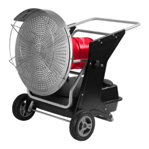
This manual suits for next models
5
Table of contents
Languages:
Other Vynckier Heater manuals