Vytran PTR-200-PRL User manual

-~
ARTISAN
®
~I
TECHNOLOGY
GROUP
Your definitive source
for
quality
pre-owned
equipment.
Artisan Technology
Group
Full-service,
independent
repair
center
with
experienced
engineers
and
technicians
on staff.
We
buy
your
excess,
underutilized,
and
idle
equipment
along
with
credit
for
buybacks
and
trade-ins
.
Custom
engineering
so
your
equipment
works
exactly as
you
specify.
•
Critical
and
expedited
services
•
Leasing
/
Rentals/
Demos
• In
stock/
Ready-to-ship
•
!TAR-certified
secure
asset
solutions
Expert
team
ITrust
guarantee
I
100%
satisfaction
All
tr
ademarks,
br
a
nd
names, a
nd
br
a
nd
s a
pp
earing here
in
are
th
e property of
th
e
ir
r
es
pecti
ve
ow
ner
s.
Visit our website - Click HERE

PTR
PTRPTR
PTR
-
--
-
200
200200
200
-
--
-
PRL
PRLPRL
PRL
Automated
Automated Automated
Automated Polyimide Recoater
Polyimide RecoaterPolyimide Recoater
Polyimide Recoater
w
ww
with
ith ith
ith Linear Proof Tester
Linear Proof TesterLinear Proof Tester
Linear Proof Tester
Operator’s Manual
Version 1.2
United States:
1400 Campus Drive West •Morganville, NJ 07751
+1 (732) 972-2880 •+1 (800) 421-8847 •Fax +1 (732) 972-6229
England:
8, Kew Court •Pynes Hill Office Campus •Exeter, EX2 5AZ
+44 (0) 1392 445777 •Fax +44 (0) 1392 445009
Web: http://www.vytran.com

PTR-200-PRL Operator’s Manual Version 1.2. Printed in the United States.
The contents of this manual are the property of Vytran LLC and are copyrighted. Under the copyright
laws, the documentation may not be copied, photocopied, reproduced, translated, or reduced to any
electronic medium or machine-readable form, in whole or part, without the prior written consent of Vytran
LLC.
Copyright 2006 Vytran LLC
1400 Campus Drive
Morganville, NJ 07751 USA
Phone: +1 (732)-972-2880
+1 (800)-421-8847
FAX: +1 (732)-972-6229
http://www.vytran.com

Vytran LLC: PTR-200-PRL Polyimide Recoater Operator’s Manual Version 1.2 iii
Table of Contents
1Introduction............................................................................................................................................ 1
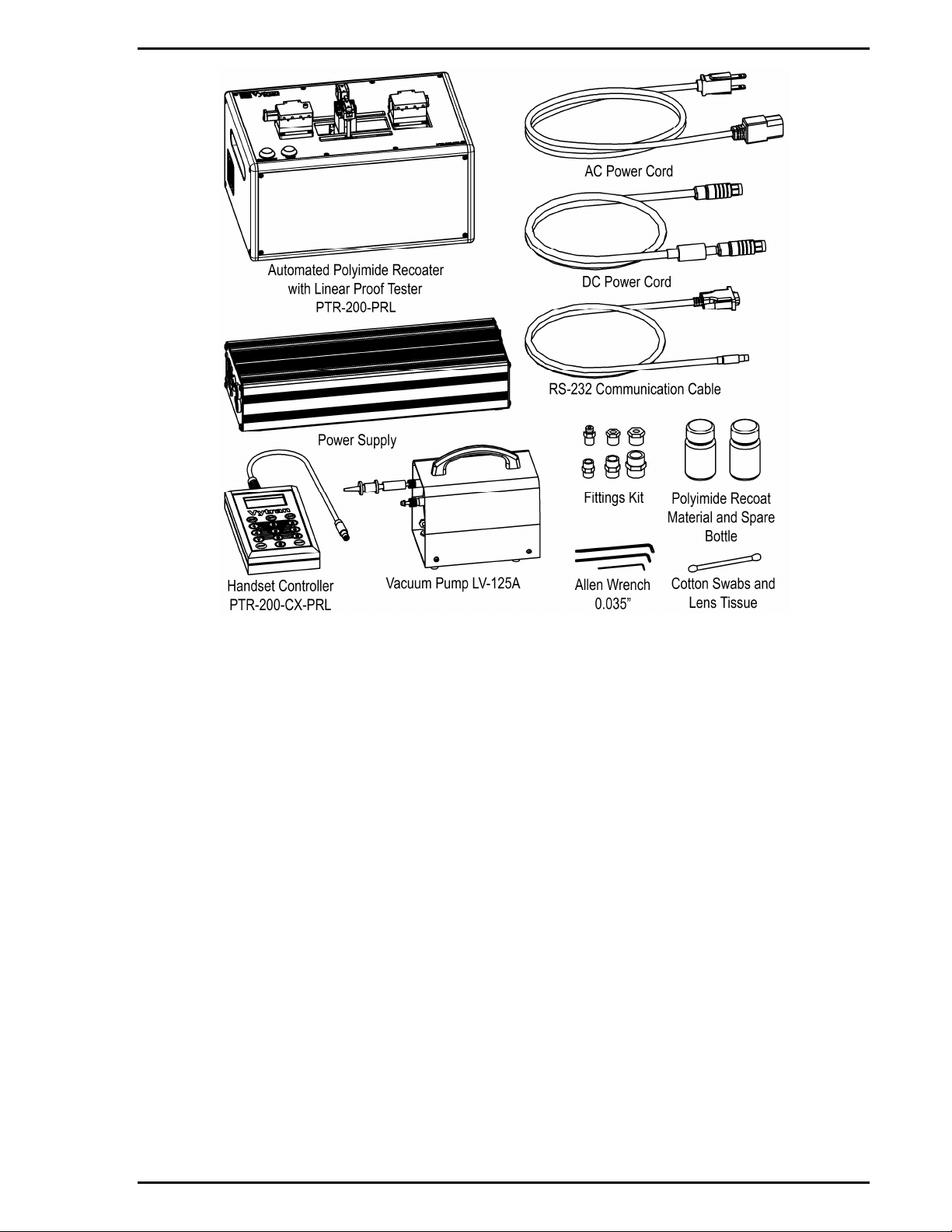
1.1 Parts Checklist............................................................................................................................... 1
1.2 Powering Up................................................................................................................................... 2
1.3 Shutting Down................................................................................................................................ 2
2Controlling the PTR-200-PRL................................................................................................................ 3
2.1 Main Menu ..................................................................................................................................... 3
2.2 Configuration Menus...................................................................................................................... 3
2.2.1 Inject........................................................................................................................................ 3
2.2.2 Undercoat ............................................................................................................................... 3
2.2.3 Overcoat ................................................................................................................................. 4
2.2.4 Recoat Length......................................................................................................................... 5
2.2.5 Proof Test ............................................................................................................................... 5
2.3 Options Menu................................................................................................................................. 6
2.4 Parameter Limits............................................................................................................................ 7
2.5 Configuration Menu Flow Chart..................................................................................................... 8
2.6 Options Menu Flowchart.............................................................................................................. 12
2.7 Abort Flowchart............................................................................................................................ 14
3Recoat Injection System...................................................................................................................... 15
3.1 Priming the Injection System ....................................................................................................... 15
3.2 Cleaning the Die........................................................................................................................... 17
4Recoat and Proof Test Process .......................................................................................................... 19
4.1 The Polyimide Recoat Process.................................................................................................... 19
4.2 The Fiber Holding Blocks, V-Grooves, and Inserts...................................................................... 19
4.3 Stripped Fiber Requirements....................................................................................................... 19
4.4 Loading......................................................................................................................................... 20
4.5 Recoating..................................................................................................................................... 21
4.6 Proof Testing................................................................................................................................ 21
4.7 Unloading..................................................................................................................................... 22
5Maintenance........................................................................................................................................ 23
5.1 Planned Maintenance .................................................................................................................. 23
5.2 Inspecting the Fiber Holding Blocks............................................................................................. 23
5.3 Inspecting and Cleaning the Die.................................................................................................. 23
5.4 Load Cell Calibration.................................................................................................................... 24
5.5 Flush Recoat System................................................................................................................... 24
5.6 Purge Recoat System.................................................................................................................. 24
5.7 Replacing Recoat Material........................................................................................................... 25
5.8 Replacing a Heater ...................................................................................................................... 25
5.9 Changing the Fiber Holding Block V-Grooves............................................................................. 25
5.10 Replacing the Die..................................................................................................................... 26
Appendix A: MSDS PI2525 ........................................................................................................................ 27
Appendix B: MSDS NMP............................................................................................................................ 35
Appendix C: Pyralin Product Information ................................................................................................... 43

Vytran LLC: PTR-200-PRL Polyimide Recoater Operator’s Manual Version 1.2 iv
Table of Figures
Figure 1: System Components.................................................................................................................... 2
Figure 2: Recoat Bottle Access.................................................................................................................. 16
Figure 3: Recoat Material Flow................................................................................................................... 16
Figure 4: Recoat and Proof Test Components........................................................................................... 20
Figure 5: Fiber Position .............................................................................................................................. 20

Introduction
Vytran LLC: PTR-200-PRL Polyimide Recoater Operator’s Manual Version 1.2 1
1 Introduction
The PRL-200 is designed for recoating and proof testing polyimide coated fibers. It operates on a coat,
cure and test recoat method, whereby a layer of polyimide is applied to the fiber through a die, followed
by a filament heater to cure the polyimide and upon completing the recoat a linear proof test. When
configured and operated properly, the PTR-200-PRL is capable of producing a high quality and a uniform
polyimide recoat.
1.1 Parts Checklist
When unpacking the PTR-200-PRL for the first time, check to make sure that you have the following
accessories:
•PTR-200-PRL Automated Polyimide Recoater with Linear Proof Tester
•12.0V Power supply (PSU)
•AC power cord
•DC power cable
•RS-232 communication cable
•Fittings kit
•Tool kit containing:
1 oz. bottle HD MicroSystems PI2525 Polyimide Recoat Material
1 oz. spare bottle
Cotton swabs
5/64” Allen key
3/32” Allen key
0.035” Allen key
•External vacuum pump with vacuum line
•PTR-200-CX-PRL Handset Controller
If you are missing any of the above or need replacements, please contact Vytran.

Introduction
Vytran LLC: PTR-200-PRL Polyimide Recoater Operator’s Manual Version 1.2 2
Figure 1: System Components
1.2 Powering Up
The PTR-200-PRL Power Supply Unit (PSU) accepts an AC input of 90-260 VAC; 47-63 Hz. Connect
both the AC power cord and the DC power cable to the external Power Supply. Connect the Handset
Controller and the DC power cable to the PTR-200-PRL.
Turn on the power supply and then turn on the PTR-200-PRL using the ON/OFF rocker switch located on
the back of the recoater. The PTR-200-PRL will run an initialization process that includes homing the
recoat die and tensioning motors and operating the recoat die (close/open). During the initialization
process, the Handset Controller will display the status of the system. Once the homing process is
completed, the Handset Controller displays the Main Menu screen and the PTR-200-PRL is ready for
recoating.
1.3 Shutting Down
To shut down the PTR-200-PRL:
1. Turn off the PTR-200-PRL using the on/off rocker switch located on the back of the recoater.
2. Turn off the power supply.

Controlling the PTR-200-PRL
Vytran LLC: PTR-200-PRL Polyimide Recoater Operator’s Manual Version 1.2 3
2 Controlling the PTR-200-PRL
The PTR-200-PRL is configured and controlled from Vytran’s PRL-200-CX-PRL Handset Controller,
which also provides feedback and status of the unit. If the operator does not need to change parameter
settings or receive status prompts, the Handset Controller can be removed and the unit operated simply
by pressing the blue RECOAT and TEST buttons.
The Handset Controller allows the user to interface with the unit and modify the settings. The Handset
Controller is based on a three (3) menus:
•Main Menu
•Configuration Menu
•Options Menu
Each menu and its contents are described below.
2.1 Main Menu
The Main Menu displays the unit status. From this menu, press the “CFG” button to enter the
Configuration Menu or press the “OPT” button to enter the Options Menu.
2.2 Configuration Menus
There are three (3) levels to the Configuration Menu. At level one the user can select from five (5)
topics - Inject, Undercoat, Overcoat, Recoat Length, or Proof Test. Within each of these topics are the
parameters which can be viewed and/or copied. Below is a description of the five (5) topics and each
topics parameters.
2.2.1 Inject
Inject Rate (µl/sec): This parameter is the polyimide injection rate, in microliters per
second, into the die. The optimum Inject Rate will be dependant on
the polyimide material being used.
Undercoat Qty. (µl): This parameter is the quantity of polyimide material, in microliters,
injected into the die for the first loop of the head (the undercoat).
The optimum Undercoat Qty will be primarily dependant on the bare
fiber diameter, die size, and the length of the recoat.
Overcoat Qty. (µl): This parameter is the quantity of polyimide material injected into the
die, in microliters, after the first loop of the head. The optimum
Overcoat Qty will be primarily dependant on the die size, and the
length of the recoat.
2.2.2 Undercoat
Head Sweep Vel. (steps/sec): This parameter is the velocity of the head, in steps/sec, for the first
loop of depositing polyimide. The optimum Head Sweep Velocity
will be dependant on the bare fiber diameter, die size, and material
being deposited.
Left Precure Temp
(degrees centigrade): This parameter is the approximate temperature, in degrees
centigrade, applied to the left heater during a polyimide deposition.
The optimum Left Precure Temp will be dependant on the Head
Sweep Velocity, and material being deposited. The temperature is
calibrated at the center of the heater while stationary. The Left
Precure Temp is designed to evaporate the volatiles of the polyimide
being deposited.

Controlling the PTR-200-PRL
Vytran LLC: PTR-200-PRL Polyimide Recoater Operator’s Manual Version 1.2 4
Left Cure Temp
(degrees centigrade): This parameter is the approximate temperature, in degrees
centigrade, applied to the left heater during imidization (the pass
after deposition). The optimum Left Cure Temp will be dependant
on the Head Sweep Velocity and the polyimide material. The
temperature is calibrated at the center of the heater while stationary.
The Left Cure Temp is designed to imidize the polyimide after the
volatiles have been evaporated.
Right Precure Temp
(degrees centigrade): This parameter is the approximate temperature, in degrees
centigrade, applied to the right heater during a polyimide deposition.
The optimum Right Precure Temp will be dependant on the Head
Sweep Velocity, and material being deposited. The temperature is
calibrated at the center of the heater while stationary. The Right
Precure Temp is designed to evaporate the volatiles of the polyimide
being deposited.
Right Cure Temp
(degrees centigrade): This parameter is the approximate temperature, in degrees
centigrade, applied to the right heater during imidization (the pass
after deposition). The optimum Right Cure Temp will be dependant
on the Head Sweep Velocity and the polyimide material. The
temperature is calibrated at the center of the heater while stationary.
The Right Cure Temp is designed to imidize the polyimide after the
volatiles have been evaporated.
2.2.3 Overcoat
Number of Overcoats: This parameter is the number of loops the head will make. The
optimum Number of Overcoats will be dependant on the polyimide
thickness layer desired (which will be dependant on the undercoat
layer thickness and the parameter settings for the overcoat(s)).
Head Sweep Vel (steps/sec): This parameter is the velocity of the head, in steps/sec, for the first
loop of depositing polyimide. The optimum Head Sweep Velocity
will be dependant on the die size, and material being deposited.
Left Precure Temp
(degrees centigrade): This parameter is the approximate temperature, in degrees
centigrade, applied to the left heater during a polyimide deposition.
The optimum Left Precure Temp will be dependant on the Head
Sweep Velocity, and material being deposited. The temperature is
calibrated at the center of the heater while stationary. The Left
Precure Temp is designed to evaporate the volatiles of the polyimide
being deposited.
Left Cure Temp
(degrees centigrade): This parameter is the approximate temperature, in degrees
centigrade, applied to the left heater during imidization (the pass
after deposition). The optimum Left Cure Temp will be dependant
on the Head Sweep Velocity and the polyimide material. The
temperature is calibrated at the center of the heater while stationary.
The Left Cure Temp is designed to imidize the polyimide after the
volatiles have been evaporated.
Right Precure Temp
(degrees centigrade): This parameter is the approximate temperature, in degrees
centigrade, applied to the right heater during a polyimide deposition.
The optimum Right Precure Temp will be dependant on the Head
Sweep Velocity, and material being deposited. The temperature is
calibrated at the center of the heater while stationary. The Right
Precure Temp is designed to evaporate the volatiles of the polyimide
being deposited.

Controlling the PTR-200-PRL
Vytran LLC: PTR-200-PRL Polyimide Recoater Operator’s Manual Version 1.2 5
Right Cure Temp
(degrees centigrade): This parameter is the approximate temperature, in degrees
centigrade, applied to the right heater during imidization (the pass
after deposition). The optimum Right Cure Temp will be dependant
on the Head Sweep Velocity and the polyimide material. The
temperature is calibrated at the center of the heater while stationary.
The Right Cure Temp is designed to imidize the polyimide after the
volatiles have been evaporated.
Overlap Delta (mm): This parameter is the additional distance, in millimeters, the head
will travel on each pass. This will effectively taper the transition from
original polyimide to recoated polyimide.
2.2.4 Recoat Length
Recoat Length (mm): This parameter is the desired bare fiber length, in millimeters, to be
recoated. The actual recoat length will be approximately 8
millimeters longer on each end in order to compensate for the width
of the head and the fiber load position.
2.2.5 Proof Test
Proof Test Units: This menu allows the user to select the desired units for displaying
the Proof Test Level. Unit selections are: Newtons, kpsi, and grams.
Proof Test Level (units): This parameter is the Proof Test Level, in units user selected, to be
applied after the recoat has been completed.
Proof Test Rate (mm/sec) This parameter is the rate, in millimeters per second, at which the
Proof Test Level will be applied. The optimum rate is that which
achieves the desired proof test level within 3 - 5 seconds of load
applying time.

Controlling the PTR-200-PRL
Vytran LLC: PTR-200-PRL Polyimide Recoater Operator’s Manual Version 1.2 6
2.3 Options Menu
From the Options Menu, various system level configuration parameters and functions can be edited or
executed.
Recoat Tension (Newtons): This parameter is the tension, in Newtons, applied to the fiber prior
to initiating a recoat. The PTR-200-PRL also monitors the tension
during the recoat and will automatically abort if the tension varies
significantly from the Recoat Tension. The auto abort is intended to
protect both the die and fiber.
Heater Settle Time (msec): This parameter is the amount of time, in milliseconds, allowed for the
heater to stabilize when changing temperatures.
Die Close Time (msec): This parameter is the amount of time, in milliseconds, allowed for the
die to close prior to execution of the subsequent process.
Fiber Unload Time (msec): This parameter is the amount of time, in milliseconds, allowed for the
operator to unload the fiber prior to the PTR-200-PRL performing a
system reset.
Inject to Die Qty (µL) This option is the quantity of polyimide material, in microliters, which
will be injected into the die upon entering the quantity. This option is
intended for use when changing materials or purging the system
prior to storage.
Head to Home: This option performs a homing of the head and is useful as a
diagnostic tool.
Tension Home: This option performs a homing of the proof test load cell and is
useful as a diagnostic tool.
Move Head to Start: This option performs a movement of the head to the start position.
The start position is calculated based upon the recoat length,
overlap delta, and the number of overcoats. Use of the Head to
Start and Head to Stop options enables the user to verify the correct
recoat length has been entered.
Move Head to Stop: This option performs a movement of the head to the stop position.
The stop position is calculated based upon the recoat length,
overlap delta, and the number of overcoats. Use of the Head to
Start and Head to Stop options enables the user to verify the correct
recoat length has been entered.
Recoat Request State: This option enables or disables the request to input a recoat length
each time the process is run. This option is primarily used when the
length to be recoated varies significantly from recoat to recoat.
Set/Run Purge Cycles: This option is the number of recoat pump purge cycles that will be
run upon entering the quantity.
Recoat Tension This option is the amount of tension that will be applied to the fiber
prior to the recoating.

Controlling the PTR-200-PRL
Vytran LLC: PTR-200-PRL Polyimide Recoater Operator’s Manual Version 1.2 7
2.4 Parameter Limits
Parameter Min Max
Inject Rate (µL/sec) 0.01 2.00
Undercoat Qty (µL) 0.01 10.00
Overcoat Qty (µL) 0.01 10.00
Undercoat Head Sweep Vel (mm/sec) 0.01 20.00
Undercoat Left Precure Temp (°C) 100 200
Undercoat Left Cure Temp (°C) 100 300
Undercoat Right Precure Temp (°C) 100 200
Undercoat Right Cure Temp (°C) 100 300
Number of Overcoats 1 10
Overcoat Head Sweep Vel (mm/sec) 0.01 20.00
Overcoat Left Precure Temp (°C) 100 200
Overcoat Left Cure Temp (°C) 100 300
Overcoat Right Precure Temp (°C) 100 200
Overcoat Right Cure Temp (°C) 100 300
Overlap Delta (mm) 100 200
Recoat Length (mm) 0 2
Proof Test Level (Newtons) 0 20
Proof Test Rate (mm/sec) 0.1 5.0
Recoat Tension (Newtons) 2 10
Heater Stabilize Time (msec) 1 10000
Die Close Time (msec) 250 2500
Fiber Unload Time (msec) 5000 30000
Heater Stabilize Time (msec) 1 10000
Inject to Die Qty (µL) 1 100

Controlling the PTR-200-PRL
Vytran LLC: PTR-200-PRL Polyimide Recoater Operator’s Manual Version 1.2 8
2.5 Configuration Menu Flow Chart
This flowchart is a guide for navigating through the Configuration Menu, and shows the display prompts
and button key presses for viewing and editing the Configuration Parameters.
PRL-200-Cx
Params = CFG
Option =OPT
CFG
Scroll=1 Escape=ESC
SELECT SUB-MENU
Inject
SELECT
Scroll=1 Escape=ESC
INJECT PARAMETERS
Inject Rate
1
SELECT
Save=CFG Escape=ESC
INJECT RATE
Old = 0.35 ul/s
New = 0.40 ul/s
CFG
SET INJECT RATE
New = 0.040 ul/s
Writing to PRL-200
please wait...
Scroll=1 Escape=ESC
INJECT PARAMETERS
Undercoat Quantity
Save=CFG Escape=ESC
UNDERCOAT QUANTITY
Old = 01.06 ul
New = 01.25 ul
CFG
UNDERCOAT QUANTITY
New = 01.25 ul
Writing to PRL-200
please wait...
Scroll=1 Escape=ESC
INJECT PARAMETERS
Overcoat Quantity
Save=CFG Escape=ESC
OVERCOAT QUANTITY
Old = 00.35 ul
New = 00.21 ul
CFG
OVERCOAT QUANTITY
New = 00.21 ul
Writing to PRL-200
please wait...
1
ESC
1
1ESC
ESC
ESC
ESC
ESC
ESC

Controlling the PTR-200-PRL
Vytran LLC: PTR-200-PRL Polyimide Recoater Operator’s Manual Version 1.2 9
Scroll=1 Escape=ESC
SELECT SUB-MENU
Undercoat
SELECT
Scroll=1 Escape=ESC
UNDERCOAT PARAMETERS
Head Sweep Velocity
1
SELECT
Save=CFG Escape=ESC
UNDERCOAT HEAD VEL
Old = 00.4 mm/s
New = 00.3 mm/s
CFG UNDERCOAT HEAD VEL
New = 00.3 mm/s
Writing to PRL-200
please wait...
Scroll=1 Escape=ESC
UNDERCOAT PARAMETERS
Left Precure Temp
1
SELECT
Save=CFG Escape=ESC
UNDERCOAT L-PRECURE
Old = 150 °C
New = 155 °C
CFG
UNDERCOAT L-PRECURE
New = 155 °C
Writing to PRL-200
please wait...
Scroll=1 Escape=ESC
UNDERCOAT PARAMETERS
Left Cure Temp
1
SELECT
Save=CFG Escape=ESC
UNDERCOAT LEFT CURE
Old = 190 °C
New = 195 °C
CFG
UNDERCOAT LEFT CURE
New = 195 °C
Writing to PRL-200
please wait...
Scroll=1 Escape=ESC
UNDERCOAT PARAMETERS
Right Precure Temp
1
SELECT
Save=CFG Escape=ESC
UNDERCOAT R-PRECURE
Old = 150 °C
New = 155 °C
CFG
UNDERCOAT R-PRECURE
New = 155 °C
Writing to PRL-200
please wait...
Scroll=1 Escape=ESC
UNDERCOAT PARAMETERS
Right Cure Temp
1
SELECT
Save=CFG Escape=ESC
UNDERCOAT RIGHT CURE
Old = 190 °C
New = 195 °C
CFG
UNDERCOAT RIGHT CURE
New = 195 °C
Writing to PRL-200
please wait...
1
ESC
ESC
ESCESC
ESCESC
ESCESC
ESCESC
ESC

Controlling the PTR-200-PRL
Vytran LLC: PTR-200-PRL Polyimide Recoater Operator’s Manual Version 1.2 10
Scroll=1 Escape=ESC
SELECT SUB-MENU
Overcoat
SELECT
Scroll=1 Escape=ESC
OVERCOAT PARAMETERS
Head Sweep Velocity
1
SELECT
Save=CFG Escape=ESC
OVERCOAT HEAD VEL
Old = 01.0 mm/s
New = 01.3 mm/s
CFG
OVERCOAT HEAD VEL
New = 01.3 mm/s
Writing to PRL-200
please wait...
Scroll=1 Escape=ESC
OVERCOAT PARAMETERS
Left Precure Temp
1
SELECT
Save=CFG Escape=ESC
OVERCOAT L-PRECURE
Old = 150 °C
New = 155 °C
CFG
OVERCOAT L-PRECURE
New = 155 °C
Writing to PRL-200
please wait...
Scroll=1 Escape=ESC
OVERCOAT PARAMETERS
Left Cure Temp
1
SELECT
Save=CFG Escape=ESC
OVERCOAT LEFT CURE
Old = 190 °C
New = 195 °C
CFG
OVERCOAT LEFT CURE
New = 195 °C
Writing to PRL-200
please wait...
Scroll=1 Escape=ESC
OVERCOAT PARAMETERS
Right Precure Temp
1
SELECT
Save=CFG Escape=ESC
OVERCOAT R-PRECURE
Old = 150 °C
New = 155 °C
CFG
OVERCOAT R-PRECURE
New = 155 °C
Writing to PRL-200
please wait...
Scroll=1 Escape=ESC
OVERCOAT PARAMETERS
Right Cure Temp
1
SELECT
Save=CFG Escape=ESC
OVERCOAT RIGHT CURE
Old = 190 °C
New = 195 °C
CFG
OVERCOAT RIGHT CURE
New = 195 °C
Writing to PRL-200
please wait...
Scroll=1 Escape=ESC
OVERCOAT PARAMETERS
Number of Overcoats
1
SELECT
Save=CFG Escape=ESC
SET NO. OF OVERCOATS
Old = 04
New = 05
CFG
SET NO. OF OVERCOATS
New = 05
Writing to PRL-200
please wait...
Scroll=1 Escape=ESC
OVERCOAT PARAMETERS
Overlap Delta
SELECT
Save=CFG Escape=ESC
SET OVERLAP DELTA
Old = 1.0 mm
New = 1.2 mm
CFG
SET OVERLAP DELTA
New = 1.2 mm
Writing to PRL-200
please wait...
1
ESC
ESC
ESCESC
ESC ESC
ESC
ESC
ESC
ESC
ESC
ESC
ESC
ESC
1
ESC

Controlling the PTR-200-PRL
Vytran LLC: PTR-200-PRL Polyimide Recoater Operator’s Manual Version 1.2 11
Scroll=1 Escape=ESC
SELECT SUB-MENU
Recoat Length
Scroll=1 Escape=ESC
SELECT SUB-MENU
Proof Test
SELECT
Save=CFG Escape=ESC
RECOAT LENGTH
Old = 10 mm
New = 12 mm
CFG
RECOAT LENGTH
New = 12 mm
Writing to PRL-200
please wait...
SELECT
Scroll=1 Escape=ESC
PROOF TEST PARAMETERS
Proof Test Level
1
SELECT
Save=CFG Escape=ESC
PROOF TEST LEVEL
Old = 109 kpsi
New = 125 kpsi
CFG
PROOF TEST LEVEL
New = 125 kpsi
Writing to PRL-200
please wait...
Scroll=1 Escape=ESC
PROOF TEST PARAMETERS
Proof Test Step Rate
1
SELECT
Save=CFG Escape=ESC
PROOF TEST RATE
Old = 2.0 mm/s
New = 1.8 mm/s
CFG
PROOF TEST RATE
New = 1.8 mm/s
Writing to PRL-200
please wait...
Scroll=1 Escape=ESC
PROOF TEST PARAMETERS
Proof Test Units
1
SELECT
Scroll=1 Escape=ESC
PROOF TEST UNITS
kpsi
PROOF TEST UNITS
kpsi
Writing to PRL-200
please wait...
SELECT
1
Scroll=1 Escape=ESC
PROOF TEST UNITS
N
PROOF TEST UNITS
N
Writing to PRL-200
please wait...
SELECT
1
Scroll=1 Escape=ESC
PROOF TEST UNITS
g
PROOF TEST UNITS
g
Writing to PRL-200
please wait...
SELECT
1
ESC
ESC
1
ESC
ESC

Controlling the PTR-200-PRL
Vytran LLC: PTR-200-PRL Polyimide Recoater Operator’s Manual Version 1.2 12
2.6 Options Menu Flowchart
This flowchart is a guide for navigating through the Options Menu, and shows the display prompts and
button key presses for editing parameters and executing system related functions.
PRL-200-Cx
Params = CFG
Option =OPT
OPT
Scroll=1 Escape=ESC
SELECT SUB-MENU
Recoat Tension
SELECT
Save=CFG Escape=ESC
RECOAT TENSION
Old = 053
New = 059
CFG RECOAT TENSION
New = 059
Writing to PRL-200
please wait...
ESC
1
Scroll=1 Escape=ESC
SELECT SUB-MENU
Heater Settle Time
SELECT
Save=CFG Escape=ESC
HEATER SETTLE TIME
Old = 03.00 s
New = 04.00 s ESC
HEATER SETTLE TIME
New = 04.00 s
Writing to PRL-200
please wait...
CFG
1
Scroll=1 Escape=ESC
SELECT SUB-MENU
Inject ot Die Qty
SELECT
Save=CFG Escape=ESC
INJECT TO DIE QTY
Old = 100 µl
New = 110 µl ESC
INJECT TO DIE QTY
New = 110 µl
Writing to PRL-200
please wait...
CFG
1
Scroll=1 Escape=ESC
SELECT SUB-MENU
Fiber Unload Time
SELECT
Save=CFG Escape=ESC
FIBER UNLOAD TIME
Old = 10 s
New = 15 s ESC
FIBER UNLOAD TIME
New = 15 s
Writing to PRL-200
please wait...
CFG
1
Scroll=1 Escape=ESC
SELECT SUB-MENU
Die Close Time
SELECT
Save=CFG Escape=ESC
DIE CLOSE TIME
Old = 1500 ms
New = 2000 ms ESC
DIE CLOSE TIME
New = 2000 ms
Writing to PRL-200
please wait...
CFG
ESC
ESC
ESC
ESC
ESC
1

Controlling the PTR-200-PRL
Vytran LLC: PTR-200-PRL Polyimide Recoater Operator’s Manual Version 1.2 13
Scroll=1 Escape=ESC
SELECT SUB-MENU
Head to Home SELECT Re-Homing Die Head
please wait...
1
Scroll=1 Escape=ESC
SELECT SUB-MENU
Tension Home SELECT Re-Homing Proof Test
please wait...
1
Scroll=1 Escape=ESC
SELECT SUB-MENU
Move Head to Start SELECT Moving Head to Start
please wait...
1
Scroll=1 Escape=ESC
SELECT SUB-MENU
Move Head to Stop SELECT Moving Head to Stop
please wait...
1
Scroll=1 Escape=ESC
SELECT SUB-MENU
Recoat Request State SELECT Scroll=1 Escape=ESC
RECOAT REQUEST STATE
Enabled
ESC
Scroll=1 Escape=ESC
RECOAT REQUEST STATE
Disabled
ESC
1
Scroll=1 Escape=ESC
SELECT SUB-MENU
Set/Run Purge Cycles SELECT Save=CFG Escape=ESC
SET/RUN PURGE CYCLES
Old = 5
New = 7
ESC
SET/RUN PURGE CYCLES
New = 7
Writing to PRL-200
please wait...
CFG
1
Scroll=1 Escape=ESC
SELECT SUB-MENU
Recoat Tension SELECT Save=CFG Escape=ESC
RECOAT TENSION
Old = 053
New = 058
ESC
RECOAT TENSION
New = 058
Writing to PRL-200
please wait...
CFG
ESC
ESC
ESC
ESC
ESC
ESC
ESC

Controlling the PTR-200-PRL
Vytran LLC: PTR-200-PRL Polyimide Recoater Operator’s Manual Version 1.2 14
2.7 Abort Flowchart
Even after the recoat process has been initiated it is possible to abort the process if required. The Abort
Flowchart shows the display prompts and button key presses to abort a recoat process.
PRL-200-Cx
Recoating...
ESC
Yes=SELECT No=ESC
!! PLEASE CONFIRM !!
Abort Macro?
SELECT
ESC
ESC
ABORTING
please wait...
ABORT COMPLETE
Remove Fibre, then
Press ESC to Reset
System Resetting....
please wait...
PRL-200-Cx
SYSTEM READY
PRL-200--Cx
Params = CFG
Option = OPT
5s

Recoat Injection System
Vytran LLC: PTR-200-PRL Polyimide Recoater Operator’s Manual Version 1.2 15
3 Recoat Injection System
The PTR-200-PRL has an automatic recoat injection pump fitted inside the unit. The pump is based on
an automated syringe and distribution valve that can select one of three ports (Fill, Purge, or Inject)
through which it can either draw or inject recoat material (see Figure 3). A bottle containing recoat
material is installed directly on the pump, with the pump “Fill” tube inserted into the bottom of the bottle. A
“Purge” tube runs from the pump to the top of the recoat bottle, and is used for cycling material back into
the bottle. An “Inject” tube runs from the pump to the inject port of the die, which is located in the center
of the lower right die. Once all air is purged from the injection system, the pump provides very accurate
control of the volume and velocity of recoat material injection.
The recommended recoat material for use in the PTR-200-PRL is Pyralin PI2525, which is manufactured
by HD MicroSystems. This is a fast imidizing at lower temperature coating. Do not attempt to use
alternate recoat materials without first consulting Vytran on compatibility with the PRL.
Note: Pyralin PI2525 recoat material does have a limited shelf life of approximately 24 months from date
of manufacture when stored at 0 to 18 degrees Centigrade. PI2525 is stable at room temperature (21
degrees Centigrade) for approximately 4 weeks with no significant change in properties. Using material
that has passed its expiration date may cause both pump performance and recoat quality issues.
3.1 Priming the Injection System
It is very important to remove all air from the recoat injection system prior to performing a recoat. When
operating the system for the first time, the pump must be filled with recoat material and cleared of all air in
the pump and tubing. In order to clear the inject tube, recoat material must be injected out through the
mold inject port and collected and disposed of. Make sure to have cotton swabs and NMP (1-Methyl-2-
pyrrolidinone) available for this purpose prior to starting this procedure. NMP is the recommended
solvent for cleaning uncured polyimide recoat material.
WARNING: Polyimide recoat materials can be hazardous to your health if not handled properly. Read
the Material Safety Data Sheet provided in Appendix X, and make sure to follow all precautionary
guidelines when working with this material.
To prime the recoat injection system:
1. Turn off power to the PTR-200-PRL.
2. Remove the front plate of the PTR-200-PRL by using the 3/32 Allen wrench provided in the tool
kit to remove the four (4) black socket-head cap screws located at the corners of the plate.
3. The recoat pump is located on the left side of the PTR-200-PRL as shown in Figure 2. Unscrew
the brown recoat bottle located at the front of the pump and remove by angling out through the
front opening. The red Fill tube will flex to allow removal.
4. For new systems, replace the empty recoat bottle shipped with the unit with a new bottle of recoat
material. For systems that have previously been run with recoat material, the recoat injection
system should be flushed clean prior to adding new material (see 5.5).
5. Screw the new recoat bottle into place and replace the front panel and the four (4) socket head
cap screws.
Table of contents