Deutsch
1
Broome 10 Installationsanleitung
Stand 02.2022
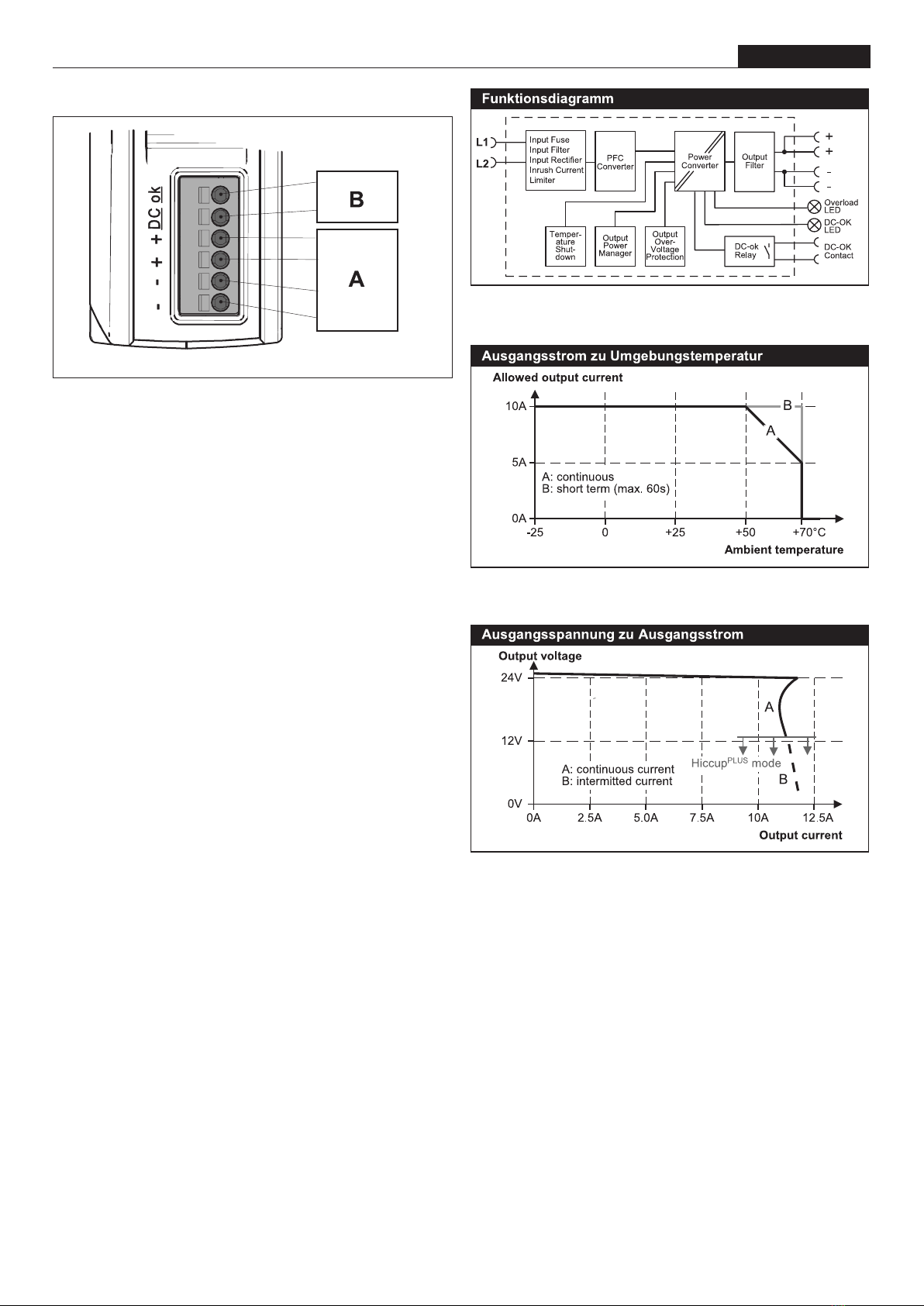
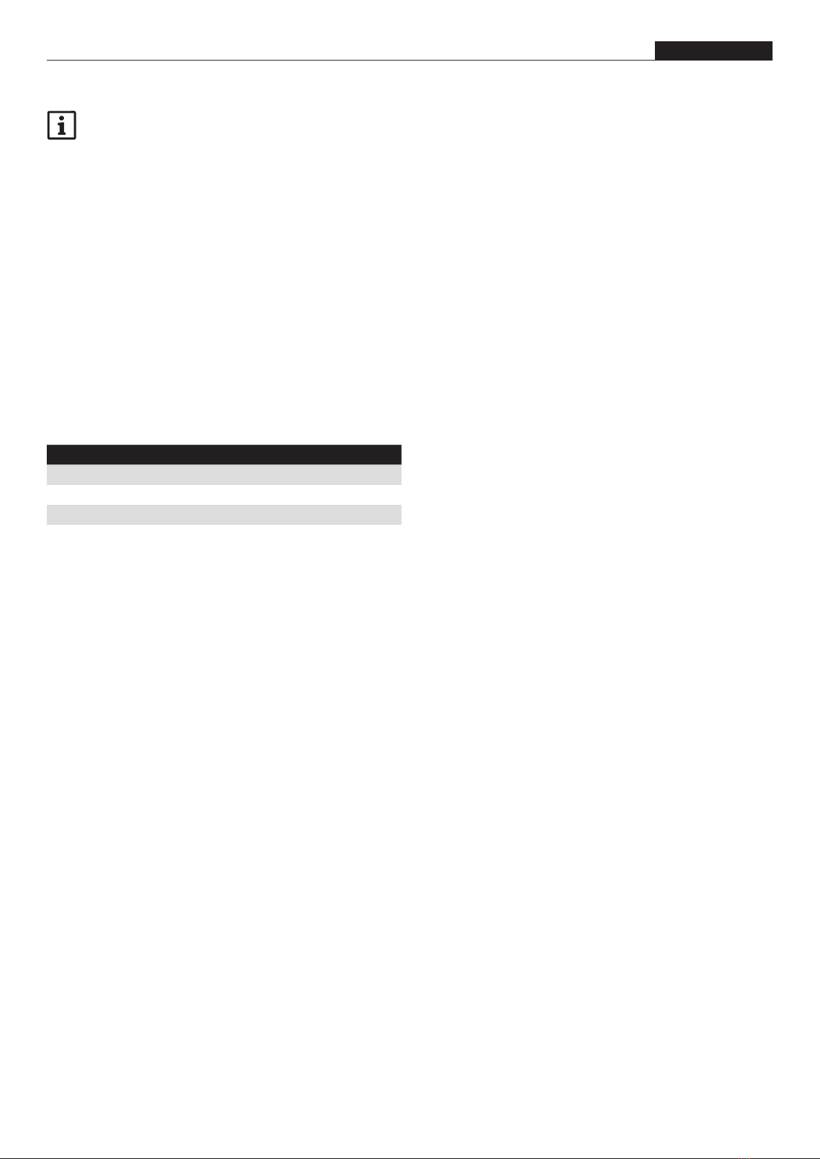
24Vdc/10A Netzteil
Weitere Informationen nden Sie in der zugehöri gen Doku-
mentation des jeweiligen Artikels
unter www.woehner.de
Kurzbeschreibung
Das Netzteil Broome10 ist ein Industrienetzteil für 3-phasige
Netz-
systeme, das für den Einsatz mit dem modularen Energiever-
teilungssystem Crossboard® entwickelt wurde. Es liefert eine
potentialfreie, stabilisierte und galvanisch getrennte SELV / PELV-
Ausgangsspannung.
Verwendungszweck
Dieses Gerät ist für den Einbau in eine Anlage ausgelegt und für
den Gebrauch in beispielsweise industriellen Steuerungs-, Ener-
gieverteilungs- sowie Instrumentierungsausrüstungen bestimmt.
Verwenden Sie dieses Gerät nicht in Anlagen, in denen eine Fehl-
funktion schwere Verletzungen verursachen oder das Leben von
Menschen gefährden könnte.
1. Inhalt der EU-Konformitätserklärung
Hersteller: Wöhner GmbH & Co. KG,
Mönchrödener Str.10, 96472 Rödental, Germany
Produktbezeichnung Artikelnummer
BROOME10®CrossBoard Netzteil 10 A 36200
BROOME10®30Compact Netzteil 10 A 36201
BROOME10®60Classic Netzteil 10 A 36202
Das vorstehend bezeichnete Produkt stimmt mit den wesentli-
chen Anforderungen der nachfolgenden Richtlinie(n) und deren
Änderungsrichtlinien überein:
2014/35/EU Niederspannungsrichtlinie
2014/30/EU EMV-Richtlinie
EN 61204-3:2000 Produktnorm
EN 61000-6-4:2007 + A1:2011 Produktnorm
EN 61000-6-2:2005 / AC:2005 Produktnorm
EN 61010-2-201:2013 + AC:2013 Produktnorm
2. Sicherheitshinweise/Errichtungshinweise
2.1. Allgemeine Sicherheitshinweise
• Bewahren Sie die Produktdokumentation auf
• Reparieren Sie das Gerät nicht selbst, sondern ersetzen Sie
es durch ein gleichwertiges Gerät. Reparaturen dürfen nur vom
Hersteller vorgenommen werden. Der Hersteller haftet nicht für
Schäden aus Zuwiderhandlung.
• Beachten Sie bei allen Arbeiten am Gerät die nationalen Si-
cherheits- und Unfallverhütungsvorschriften.
• Werden die Sicherheitsvorschriften nicht beachtet, können Tod,
schwere Körperverletzung oder hoher Sachschaden die Folge
sein.
• Dieses Gerät enthält keine zu wartenden Teile. Das Auslösen
der internen Sicherung wird durch einen internen Defekt verur-
sacht. Wenn während der Installation oder des Betriebs Schä-
den oder Fehlfunktionen auftreten sollten, schalten Sie das Ge-
rät sofort aus und senden Sie es zur Überprüfung zurück.
• Schalten Sie das Gerät vor Beginn der Arbeiten spannungsfrei.
• Das Gerät ist für den Einsatz in Bereichen mit Verschmut-
zungsgrad 2 und für den Einsatz in geschützten Umgebungen
vorgesehen.
• Das Gehäuse des Geräts besitzt eine Schutzart von IP30 ge-
mäß IEC 60529.
• Das Gerät ist für die Versorgung aus TN-, TT- und IT-Netzen
geeignet (geerdete Stern- oder ungeerdete Dreiecksnetze).
• Das Gerät ist für Überspannungskategorie III nach IEC 62477-1
ausgelegt.
• Das Gerät ist als Gerät der Schutzklasse II nach IEC 61140
ausgeführt. Ein PE-Anschluss (Schutzerde) ist nicht erforder-
lich.
2.2. Sicherheitshinweise zum Einbau / Ausbau
• Schließen Sie das Gerät nicht an oder trennen Sie es nicht,
solange die Eingangsspannung anliegt.
• Installieren Sie das Gerät in einem Gehäuse, das Schutz vor
elektrischen, mechanischen und Brandgefahren bietet.
• Stellen Sie sicher, dass die Verkabelung korrekt ist, indem Sie
alle lokalen und nationalen Vorschriften befolgen. Verwenden
Sie geeignete Kupferkabel, die für eine Betriebstemperatur von
mindestens 60° C für Umgebungstemperaturen bis + 45° C,
75° C für Umgebungstemperaturen bis + 60° C und 90° C für
Umgebungstemperaturen bis + 70° C ausgelegt sind. Stellen
Sie sicher, dass alle Litzen einer Leitung in der Klemme sind.
• Die maximale Umgebungslufttemperatur beträgt + 70° C / + 158° F.
Die Betriebstemperatur entspricht der Umgebungs- oder umge-
benden Lufttemperatur und ist deniert als die Lufttemperatur
2 cm unter dem Gerät.
• Das Gerät ist für den Betrieb in Bereichen zwischen 5 % und
95 % relativer Luftfeuchtigkeit ausgelegt. Nicht unter Spannung
setzen, wenn Betauung vorhanden ist!
• Das Gerät ist für alle Stromwerte der Zweigstromkreise ausge-
legt, getestet und zugelassen, die für das modulare Energiever-
teilsystem Crossboard® CB225 und Crossboard® CB405 zuläs-
sig sind. Ein zusätzliches Schutzgerät ist nicht erforderlich.
• Das Gerät ist für Konvektionskühlung ausgelegt und benötigt
keinen externen Lüfter. Luftstrom nicht behindern und Lüftungs-
gitter nicht abdecken!
• Halten Sie die folgenden minimalen Installationsfreiräume ein,
wenn das Gerät dauerhaft mit mehr als 50 % des Nennstroms
belastet ist: 40 mm oben, 20 mm unten, 0 mm links und rechts.
• Legen Sie keine Rückspannungen von der Last zum Ausgang
höher als 35 V an.
• Das Gerät ist für Höhen bis zu 2000 m ausgelegt.
• Nur eine Elektrofachkraft darf das Gerät in Betrieb nehmen,
montieren, ändern oder nachrüsten.
2.3. Sicherheitshinweise zum Betrieb
• Der Ausgang ist elektronisch bei Leerlauf, Überlast und Kurz-
schluss geschützt und kann beliebige Lasten, einschließlich
unbegrenzter induktiver Lasten und kapazitiver Lasten bis 1 F,
versorgen.
• Während des Betriebs stehen Teile der elektrischen Schaltge-
räte unter gefährlicher Spannung.
• Entfernen Sie während des Betriebs keine Schutzabdeckungen
von elektrischen Schaltgeräten.
• Setzen Sie das Gerät keiner mechanischen und/oder thermi-
schen Beanspruchung aus, die die beschriebene Grenze über-
schreitet.
Anwendungsbereich
Dies ist ein Produkt für Umgebung A (Industrie). In Umgebung
B (Haushalt) kann dieses Gerät unerwünschte Funkstörungen
verursachen. In diesem Fall kann der Anwender verpichtet sein,
angemessene Maßnahmen durchzuführen.