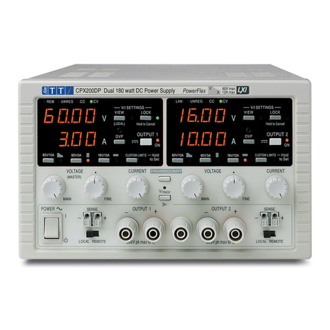
TTI CPX200 User manual

CPX200
Dual 35V 10A Power Flex Power Supply
INSTRUCTIONMANUAL

1
Table of Contents
Specification 2
Safety 4
EMC 6
Installation 7
Connections 8
Operation 9
Maintenance 11
Instructions en Francais
Sécurité 12
Installation 13
Connexions 14
Opération 15
Maintenance 17
Bedienungsanleitung auf Deutsch
Sicherheit 18
Installation 19
Anschlüsse 20
Betrieb 21
Wartung 24
Istruzioni in Italiano
Sicurezza 25
Installazione 26
Collegamento 27
Funzionamento 28
Manutenzione 30
Instrucciones en Español
Seguridad 31
Instalación 32
Conexiones 33
Funcionamiento 34
Mantenimiento 36

2
Specification
OUTPUT SPECIFICATIONS
Voltage Range:
0V to 35V
Current Range:
0A to 10A
Power Range:
Up to 175W
Output Voltage Setting:
By coarse and fine controls.
Output Current Setting:
By single logarithmic control.
Operating Mode: Constant voltage or constant current with automatic cross-over
provided that the power demanded stays within the power
envelope, see graph. Outside of this envelope the output becomes
unregulated.
Output Switch:
Electronic. Preset voltage and current displayed when off.
Output Terminals:
Universal 4mm safety binding posts on 19mm (0·75”) pitch.
Sensing: Switchable between local and remote. Spring-loaded push terminals for
remote connection.
Output Protection: Forward protection by Over-Voltage Protection (OVP) trip; maximum
voltage that should be applied to the terminals is 50V.
Reverse protection by diode clamp for reverse currents up to 3A.
OVP Range: 10% to 110% of maximum output voltage set by front panel screwdriver
adjustment.
Line Regulation:
<0.01% of maximum output for a 10% line change.
Load Regulation:
<0.05% of maximum output for a 90% load change, using remote sense.
Ripple & Noise
(20MHz bandwidth):
5mVrms max; typically <2mVrms, <20mV pk-pk, both outputs fully
loaded (7A @ 25V), constant voltage mode.
Transient Load Response:
<2ms to within 100mV of set level for a 5% to 95% load change.
Temperature Coefficient:
Typically <100ppm/°C
Status Indication: Output on lamp.
Constant voltage mode lamp.
Constant current mode lamp.
Unregulated (power limit) lamp
Trip message on display.

3
METER SPECIFICATIONS
Meter Types:
Dual 4 digit meters with 12.5mm (0.5") LEDs. Reading rate 4 Hz.
Meter Resolutions:
10mV, 10mA
Meter Accuracies: Voltage 0.2% of reading ± 1 digit,
Current 0.5% of reading ± 1 digit
GENERAL
AC Input: 115V AC or 230V AC ± 10%, 50/60Hz.
Installation Category II.
Power Consumption:
600VA max.
Operating Range:
+5ºC to +40ºC, 20% TO 80% RH.
Storage Range:
−40ºC to + 70ºC.
Environmental:
Indoor use at altitudes up to 2000m, Pollution Degree 2.
Safety:
Complies with EN61010-1.
EMC:
Complies with EN61326.
Size: 210 x 130 x 375mm (WxHxD) half rack width x 3U height
(optional rack mounting kit available).
Weight: 5kg

4
Safety
This power supply is a Safety Class I instrument according to IEC classification and has been
designed to meet the requirements of EN61010-1 (Safety Requirements for Electrical Equipment
for Measurement, Control and Laboratory Use). It is an Installation Category II instrument
intended for operation from a normal single phase supply.
This instrument has been tested in accordance with EN61010-1 and has been supplied in a safe
condition. This instruction manual contains some information and warnings which have to be
followed by the user to ensure safe operation and to retain the instrument in a safe condition.
This instrument has been designed for indoor use in a Pollution Degree 2 environment in the
temperature range 5°C to 40°C, 20% - 80% RH (non-condensing). It may occasionally be
subjected to temperatures between +5°C and –10°C without degradation of its safety. Do not
operate while condensation is present.
Use of this instrument in a manner not specified by these instructions may impair the safety
protection provided. Do not operate the instrument outside its rated supply voltages or
environmental range.
WARNING! THIS INSTRUMENT MUST BE EARTHED
Any interruption of the mains earth conductor inside or outside the instrument will make the
instrument dangerous. Intentional interruption is prohibited. The protective action must not be
negated by the use of an extension cord without a protective conductor.
When the instrument is connected to its supply, terminals may be live and opening the covers or
removal of parts (except those to which access can be gained by hand) is likely to expose live
parts. The apparatus shall be disconnected from all voltage sources before it is opened for any
adjustment, replacement, maintenance or repair. Capacitors inside the power supply may still be
charged even if the power supply has been disconnected from all voltage sources but will be
safely discharged about 10 minutes after switching off power.
Any adjustment, maintenance and repair of the opened instrument under voltage shall be
avoided as far as possible and, if inevitable, shall be carried out only by a skilled person who is
aware of the hazard involved.
If the instrument is clearly defective, has been subject to mechanical damage, excessive
moisture or chemical corrosion the safety protection may be impaired and the apparatus should
be withdrawn from use and returned for checking and repair.
Make sure that only fuses with the required rated current and of the specified type are used for
replacement. The use of makeshift fuses and the short-circuiting of fuse holders is prohibited.
Do not wet the instrument when cleaning it.
The following symbols are used on the instrument and in this manual:-
Earth (ground) terminal.
mains supply OFF.
l
mains supply ON.
alternating current (ac)

5
EC Declaration of Conformity
We Thurlby Thandar Instruments Ltd
Glebe Road
Huntingdon
Cambridgeshire PE29 7DR
England
declare that the
CPX200 35V 10A Bench Power Supply
meets the intent of the EMC Directive 2004/108/EC and the Low Voltage Directive 2006/95/EC.
Compliance was demonstrated by conformance to the following specifications which have been
listed in the Official Journal of the European Communities.
EMC
Emissions: a) EN61326-1 (2006) Radiated, Class B
b) EN61326-1 (2006) Conducted, Class B
c) EN61326-1 (2006) Harmonics, referring to EN61000-3-2 (2006)
Immunity: EN61326-1 (2006) Immunity Table 1, referring to:
a) EN61000-4-2 (2009) Electrostatic Discharge
b) EN61000-4-3 (2006) Electromagnetic Field
c) EN61000-4-11 (2004) Voltage Interrupt
d) EN61000-4-4 (2004) Fast Transient
e) EN61000-4-5 (2006) Surge
f) EN61000-4-6 (2009) Conducted RF
Performance levels achieved are detailed in the user manual.
Safety
EN61010-1 Installation Category II, Pollution Degree 2.
CHRIS WILDING
TECHNICAL DIRECTOR
2 January 2013

6
EMC
This instrument has been designed to meet the requirements of the EMC Directive 2004/108/EC.
Compliance was demonstrated by meeting the test limits of the following standards:
Emissions
EN61326-1 (2006) EMC product standard for Electrical Equipment for Measurement, Control and
Laboratory Use. Test limits used were:
a) Radiated: Class B
b) Conducted: Class B
c) Harmonics: EN61000-3-2 (2006) Class A; the instrument is Class A by product category.
Immunity
EN61326-1 (2006) EMC product standard for Electrical Equipment for Measurement, Control and
Laboratory Use.
Test methods, limits and performance achieved are shown below (requirement shown in
brackets):
a) EN61000-4-2 (2009) Electrostatic Discharge : 4kV air, 4kV contact, Performance A (B).
b) EN61000-4-3 (2006) Electromagnetic Field:
3V/m, 80% AM at 1kHz, 80MHz – 1GHz: Performance A (A) and
1.4GHz to 2GHz: Performance A (A); 1V/m, 2.0GHz to 2.7GHz: Performance A(A).
c) EN61000-4-11 (2004) Voltage Interrupt:
½-cycle, 0%: Peformance A (B); 1 cycle, 0%: Performance A (B);
25 cycles, 70%: Performance B (C); 250 cycles, 0%: Performance B (C).
d) EN61000-4-4 (2004) Fast Transient, 1kV peak (AC line), 0·5kV peak (DC Outputs),
Performance A (B).
e) EN61000-4-5 (2006) Surge, 0·5kV (line to line), 1kV (line to ground), Performance A (B).
f) EN61000-4-6 (2009) Conducted RF, 3V, 80% AM at 1kHz (AC line only; DC Output
connections <3m, therefore not tested), Performance A (A).
According to EN61326-1 the definitions of performance criteria are:
Performance criterion A: ‘During test normal performance within the specification limits.’
Performance criterion B: ‘During test, temporary degradation, or loss of function or
performance which is self-recovering’.
Performance criterion C: ‘During test, temporary degradation, or loss of function or
performance which requires operator intervention or system reset occurs.’
Where Performance B is stated it is because DC Output regulation, or V & I measurement
accuracy, may deviate beyond Specification limits under the test conditions. However, the
possible deviations are still small and unlikely to be a problem in practice.
Note that if operation in a high RF field is unavoidable it is good practice to connect the PSU to
the target system using screened leads which have been passed (together) through an absorbing
ferrite sleeve fitted close to the PSU terminals.
Cautions
To ensure continued compliance with the EMC directive observe the following precautions:
a) after opening the case for any reason ensure that all signal and ground connections are
remade correctly and that case screws are correctly refitted and tightened.
b) In the event of part replacement becoming necessary, only use components of an identical
type, see the Service Manual.

7
Installation
Mains Operating Voltage
Check that the instrument operating voltage marked on the rear panel is suitable for the local
supply. Should it be necessary to change the operating voltage, proceed as follows:
1. Ensure that the instrument is disconnected from the AC supply.
2. Remove the 6 screws holding the case upper and lift off the cover.
3. Change the plug-in connections between the transformer and main board following the
diagram below:
4. Re-assemble in the reverse order.
5. To comply with safety standard requirements the operating voltage on the rear panel must
be changed to clearly show the new voltage setting.
Mains Lead
When a three core mains lead with bare ends is provided this should be connected as follows:
BROWN - MAINS LIVE
BLUE - MAINS NEUTRAL
GREEN/YELLOW - EARTH Safety Earth Symbol
When fitting a fused plug a 5 amp fuse should be fitted inside the plug. As the colours of the
wires in the mains lead of this apparatus may not correspond with the coloured markings
identifying the terminals in your plug proceed as follows:
The wire which is coloured green-and-yellow must be connected to the terminal in the plug which
is marked by the letter E or by the safety earth symbol shown above or coloured green or green-
and-yellow.
The wire which is coloured blue must be connected to the terminal which is marked with the letter
N or coloured black.
The wire which is coloured brown must be connected to the terminal which is marked with the
letter L or coloured red.
WARNING! THIS INSTRUMENT MUST BE EARTHED.
Any interruption of the mains earth conductor inside or outside the instrument will make the
instrument dangerous. Intentional interruption is prohibited.
Mounting
This instrument is suitable both for bench use and rack mounting. It is delivered with feet for
bench mounting. The front feet include a tilt mechanism for optimal panel angle.
A rack kit for mounting one or two of these Half-width 3U high units in a 19” rack is available from
the Manufacturers or their overseas agents.
BROWN RED
(VIEWFROMABOVE) (VIEWFROMABOVE)
230V OPERATION 115V OPERATION
BLUE BLUE
RED BROWN
L L
N N
P P
(PARK) (PARK)

8
Connections
All connections are made from the front panel.
The load should be connected to the positive (red) and negative (black) terminals marked
OUTPUT. The OUTPUT terminals are rated at 30A.
Remote sense connections to the load, if required, are made from the positive (+) and
negative (−) SENSE terminals. Switch the LOCAL/REMOTE switch to REMOTE when remote
sensing is required. Switch back to LOCAL when remote sensing is not in use.
The terminal marked is connected to the chassis and safety earth ground.

9
Operation
The operation of both outputs is identical; the following description applies to both.
Setting Up the Output
With the POWER switch on (l) and the OUTPUT switch off the output voltage and current limit
can be accurately preset using the VOLTAGE and CURRENT controls; the upper meter shows
the set voltage and the lower meter shows the set maximum current.
When the OUTPUT switch is switched on, the OUTPUT ON lamp and the CV (constant voltage)
lamp light; the upper meter continues to show the set voltage but the lower meter now shows the
actual load current.
Constant Voltage
The output voltage is adjusted using the coarse and fine VOLTAGE control; the CURRENT
control sets the maximum current that can be supplied.
The CV lamp lights to show constant voltage mode.
Constant Current
If the load resistance is low enough such that, at the output voltage set, a current greater than
the current limit setting would flow, the power supply will automatically move into constant current
operation. The current output is adjusted by the CURRENT control and the VOLTAGE controls
set the maximum voltage that can be generated.
The CI lamp lights to show constant current mode.
Instantaneous Current Output
The current limit control can be set to limit the continuous output current to levels down to 10mA.
However, in common with all precision bench power supplies, a capacitor is connected across
the output to maintain stability and good transient response. This capacitor charges to the output
voltage and short-circuiting of the output will produce a current pulse as the capacitor discharges
which is independent of the current limit setting.
Power Limit
The maximum output at different voltage settings is limited by the power envelope illustrated
below:
The power envelope is set to give 35V/5A and 12V/10A under all supply conditions (both outputs
loaded); at lower output voltages the output power is restricted by the 10A current maximum.
When the power limit is exceeded, the status indication will change from CV or CI to UNREG. For
example, if the supply is set to 14V, with the current limit at maximum, and is connected to a
3.5Ohm load, 4Amps will flow and the supply will be in CV mode. As the voltage across the load
is increased, the power into the load increases until, at about 25V, the power limit is exceeded
and the supply changes from CV to UNREG.

10
Connection to the Load
The load should be connected to the positive (red) and negative (black) OUTPUT terminals. Both
are fully floating and either can be connected to ground.
Remote Sensing
The unit has a very low output impedance, but this is inevitably increased by the resistance of the
connecting leads. At high currents this can result in significant differences between the indicated
source voltage and the actual load voltage (two 20mΩconnecting leads will drop 0.2V at 5 Amps,
for instance). This problem can be minimised by using short, thick, connecting leads, but where
necessary it can be completely overcome by using the remote sense facility.
This requires the sense terminals to be connected to the output at the load instead of at the
source; insert wires into the spring-loaded SENSE terminals and connect directly to the load.
Switch the LOCAL/REMOTE switch to REMOTE. To avoid instability and transient response
problems, care must be taken to ensure good coupling between each output and sense lead.
This can be done either by twisting the leads together or by using coaxially screened cable
(sense through the inner). An electrolytic capacitor directly across the load connection point may
also be beneficial.
The voltage drop in each output lead must not exceed 0.5 Volts.
Switch the LOCAL/REMOTE switch back to LOCAL when remote sensing is not in use.
Series or Parallel connection with other units
The outputs of the power supply are fully floating and may be used in series with other power
supply units to generate high DC voltages up to 300V DC.
WARNING! Such voltages are exceedingly hazardous and great care should be taken to shield
the output terminals for such use. On no account should the output terminals be touched when
the unit is switched on under such use. All connections to the terminals must be made with the
power switched off on all units.
It should be noted that the unit can only source current and cannot sink it, thus units cannot be
series connected in anti-phase.
The unit can be connected in parallel with others to produce higher currents. Where several units
are connected in parallel, the output voltage will be equal to that of the unit with the highest
output voltage setting until the current drawn exceeds its current limit setting, upon which the
output will fall to that of the next highest setting, and so on. In constant current mode, units can
be connected in parallel to provide a current equal to the sum of the current limit settings.
Note that the output terminals are rated at 30A maximum; if two or more outputs are operated in
parallel to source higher currents than this the junction should be made at a separate point, not
one of the terminals.
Protection
Overvoltage protection (OVP) is fully variable within the range 10% to 110% of the supply's
maximum output level. The OVP limit is set via the screwdriver adjustable SET OVP preset
potentiometer, accessible through a hole in the front panel. Rotating the preset clockwise
increases the limit, which can be read directly on the user display by pressing the button beneath
the preset. If the voltage on the output exceeds the set OVP for any reason, including an
externally forced voltage, the output will be tripped off.
The output will also be tripped off if an attempt is made to draw power from the sense wires.
When the output is tripped the OUTPUT lamp will still be ON but the displays will show ‘OP trip’
and the UNREG lamp will also light. Turn the output off; the trip message should be replaced with
the normal preset V and I readings. When the cause of the trip has been removed the output can
be switched on again.

11
Even with the output off the load is still connected to the power supply output stage. Do not apply
external voltages in excess of 50V to the power supply terminals or damage may result.
The output is protected from reverse voltages by a diode; the continuous reverse current must
not exceed 3 Amps, although transients can be much higher.
Ventilation
The power supply is very efficient but nevertheless can generate significant heat at full power.
The supply relies on convection cooling only and it is therefore important that ventilation is never
restricted if performance and safety are to be maintained. If the supply is mounted in a restricted
space, eg. a 19 inch rack, then adequate ventilation must be ensured by using, for example, a
fan tray.
Maintenance
The Manufacturers or their agents overseas will provide repair for any unit developing a fault.
Where owner wish to undertake their own maintenance work, this should only be done by skilled
personnel in conjunction with the service manual which may be purchased directly from the
Manufacturers or their agents overseas.
Fuse
The correct fuse type for both AC supply ranges is:
10 Amp 250V HBC time-lag, 5 x 20mm.
Make sure that only fuses of the required rated current and specified type are used for
replacement. The use of makeshift fuses and the short-circuiting of fuse-holders is prohibited.
To replace the fuse, first disconnect the instrument from the AC supply. Remove the 6 cover
securing screws and lift off the cover. Replace the fuse with one of the correct type and refit the
cover.
Note that the main function of the fuse is to make the instrument safe and limit damage in the
event of failure of one of the switching devices. If a fuse fails it is therefore very likely that the
replacement will also blow, because the supply has developed a fault; in such circumstances the
instrument will need to be returned to the manufacturer for service.
Cleaning
If the PSU requires cleaning use a cloth that is only lightly dampened with water or a mild
detergent. Polish the display window with a soft dry cloth.
WARNING! TO AVOID ELECTRIC SHOCK, OR DAMAGE TO THE PSU, NEVER ALLOW
WATER TO GET INSIDE THE CASE. TO AVOID DAMAGE TO THE CASE OR DISPLAY
WINDOW NEVER CLEAN WITH SOLVENTS.

12
Sécurité
Cet instrument est de Classe de sécurité 1 suivant la classification IEC et il a été construit pour
satisfaire aux impératifs EN61010-1 (impératifs de sécurité pour le matériel électrique en vue de
mesure, commande et utilisation en laboratoire). Il s'agit d'un instrument d'installation Catégorie
II devant être exploité depuis une alimentation monophasée habituelle.
Cet instrument a été soumis à des essais conformément à EN61010-1 et il a été fourni en tout
état de sécurité. Ce manuel d'instructions contient des informations et avertissements qui doivent
être suivis par l'utilisateur afin d'assurer un fonctionnement de toute sécurité et de conserver
l'instrument dans un état de bonne sécurité.
Cet instrument a été conçu pour être utilisé en interne dans un environnement de pollution
Degré 2, plage de températures 5°C à 40°C, 20% - 80% HR (sans condensation). Il peut être
soumis de temps à autre à des températures comprises entre +5°C et –10°C sans dégradation
de sa sécurité. Ne pas l'utiliser lorsqu'il y a de la condensation.
Toute utilisation de cet instrument de manière non spécifiée par ces instructions risque d'affecter
la protection de sécurité conférée. Ne pas utiliser l'instrument à l'extérieur des tensions
d'alimentation nominales ou de la gamme des conditions ambiantes spécifiées.
AVERTISSEMENT! CET INSTRUMENT DOIT ETRE RELIE A LA TERRE
Toute interruption du conducteur de terre secteur à l'intérieur ou à l'extérieur de l'instrument
rendra l'instrument dangereux. Il est absolument interdit d'effectuer une interruption à dessein.
Ne pas utiliser de cordon de prolongation sans conducteur de protection, car ceci annulerait sa
capacité de protection.
Lorsque l'instrument est relié au secteur, il est possible que les bornes soient sous tension et par
suite, l'ouverture des couvercles ou la dépose de pièces (à l'exception de celles auxquelles on
peut accéder manuellement) risque de mettre à découvert des pièces sous tension. Il faut
débrancher ke cordon secteur de l'appareil avant de l'ouvrir pour effectuer des réglages,
remplacements, travaux d'entretien ou de réparations. Les condensateurs qui se trouvent dans le
bloc d'alimentation risquent de rester chargés, même si le bloc d'alimentation a été déconnecté
de toutes les sources de tension, mais ils se déchargeront en toute sécurité environ 10 minutes
après extinction de l'alimentation.
Eviter dans la mesure du possible d'effectuer des réglages, travaux de réparations ou d'entretien
lorsque l'instrument ouvert est branché au secteur, mais si c'est absolument nécessaire, seul un
technicien compétent au courant des risques encourus doit effectuer ce genre de travaux.
S'il est évident que l'instrument est défectueux, qu'il a été soumis à des dégâts mécaniques, à
une humidité excessive ou à une corrosion chimique, la protection de sécurité sera amoindrie et
il faut retirer l'appareil, afin qu'il ne soit pas utilisé, et le renvoyer en vue de vérifications et de
réparations.
Remplacer les fusibles uniquement par des fusibles d'intensité nominale requise et de type
spécifié. Il est interdit d'utiliser des fusibles bricolés et de court-circuiter des porte-fusibles.
Eviter de mouiller l'instrument lors de son nettoyage.
Les symboles suivants se trouvent sur l'instrument, ainsi que dans ce manuel.
Borne de terre (masse)
l
alimentation secteur ON (allumee)
alimentation secteur OFF (eteinte)
courant alternatif (c.a.)

13
Installation
Tension d’utilisation secteur
Vérifier que la tension opérationnelle de l'instrument indiquée sur le panneau arrière est
appropriée pour l'alimentation locale. S'il s'avère nécessaire de modifier la tension opérationnelle,
procéder de la manière décrite ci-dessous:
1. S'assurer que l'instrument est débranché de l'alimentation c.a.
2. Retirer les 6 vis qui maintiennent la partie supérieure du boîtier et démonter celle-ci en la
soulevant.
3. Changer les connexions entre le transformateur et la carte principale à l’aide des
illustrations suivantes :
4. Effectuer le remontage dans l'ordre inverse.
5. Afin de respecter les impératifs des normes de sécurité, il faut changer la tension de
fonctionnement marquée sur le panneau arrière pour indiquer clairement le nouveau
réglage de tension.
Câble secteur
Relier de la manière suivante tout câble secteur à trois conducteurs à fils nus:
MARRON - SECTEUR SOUS TENSION
BLEU - SECTEUR NEUTRE
VERT/JAUNE - TERRE Symbole Terre de protection
Lors du montage d'une fiche à fusible, mettre un fusible de 5 A à l'intérieur de la fiche. Il est
possible que les couleurs des fils du câble secteur de cet appareil ne correspondent pas aux
marques de couleur d'identification des bornes de la fiche, et par suite, il est recommandé de
procéder de la manière suivante:
Relier le fil vert et jaune à la borne de la fiche désignée par la lettre E ou par le symbole Terre de
protection indiqué ci-dessus, ou qui est en vert, ou en vert et jaune.
Relier le fil bleu à la borne désignée par la lettre N, ou qui est en noir.
Relier le fil marron à la borne désignée par la lettre L, ou qui est en rouge.
AVERTISSEMENT! CET INSTRUMENT DOIT ETRE RELIE ALA TERRE
Toute interruption du conducteur de terre secteur à l'intérieur ou à l'extérieur de l'instrument
rendra l'instrument dangereux. Il est absolument interdit d'effectuer une interruption à dessein.
Montage
Cet instrument est approprié pour être monté sur établi ou sur baie. Il est fourni avec des pieds
en vue de montage sur établi. Les pieds avant comprennent un mécanisme d’inclinaison en vue
d’obtention d’un angle de panneau optimum.
On peut se procurer un kit de baie pour monter un ou deux de ces ensembles 3U semi-largeur
dans une baie de 19” auprès du Constructeur ou de ses agents à l’étranger.
MARRON
ROUGE
(VUE DE DESSUS)
(VUE DE DESSUS)
FONCTIONNEMENT A 230V
FONCTIONNEMENT A 115V
BLEU
BLEU
ROUGE
MARRON
L
L
N
N
P
P
(PARK)
(PARK)

14
Connexions
Toutes les connexions sont effectuées au panneau avant.
Relier la charge aux bornes positive (rouge) et négative (noire) marquées OUTPUT (Sortie). Les
bornes de sortie ont une intensité nominale de 30 A.
Effectuer des connexions de télédétection à la charge, le cas échéant, des bornes de détection
(SENSE) positive (+) et négative (−). Placer le commutateur LOCAL/REMOTE en position
REMOTE lorsque la détection distante est requise. Placer le commutateur en position LOCAL
lorsque cette détection distante n’est pas utilisée.
La borne désignée est reliée au châssis et à la terre de protection.

15
Opération
Le fonctionnement des deux sorties est identique; la description qui suit s’applique aux deux.
Réglage de la sortie
Une fois l’interrupteur d’alimentation POWER sur (l) et le commutateur de sortie OUTPUT en
position d’arrêt, utiliser les commandes de VOLTAGE (tension) et de CURRENT (courant) pour
régler avec précision la limite de courant et la tension de sortie ; l'appareil de mesure supérieur
indique la tension réglée et l'appareil inférieur le courant maximum réglé.
Lorsque le commutateur de sortie est en position de marche, les voyants OUTPUT ON (sortie
activée) et CV (tension constante) sont allumés; l’appareil de mesure supérieur continue à
indiquer la tension réglée, mais l’appareil inférieur indique maintenant le courant de charge
véritable.
Tension constante
Les commandes de VOLTAGE approximative et de précision permettent de régler la tension de
sortie; la commande de CURRENT règle le courant maximum qui peut être fourni.
Le voyant CV s’allume pour indiquer le mode de tension constante.
Courant constant
Si la résistance de charge est suffisamment basse pour permettre à un courant supérieur à celui
du réglage de limite de courant de passer au niveau de tension de sortie réglé, l'alimentation
passera automatiquement en mode courant constant. La commande de CURRENT permet de
régler la sortie de courant et les commandes de VOLTAGE règlent la tension maximale qui peut
être générée. Le voyant CI s’allume pour indiquer le mode de courant constant.
Sortie de courant instantanée
On peut régler la commande de limite de courant pour limiter le courant de sortie continu à des
niveaux aussi bas que 10 mA. Toutefois, ainsi que c'est le cas de toutes les alimentations de
précision sur établi, un condensateur est relié entre les bornes de sortie, afin de maintenir la
stabilité, ainsi qu'une bonne réponse transitoire. Ce condensateur se charge jusqu'à la tension
de sortie, et le court-circuitage de la sortie produit une impulsion de courant lors du
déchargement du condensateur indépendamment du réglage de limite de courant.
Limite de puissance
La sortie maximale à différents réglages de tension est limitée par l’enveloppe de puissance
illustrée ci-dessous:
L’enveloppe de puissance est réglée pour donner 35 V/5 Aet 12 V/10 A à toutes les conditions
d’alimentation (les deux sorties chargées); à de plus basses tensions de sortie, la puissance de
sortie est restreinte par le courant de 10 A maximum.
Si la limite de puissance est dépassée, l’indication de l’état passe de CV ou de CI à UNREG.
Ainsi, par exemple, si l’alimentation est réglée sur 14 V, limite de courant au maximum, et qu’elle
est reliée à une charge de 3,5 Ohm, un courant de 4 A passera et l’alimentation sera en mode
0V 5A 10A
12V
Voltage
Ampère
ENVELOPPE DE PUISSANCE
CPX200
35V

16
CV. Au fur et à mesure de l’augmentation de la tension dans la charge, il se produit un
accroissement de la puissance dans la charge, jusqu’à ce qu’à environ 25 V un dépassement de
la limite de puissance survienne et que l’alimentation passe du mode CV au mode UNREG.
Connexion à la charge
Relier la charge aux bornes de sortie positive (rouge) et négative (noire). Les deux bornes sont
entièrement flottantes et il est possible de relier chacune à la terre.
Télédétection
Le bloc a une impédance de sortie très réduite, mais la résistance des câbles de raccordement
l'augmente automatiquement. En cas de courants élevés, ceci peut entraîner des différences
importantes entre la tension de source indiquée et la tension de charge véritable (par exemple,
deux câbles de raccordement de 20 mΩentraîneront une chute de 0,2 V à une intensité de 5A).
Il est possible de réduire ce problème au minimum au moyen de câbles de raccordement courts
et épais et, le cas échéant, le résoudre entièrement au moyen de l'option de télédétection.
Ceci nécessite la connexion des bornes de détection à la sortie de la charge plutôt qu'à la
source ; insérer les fils dans les bornes à ressort SENSE et connecter directement à la charge.
Placer le commutateur LOCAL/REMOTE en position REMOTE. S'assurer qu'il y a un bon
couplage entre chaque fil de sortie et fil de détection pour éviter tout problème d'instabilité et de
réponse transitoire. On peut y parvenir soit par torsion des fils soit par utilisation de câble blindé
coaxialement (détection par le conducteur interne). Il peut s'avérer utile de relier directement un
condensateur électrolytique au point de connexion de charge.
La chute de tension de chaque fil de sortie ne doit pas dépasser 0,5 V.
Placer le commutateur LOCAL/REMOTE en position LOCAL lorsque la détection distante n’est
pas utilisée.
Connexion en série ou en parallèle avec d’autres appareils
Les sorties de l’alimentation sont entièrement isolées de la terre et peuvent être utilisées en série
avec d’autres blocs d’alimentation afin de produire des tensions c.c. jusqu’à 300 V c.c.
AVERTISSEMENT! Des tensions de ce genre sont extrêmement dangereuses et il faut prendre
toutes les précautions d’usage pour protéger les bornes de sortie en conséquence. Ne jamais
toucher les bornes de sortie lorsque le bloc est allumé pour ces applications. Toutes les
connexions des bornes doivent être effectuées lorsque tous les blocs sont éteints. Il faut noter
que le bloc peut uniquement recevoir du courant, mais non le consommer, de sorte qu’il n’est pas
possible de mettre en opposition de phase les blocs reliés en série.
Il est possible de relier le bloc en parallèle avec d’autres afin de produire des courants de haute
intensité. Lorsque plusieurs blocs sont reliés en parallèle, la tension de sortie doit être égale à
celle du bloc de réglage de tension de sortie le plus élevé, jusqu’à ce que le courant consommé
dépasse le réglage de limite de courant, auquel cas la sortie descend à celle du réglage le plus
haut suivant, etc. En mode de courant constant, les blocs peuvent être reliés en parallèle, afin
de donner un courant égal à la somme des réglages de limite de courant.
Il faut noter que l’intensité nominale des bornes de sortie est de 30 A maximum; en cas
d’exploitation de deux sorties ou plus en parallèle avec des courants de source supérieurs, il faut
effectuer cette jonction en un point séparé, mais non à une des bornes.
Protection
La protection de surtension (OVP) est entièrement variable dans la gamme 10% à 110% du
niveau de sortie maximum de l’alimentation. La limite OVP est réglée par le potentiomètre
préréglé SET OVP, auquel on peut accéder par un orifice du panneau arrière et qui peut être
ajusté au moyen d’un tournevis. Faire tourner dans le sens des aiguilles d’une montre le
potentiomètre pour augmenter la limite, puis appuyer sur le bouton sous le potentiomètre pour
lire les valeurs directement sur l’affichage de l’utilisateur. Si, pour une raison quelconque, la
tension de sortie dépasse la tension de protection OVP préréglée, y compris la tension forcée de

17
manière externe, il se produira un déclenchement de la sortie. Il se produira également un
déclenchement de la sortie en cas de tentative de consommation de puissance depuis les câbles
de détection.
Lors du déclenchement de la sortie, le voyant OUTPUT reste allumé, mais l’affichage indique
‘OP trip’ et le voyant UNREG est alors également allumé. Eteindre la sortie au moyen du
commutateur ; les valeurs habituelles préréglées V et I doivent maintenant remplacer le
message de déclenchement. Après élimination de la cause du déclenchement, il est possible de
rallumer la sortie, au moyen du commutateur .
La sortie éteinte, la charge est toujours reliée à l’étage de sortie de l’alimentation. Ne pas
appliquer de tensions externes supérieures à 50 V aux bornes d’alimentation, car ceci pourrait
entraîner des dégâts.
La sortie est protégée contre toute tension inverse par une diode; le courant inverse continu ne
doit pas dépasser 3 A, mais il est possible que des transitoires aient une intensité nettement
supérieure.
Ventilation
L’alimentation est très performante, mais elle peut toutefois générer beaucoup de chaleur à
puissance maximale. L’alimentation a besoin d’un refroidissement par convection uniquement et
il est donc important que la ventilation ne soit jamais réduite, afin d’assurer une bonne
performance et sécurité. Si l’alimentation est montée dans un espace réduit, par exemple baie de
19 pouces, il faut prévoir une ventilation adéquate, par exemple au moyen d’un plateau de
ventilateur.
Maintenance
Le Constructeur ou ses agents à l'étranger répareront tout bloc qui tombe en panne. Si le
propriétaire de l'appareil décide d'effectuer lui-même la maintenance, ceci doit uniquement être
effectué par un personnel spécialisé qui doit se référer au manuel d’entretien que l'on peut se
procurer directement auprès du Constructeur ou de ses agents à l'étranger.
Fusible
Type de fusible correct pour les deux gammes d’alimentation c.a.:
10 A250 V action différée HBC, 5 x 20 mm.
Uniquement remplacer les fusibles par des fusibles d'intensité nominale requise et de type
spécifié. Il est interdit d'utiliser des fusibles bricolés et de court-circuiter des porte-fusibles.
Pour remplacer un fusible, débrancher tout d’abord l’instrument de l’alimentation c.a. Enlever les
6 vis de fixation du couvercle, puis retirer le couvercle. Remplacer le fusible par un nouveau
fusible de type correct, puis remettre le couvercle.
Il faut noter que la fonction primordiale d’un fusible est d’assurer une protection de l’instrument et
de limiter les dégâts en cas de panne d’un des dispositifs de commutation. Si un fusible saute, il
est très probable que le nouveau fusible sautera également, étant donné que le problème
provient de l’alimentation; dans ce cas, renvoyer l’instrument au constructeur en vue de
réparations.
Nettoyage
S'il faut nettoyer le bloc d'alimentation, utiliser un chiffon légèrement imbibé d'eau ou d'un
détergent doux. Nettoyer le cadran d'affichage au moyen d'un chiffon sec et doux.
AVERTISSEMENT! EMPECHER TOUTE INTRODUCTION D'EAU DANS LE BOITIER AFIN
D'EVITER TOUT CHOC ELECTRIQUE ET DEGATS AU BLOC D'ALIMENTATION. NE JAMAIS
UTILISER DE DISSOLVANTS POUR NETTOYER LE BLOC, AFIN D'EVITER
D'ENDOMMAGER LE BOITIER OU LE CADRAN D’AFFICHAGE.

18
Sicherheit
Dieses Gerät wurde nach der Sicherheitsklasse (Schutzart) I der IEC-Klassifikation und gemäß
den europäischen Vorschriften EN61010-1 (Sicherheitsvorschriften für elektrische Mess-, Steuer,
Regel- und Laboranlagen) entwickelt. Es handelt sich um ein Gerät der Installationskategorie II,
das für den Betrieb mit einer normalen einphasigen Versorgung vorgesehen ist.
Das Gerät wurde gemäß den Vorschriften EN61010-1 geprüft und wurde in sicherem Zustand
geliefert. Die vorliegende Anleitung enthält vom Benutzer zu beachtende Informationen und
Warnungen, die den sicheren Betrieb und den sicheren Zustand des Gerätes gewährleisten.
Dieses Gerät ist für den Betrieb in Innenräumen der Umgebungsklasse 2 , für einen
Temperaturbereich von 5° C bis 40° C und 20 - 80 % relative Feuchtigkeit (nicht kondensierend)
vorgesehen. Gelegentlich kann es Temperaturen zwischen +5° und –10°C ausgesetzt sein, ohne
dass seine Sicherheit dadurch beeinträchtigt wird. Betreiben Sie das Gerät jedoch auf keinen
Fall, solange Kondensation vorhanden ist.
Ein Einsatz dieses Gerätes in einer Weise, die für diese Anlage nicht vorgesehen ist, kann die
vorgesehene Sicherheit beeinträchtigen. Auf keinen Fall das Gerät außerhalb der angegebenen
Nennversorgungsspannungen oder Umgebungsbedingungen betreiben.
WARNUNG! -DIESES GERÄT MUSS GEERDET WERDEN!
Jede Unterbrechung des Netzschutzleiters innerhalb oder außerhalb des Gerätes macht das
Gerät gefährlich. Eine absichtliche Unterbrechung ist verboten. Die Schutzwirkung darf nicht
durch Verwendung eines Verlängerungskabels ohne Schutzleiter aufgehoben werden.
Ist das Gerät an die elektrische Versorgung angeschlossen, so können die Klemmen unter
Spannung stehen, was bedeutet, dass beim Entfernen von Verkleidungs- oder sonstigen Teilen
(mit Ausnahme der Teile, zu denen Zugang mit der Hand möglich ist) höchstwahrscheinlich
spannungsführende Teile bloßgelegt werden. Vor jeglichem Öffnen des Gerätes zu Nachstell-,
Auswechsel-, Wartungs- oder Reparaturzwecken, Gerät stets von sämtlichen Spannungsquellen
abklemmen. Kondensatoren in der Stromversorgung können auch noch nach Abschalten
sämtlicher Stromversorgung Spannung führen, sie entladen sich jedoch innerhalb von etwa 10
Minuten nach Spannungsabschaltung.
Jegliche Nachstellung, Wartung und Reparatur am geöffneten, unter Spannung stehenden
Gerät, ist nach Möglichkeit zu vermeiden. Falls unvermeidlich, sollten solche Arbeiten nur von
qualifiziertem Personal ausgeführt werden, das sich der Gefahren bewusst ist.
Ist das Gerät eindeutig fehlerbehaftet, bzw. wurde es mechanisch beschädigt, übermäßiger
Feuchtigkeit oder chemischer Korrosion ausgesetzt, so können die Schutzeinrichtungen
beeinträchtigt sein, weshalb das Gerät aus dem Verkehr zurückgezogen und zur Überprüfung
und Reparatur eingesandt werden sollte.
Sicherstellen, dass nur Sicherungen der vorgeschriebenen Stromstärke und des vorgesehenen
Typs als Ersatz verwendet werden. Provisorische “Sicherungen” und der Kurzschluss von
Sicherungshaltern ist verboten.
Beim Reinigen darauf achten, dass das Gerät nicht nass wird.
Am Gerät werden folgende Symbole verwendet:
Erdungsklemme
l
Netz ON (ein)
Netz OFF (aus)
Wechselstrom

19
Installation
Netzbetriebsspannung
Sicherstellen, dass die auf der Geräterückwand angegebene Betriebsspannung mit der
Versorgungsspannung am Ort übereinstimmt. Falls es erforderlich ist, die Betriebsspannung zu
ändern, wie folgt vorgehen:
1. Sicherstellen, dass das Gerät vom Wechselstromnetz getrennt ist.
2. Die 6 Schrauben entfernen, mit denen die obere Gehäusehälfte befestigt ist, und den
Deckel abheben.
3. Die Steckverbindungen zwischen dem Transformator und der Hauptleiterplatte der
folgenden Abbildung gemäß verändern:
4. Gerät in umgekehrter Reihenfolge wieder zusammenbauen.
5. Die Sicherheitsvorschriften werden nur dann erfüllt, wenn auch die Angabe der
Betriebsspannung auf der Geräterückwand geändert wird, so dass die neue
Spannungseinstellung deutlich angezeigt ist.
Netzkabel
Steht nur ein Netzkabel ohne Stecker zur Verfügung, so ist es wie folgt anzuschließen:
BRAUN - STROMFÜHRENDER LEITER
BLAU - NULLEITER
GRÜN/GELB - SCHUTZLEITER Schutzleitersymbol
Bei Steckern mit eingebauten Sicherungen sollte eine 5 Ampere-Sicherung verwendet werden.
Da die Farben der Netzkabeladern nicht unbedingt mit den Farbmarkierungen der Klemmen
Ihres Steckers übereinstimmen, ist wie folgt vorzugehen:
Die grün/gelbfarbene Ader ist an die mit E oder mit dem oben abgebildeten Schutzleitersymbol
markierte oder grün bzw. grün/gelbfarbene Steckerklemme anzuschließen.
Die blaue Ader ist an die mit N markierte oder schwarzfarbene Klemme anzuschließen.
Die braune Ader ist an die mit L markierte oder rotfarbene Klemme anzuschließen.
WARNUNG! DIESES GERÄT MUSS GEERDET WERDEN!
Jede Unterbrechung des Netzschutzleiters innerhalb oder außerhalb des Gerätes macht das
Gerät gefährlich. Eine absichtliche Unterbrechung ist verboten.
Aufstellung/Montage
Das Gerät eignet sich sowohl als Tischgerät als auch für den Gestelleinbau. Für die Aufstellung
als Tischgerät wird es mit Füßen geliefert. Die vorderen Füße sind mit einem Kippmechanismus
versehen, der eine optimale Winkeleinstellung ermöglicht.
Ein Montagesatz für den Einbau einer oder beider 3 U hohen Einheiten halber Breite in ein 19”
Gestell ist vom Hersteller bzw. seinenAuslandsvertretungen beziehbar.
BRAUN
ROT
(VON OBEN GESEHEN)
(VON OBEN GESEHEN)
230V BETRIEB
115V BETRIEB
BLAU
BLAU
ROT
BRAUN
L
L
N
N
P
P
(PARKEN)
(PARKEN)
Other manuals for CPX200
1
Table of contents
Languages:
Other TTI Power Supply manuals

