WÜRGES HV Series User manual

1
Operating Instructions
Electric Vibrators
HV / FV / IV / INV / VFL / HF / 2MV
Series
(Translation of original)
Würges Vibrationsmotoren GmbH
Boschstr. 9
86356 Neusäß, Germany
Phone +49 821 999824-00
E-Mail [email protected]
Web www.wuerges.de

2
Content
1. General Information Page 3
1.1. Target Group Page 3
2. Symbols used Page 4
3. Safety Page 5
3.1. Intended Use Page 5
3.2. Personnel Qualifications Page 5
3.3. Personal Protective Equipment Page 5
3.4. General Safety Instructions Page 6
4. Technical Data Page 7
4.1. Type Designation Page 7
4.2. Nameplates Page 7/8
4.3. Design and Function Page 9
4.4. Technical Characteristics Page 9
5. Transport and Storage Page 11
6. Installation and Startup Page 12
6.1. Installation Page 12
6.2. Electrical Connection Page 13
6.3. Speed Control Page 16
6.4. Permissible Operating Temperature Page 16
7. Force Adjustment Page 17
7.1. Stepwise Adjustment with Lamella Discs Page 17
7.2. Stepless Adjustment Page 19
8. Maintenance Page 20
8.1. Regular Maintenance Page 20
8.2. Bearing Life and Re-lubrication Page 21
9. Spare Parts Page 24
10. Disposal/Recycling Page 36
11. Warranty Page 36
12. Troubleshooting Page 37
Appendix Page 35
• Single Phase Use with Capacitors Page 38
• Circuit Diagram Page 39
• EU-Declaration of Conformity Page 40

3
1. General Information
Würges vibrator motors are state-of-the-art and are safe to operate when used as
intended.
Before using the vibrator motors, read the operating instructions
completely and carefully.
1.1. Target Group
All users of vibrator motors
The operating instructions must be read and understood by
everyone who is responsible for the installation,
commissioning, maintenance and repair of vibrating motors.
The operating instructions must always be kept at the place of use of the vibrating
motor.

4
2. Symbols Used
ATTENTION
Important note on processes to be observed.
EXPLOSION
HAZARD
Indicates the possibility of fatal, severe or
irreversible injuries if the product is used in an
explosive atmosphere.
DANGER
Indicates the possibility of fatal, severe or
irreversible injuries from live parts.
WARNING
Indicates the possibility of fatal, severe, or
irreversible injuries from general hazards.
HOT SURFACE
Indicates the possibility of serious or
irreversible injuries from touching hot surfaces.
DICONNECT
FROM MAINS
Indicates that when working on the device, it
must be disconnected from the power supply,
grounded and secured against being switched
on again.
RECYCLING
Refers to the obligation of environmentally
friendly disposal / recycling.

5
3. Safety
3.1. Intended Use
Vibrator motors are not independently functioning machines.
They are used to drive vibrating machines, such as vibratory feeders,
conveyor pipes, sieving machines, sorting machines and as flow aids in silos and
bunkers.
These machines use vibrations for sieving, conveying, loosening, compacting and
sorting.
Any other use is considered improper.
Vibrator motors generate destructive forces due to their design.
The vibrating machine must be designed for the forces generated by the vibrator
motors.
The operator is responsible for the operation of vibrator motors.
3.2. Qualification of staff
Installation, commissioning and maintenance may only be carried out by
authorized and qualified specialist personnel.
The electrical connection may only be carried out by a qualified electrician or
electrical trained person according to EN-60204-1.
3.3. Personal protective equipment
When working on vibrating motors, the following must always be worn:
- Protectice work wear
- Safety gloves
- Safety shoes
- Safety goggles

6
3.4. General safety information
Vibrator motors generate vibrations. The operator of vibration systems
must protect employees against actual or possible risks to their health
and safety from the effects of vibrations.
Würges Vibrationsmotoren GmbH accepts no responsibility for damage to
property or personal injury if technical changes are made to the product or
the information and regulations in these operating instructions are not
observed.
Live parts can cause serious or fatal injuries.
When working on the motors, they must be disconnected from the
electrical network. Proceed as follows:
1. Turn power off
2. Secure against being switched on again
3. Check that there is no voltage
4. Let the motor cool off
5. Ground the motor
The vibrator motors must not be touched during operation or shortly after
switching off. The surface temperature of themotor can reach such high
values during operation that there is a risk of burns.
Always tighten screws / nuts with a torque wrench! For the required
tightening torques for fastening, see page 12, the maximum tightening
torques for the unbalance fixing (pages 18 & 20) and the terminal board
nuts (page 15) must be observed.
Vibrating motors of the HV / FV / IV / INV / VFL / HF series must not be
used in potentially explosive areas.

7
4. Technical Data
4.1. Type Designation
HV: Foot mounted VFL: Flange Mounted
HF: High Frequency FV / IV / INV: altern. Mounting patterns
2MV: 2 Force output
HV 130 / 6 - 1250: HV: Foot Mounted
130: Framesize
6: 6-pole
1250: Working Moment 1250 cmkg
GTH1: 1 split cover
GTH2: 2 split covers
4.2. Nameplates
Size HV 0,1 –HV 0,4
1 Type designation
2 Mains voltage
3 Rotational speed
4 Power factor cos ϕ
5 Serial Number
6 Thermal protection class
(F=155°C, H=180°C)
7 Input power P1
8 Year built
9 Capacitor for 1~ Phase use
10 Frequeny
11 Rated current
12 Special excecution

8
From size HV 1 upwards
1 Type designation
2 Force
3 Mains voltage
4 Rotational speed
5 IP-Protection
6 Capacitor for 1~ Phase use
7 Year built
8 Power factor cos ϕ
9 Frequency
10 Serial Number
11 Thermal protection class
(F=155°C, H=180°C)
12 Input power P1
13 Rated current
14 Working moment
15 Special excecution
For further technical data, please refer to the technical data sheet of the motor.

9
4.3. Design and Function
The electric drive of the series is an asynchronous motor.
The exception is the type HV 2 GL, where it is driven by a permanent magnet-
excited direct current motor with carbon brushes.
There are eccentric unbalance discs on the two shaft ends of the motor.
This is understood to mean a rotating body, the mass of which is not distributed
rotationally symmetrically, and which thus generates vibration.
This vibration can be dosed by adjusting the weights.
You can find construction details from p. 25.
4.4. Further Technical Features
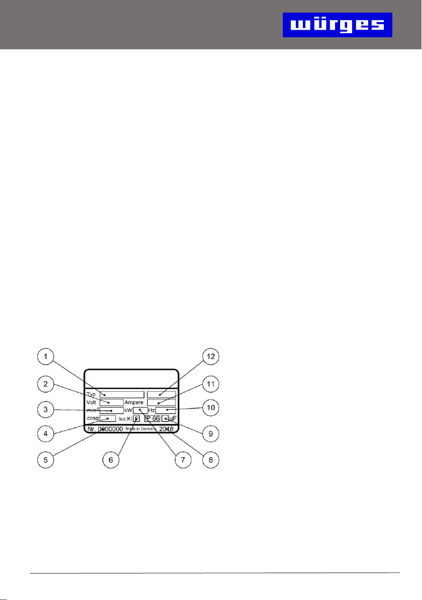
Voltage 3 ~ 230 / 400V 50Hz, 1 ~ 230V 50Hz
Special voltages from 3 ~ 42V - 3 ~ 700V 50Hz, 60Hz and 200Hz are available.
Special designs with PTC thermistors (standard for HV 75 - HV 200), anti-
condensation heating available
2-, 4-, 6, - and 8-pole versions (10- and 12-pole on request)
Low power consumption with high starting torque
The windings of sizes HV 1 & HV 2 are completely encapsulated with the housing
under vacuum. In the other sizes, the complete vibration-proof winding is vacuum
impregnated twice with special resin, not just the winding head.
All windings are equipped with phase insulation, so operation on frequency
converters is possible without hesitation.
Each winding is checked twice in our factory: 1.) after delivery and 2.) after
installation in the motor.
Tropical insulation as standard
Insulation class F (155 ° C), on request insulation class H (180 ° C)
Ambient temperature -20 ° C to + 40 ° C, with some types up to + 55 ° C

10
Designed for continuous operation (S1) with full unbalance setting (except HV 6 /
2-8 with Duty 40% S3)
Centrifugal force adjustment in steps with plug-in unbalance disks (see p. 17) or
stepless with swiveling unbalance disks (see p. 19)
The stator Frame up to and including size HV 85 are made of a special, resistant
aluminum alloy, some with cooling fins for perfect cooling. From size HV 75 made
of nodular cast iron with cooling fins for optimal elasticity and strength.
Impact-resistant protective covers cast from special aluminum or thermoformed
from electrically polished stainless steel
All sealing surfaces of the motors are machined for a perfect tightness.
All O-ring seals are securely sunk in machined grooves.
Premium rolling bearings with increased C4 internal clearance, made just for us.
Cylindrical roller bearings with increased load rating and with a spherically
grinded inner ring.
Every motor goes through a test run with full unbalance adjustment and control of
the nominal current before delivery
Painting: RAL 7016, other colors available on request (HV 0.1, HV 0.4, HV 1 and
HV 2 are unpainted)
"Made in Germany" - production since 1965 exclusively in Germany.
ISO 9001: 2015 certified by TÜV Rheinland.

11
5. Transport and Storage
Upon delivery, the motors must be checked for visible transport damage.
If the motor shows visible damage, it must not be put into
operation. The vibration motor must be returned to the
manufacturer for examination and, if necessary, repair.
The vibrator motors must be stored in closed, dry rooms at ambient temperatures
of -20 ° C to a maximum of + 60 ° C until they are installed.
Vibration motors may only be placed on their feet.
The motor must not be lifted by the attached connection cable.
The eye bolts of sizes HV 65 and HV 85 are only to be used to lift the vibration
motor.
The local accident regulations must be observed.

12
6. Installation and commissioning
6.1. Assembly / installation
Vibrating motors can be installed in any installation position. They may only be
attached to machines with flat, oil, grease and paint-free and rigid mounting
surfaces.
Surface quality:
Only screws of quality class ≥ 8.8 ISO 4014 (DIN 931) or ISO 4017 (DIN 933) and
nuts of quality class ≥ 8.8 ISO 4032 (DIN 934) may be used.
They must be secured against mechanical loosening by Schnorr washers or
similar.
The fastening screws must be checked for tightness after
approx. Two hours of operation and tightened if necessary.
Further checks should be carried out daily!
Tightening torques for fastening screws:
M5
M8
M10
M12
M16
M20
M22
M24
M27
M30
M36
8
Nm
30
Nm
55
Nm
90
Nm
150
Nm
280
Nm
370
Nm
450
Nm
1100
Nm
1350
Nm
2500
Nm
Always tighten the fastening screws crosswise.
For elongated holes (e.g. HV 0.4, HV 1, HV 2 and HV 6), ISO 7089 (DIN 125)
washers must also be used.

13
6.2 Electrical connection
When working on the vibration motors, they must be safely
disconnected from the electrical network. Proceed as follows:
1. Turn power off
2. Secure against being switched on again
3. Check that there is no voltage
4. Let the motor cool off
5. Ground the motor
The electrical connection may only be carried out by a qualified electrician or
electrically trained person according to EN-60204-1.
The mains voltage may deviate by + - 5% and the mains frequency by + - 2%
from the data on the nameplate. The device may only be connected to a power
system that complies with VDE regulations.
Connection diagram for three-phase current 3 ~ phase (230 / 400V 50Hz)
Delta connection (low voltage)
Star connection (high voltage)
Δ
Y
z.B. 3~230V
z.B. 3~400V
Connection diagram for direct current (HV 2 GL)
24V DC / 12V DC

14
Connection diagram with PTC thermistor (use cable 7G1.5²)
HV 1 –HV 85
HV 40, HV 75, ab HV 100
Star-delta connection not possible
Star-delta connection possible
Connection diagram High Frequency
42V 200Hz, 110V 200Hz, 250V 200Hz
To prevent possible overloading, each vibrator must have its own motor
protection switch, the tripping current of which must be set in accordance with the
data on the nameplate.
If there are two, counter rotating motors running, it must be ensured that if one
motor fails, both motors switch off at the same time
(see circuit diagram on page 24).
Only flexible cables may be used for connection. We recommend the following
cable types:
HV 0,4 - HV 1: H 05 RN-F 4G0,75²
HV 2 - HV 85: H 07 RN-F 4G1,5²
from HV 75: NSHTÖU-J 4G1,5² (or H 07 RN-F 4G1,5²)
HV 2 GL: H 07 BQ-F 2x2,5²
HF: H 07 RN-F 4G1,5²
Plastic cables are unsuitable. Attach isolated cable lugs to the wire ends. Under
no circumstances solder cable lugs, as vibrations can cause the stranded wire to
break near the soldering point.

15
Insert the cable into the terminal box and connect according to the previous
diagram (see page 14).
Except for HV 0.4/2, HV 0.4/2-1 and HV 0.1, these have the appropriate cables ex
works.
When tightening the cable gland nut, make sure that the cable sheath is fully
covered by the seal. If this is not followed, the cable is not firmly clamped, not
strain-relieved and not watertight.
Carefully close the terminal box with the seal again.
The motor connection cable must be laid firmly approx. 0.5 m after exiting the
motor. The first fastening point of the cable and the motor must not be able to
move against each other during operation. The connection cable must be laid in
such a way that natural vibrations are avoided and no tensile stress
he follows.
During the initial start-up, the current consumption must be checked in all three
phases. Should this be larger than the one on the nameplate
specified value can be remedied by reducing the centrifugal force (see chapter 7).
The cable must be checked from time to time for chafe marks and, if necessary,
the cause must be eliminated.
1 cable lug DIN 46237 2 washer ISO 7090
3 terminal board bolts 4 Schnorr washer type VS
5 Nut ISO 4032 6 Earthing screw M4x8 / M5x10
Maximum tightening torques for the terminal board nuts
HV 1 –HV 30
Ab HV 40
Ab HV 180
PTC Connection
M4
M5
M6
M4
1,2 Nm
2,0 Nm
3,0 Nm
1,2 Nm

16
6.3. Speed Control
With our three-phase vibrating motors, the speed can be regulated with frequency
converters.
The output power of the frequency converter should be approx. 1.5 times the
rated motor power (P1 / Pin).
Please inquire about the maximum permissible final speed for each motor type.
The speed reduction, up to approx. 20 Hz, is problem-free in any case
possible.
If the speed is increased above the value specified on the
nameplate, there is a risk of accident due to impermissibly
high centrifugal force.
The centrifugal force must be reduced!
The motors of the HF series require a frequency converter for power supply.
They can be operated with both a variable frequency and a fixed frequency.
When using a frequency converter, compliance with the EMC directive must be
observed.
In this case, we recommend using a shielded connection cable.
6.4. Permissible operating temperature
The temperature on the stator frame should not be higher than 80 ° C.
This limit can be exceeded if the current consumption is too high if the speed
specified on the nameplate is not reached. This can cause the winding to burn
out.
Possible cause is a centrifugal force that is too high for the application or an
insufficiently rigid construction.
By resetting the centrifugal force or using a device with more powerful
electric drive can help.
Ambient temperature must to be between -20 ° C and up to + 40 ° C
(for some types up to + 55°C)

17
7. Force Adjustment
Danger of crushing when setting the centrifugal force.
Make sure that the rotor shaft is fixed. The safety instructions
on page 6 must be observed!
If no special centrifugal force setting has been ordered, the motor is set to maximum
centrifugal force ex works.
The centrifugal force has a direct influence on the amplitude of the machine and
the current consumption of the motor.
To adjust the centrifugal force, dismantle both protective hoods (item 3, see p. 26
and following.) And loosen the unbalance fixation (item 30, p. 26 and following.).
7.1. Centrifugal force adjustment with plug-in
unbalance discs
For motors of size HV 0.4 to HV 15, HV 30/2, HV 55/2 and HF, the centrifugal
force is set in steps by means of plug-in unbalance disks.
The number of disks turned over must be symmetrical on both shaft ends (see
Fig. On page 18). Unbalance disks can also be removed for fine adjustment;
these must be replaced by spacers of the same thickness.
The centrifugal force is reduced by 180 ° by repositioning the unbalance disks on
both sides.
The centrifugal force of the motor is reduced in the case of a 180 ° rotated or
removed plug unbalance as follows:
Speed 2-pole, 3000 min-1,
Motor
Force
180° rotated
removed
HV 0,4/2
50 N
25 N
HV 1/2
50N
25 N
HV 2/2
220 N
110 N
HV 6/2
380 N
190 N
HV 8/2
750 N
375 N
HV 12/2
750 N
375 N
HV 15/2
750 N
375 N
HV 15/2-20
750 N
375 N
HV 15/2-25
1260 N
630 N
HV 30/2
1260 N
630 N
HV 55/2
2100 N
1050 N

18
Speed 4-pole min-1
Motor
Force
180° rotated
removed
HV 1/4
12,5 N
6,25 N
HV 2/4
55 N
27,5 N
HV 6/4
95 N
47,5 N
HV 12/4-30
187,5 N
93,75 N
HV 12/4-42
350 N
175 N
Speed 6-pole 1000 min-1
Motor
Force
180° rotated
removed
HV 6/6
42,5 N
21,25 N
HV 12/6
148,67 N
74,34 N
Speed 8-pole 750 min-1
Motor
Force
180° rotated
removed
HV 6/8
23,75 N
11,88 N
HV 12/8
87,33 N
43,67 N
HF 6000 min, 200 Hz, 3000 min-1 200 Hz
Motor
Force
180° rotated
removed
HF 2
880 N
440 N
HF 6/4
1525 N
762,5 N
HF 6/8
380 N
190 N
HF 8
1525 N
762,5 N
HF 15
2400 N
1200 N
After the centrifugal force has been set, the motor shaft, in the case of motors
with ball bearings, must be checked for ease of movement. If the shaft is stiff, you
schould hit the last tightened one lightly with a mallet
Screw are given to loosen the tension of the ball bearings.
Maximum tightening torques for the screws at the shaft end
HV 0,4/2
M5
4 Nm
HV 1
M5
4 Nm
HV 2
M 8
15 Nm
Ab HV 6
M10
20 Nm

19
7.2. Centrifugal force adjustment with swivel
unbalance discs
From size HV 12/4-60 (exception HV 30/2 and HV 55) the centrifugal force is
adjusted by turning the two outer unbalance disks.
The percentage centrifugal force can be either:
a) read off the scale on the shaft. One division corresponds to 10%.
or
b) read off the back (fixed) unbalance on the etched scale. One division
corresponds to 5%
The setting must be symmetrical (see illustration on page 20).

20
After the centrifugal force has been set, loosened screws
must be fastened again and the protective covers
reassembled (for tightening torques see below). Otherwise
there is a risk of accident! In order to guarantee the tightness
of the motor, it is important to ensure that the seals are intact
when dismantling and assembling the protective covers.
Damaged seals must be replaced.
Operating the vibrator motors without unbalance discs
is not permitted.
Tightening torques for the screws in the protective hoods
Tightening torques of the screws to fix the unbalance discs
M5
M6
M10
M12
4,0 Nm
6,0 Nm
20,0 Nm
30,0 Nm
M10
M12
M16
M20
M24
40,0 Nm
50,0 Nm
140,0 Nm
280,0 Nm
560,0 Nm
This manual suits for next models
6
Table of contents
Popular Industrial Equipment manuals by other brands

Brano
Brano Z 500 L Operation manual

Wilo
Wilo SiBoost Smart Series Installation and operation instructions

ABB
ABB GridShield 3P Installation, operation and maintenance manual

Parker
Parker 2003-IP-00 Technical manual

PennBarry
PennBarry Domex Operation & maintenance manual

Sealey
Sealey ADT200 quick start guide

Suspa
Suspa ELS3-500S-BTU-Q-HeavyDuty installation instructions

Carl Valentin
Carl Valentin DYNACODE II Quick reference guide

Reflex
Reflex Fillcontrol Auto operating instructions

Jäger
Jäger Z33-D060.02 K2,5a manual

SCHUNK
SCHUNK GSM-P Series Assembly and operating manual

Showa Denki
Showa Denki Mistresa CRM-S Series Operation manual