Würth master K 200 User manual

Kompressor K 200, K 280, K 400
Compressor K 200, K 280, K 400
Compresseur K 200, K 280, K 400
Compresor K 200, K 280, K 400
Compressor K 200, K 280, K 400
Kompressor K 200, K 280, K 400
Compressor K 200, K 280, K 400
Kompressor K 200, K 280, K 400
Συµπιεστής K 200, K 280, K 400
Kompresör K 200, K 280, K 400
Originalbetriebsanleitung
Original instructions
Istruzioni originali
Notice originale
Manual original
Manual original
Oorspronkelijke gebruiksaanwijzing
Original brugsanvisning
Original driftsinstruks
Alkuperäiset ohjeet
Bruksanvisning i original
Πρωττυπο οδηγιών χρήσης
Orijinal iµletme talimat∂
K200_400.book Seite 1 Mittwoch, 6. Mai 2009 7:48 07

D
GB
I
F
E
P
NL
DK
N
FIN
S
GR
TR
............................... 6... 11
.............................. 12... 17
................................ 18... 23
................................ 24... 29
................................ 30... 35
................................ 36... 41
................................ 42... 47
................................ 48... 53
................................ 54... 59
................................ 60... 65
................................ 66... 71
................................ 72... 77
................................ 78... 83
K200_400.book Seite 2 Mittwoch, 6. Mai 2009 7:48 07

K200_400.book Seite 1 Mittwoch, 6. Mai 2009 7:48 07

WÜRTH • 701 2 BA 0003 • K200 - K400 • Bildseiten • OSW 03/00
A
4
3
13 12
17
18
2
1 5 6 7 8 9 10
11
16 151920 14
K200_400.book Seite 4 Mittwoch, 6. Mai 2009 7:48 07

B
113 20
3
91074
2
17 16 8 19 18 14 12 11
15
K200_400.book Seite 5 Mittwoch, 6. Mai 2009 7:48 07

6
Gerätekennwerte
Kompressor K 200 K 280 K 400
Artikelnummer 701 220 701 228 701 240
Ansaugluftmenge 200 l/min 284 l/min 366 l/min
Effektive Liefermenge 115 l/min 152 l/min 180 l/min
Aufnahmeleistung 1,1 kW 2,2 kW 2,2 kW
Leerlaufdrehzahl 2850 min
-1
2850 min
-1
2850 min
-1
Ölmenge 0,1 l 0,35 l 0,44 l
Ölsorte ISO 100 ISO 100 ISO 100
Nennspannung 230 V 230 V 230 V
Isolationsklasse F F F
Schutzklasse
/ II / II / II
Höchstdruck 8 bar 10 bar 10 bar
Behälterinhalt 9,5 l 20 l 50 l
Zylinderbohrung 47 mm 55 mm 47 mm
Hub 37 mm 42 mm 37 mm
Elektr. Absicherung 8 A 10 A 16 A
Umgebungstemperatur +5 - +40 °C +5 - +40 °C +5 - +40 °C
Länge/Breite/Höhe 410/340/630 mm 480/410/800 mm 880/350/700 mm
Gewicht ca. 21 kg 33 kg 46 kg
Zu Ihrer Sicherheit
Gefahrloses Arbeiten mit dem
Gerät ist nur möglich, wenn Sie die
Bedienungsanleitung und die
Sicherheitshinweise vollständig
lesen und die darin enthaltenen
Anweisungen strikt befolgen.
Vor jeder Benutzung Gerät, Kabel
und Stecker überprüfen. Werden
Schäden festgestellt, das Gerät nicht
weiter benutzen. Reparatur nur von
einem Fachmann durchführen las-
sen. Gerät nie selbst öffnen.
❏Kompressoren dürfen nur von unterwiesenen
Personen bedient und gewartet werden.
❏Der Betreiber dieses Gerätes muss für die
Beachtung der geltenden Vorschriften Sorge
tragen, insbesondere für die Einhaltung der
Prüffristen für den Druckluftbehälter sowie die
Unfallverhütungsvorschriften VGB 16.
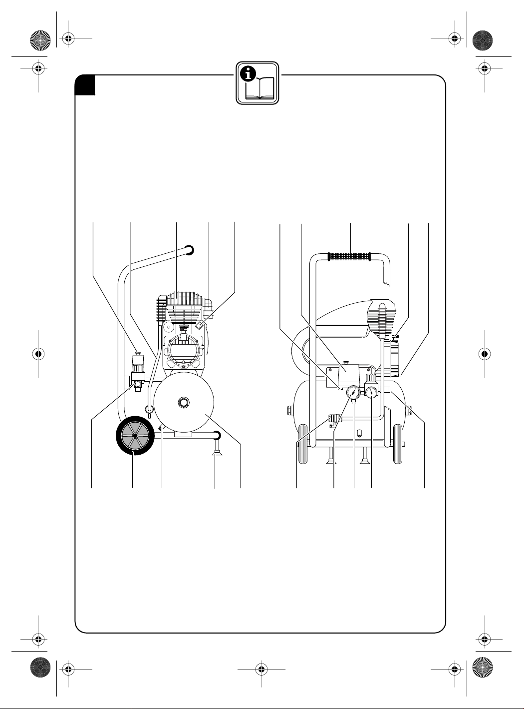
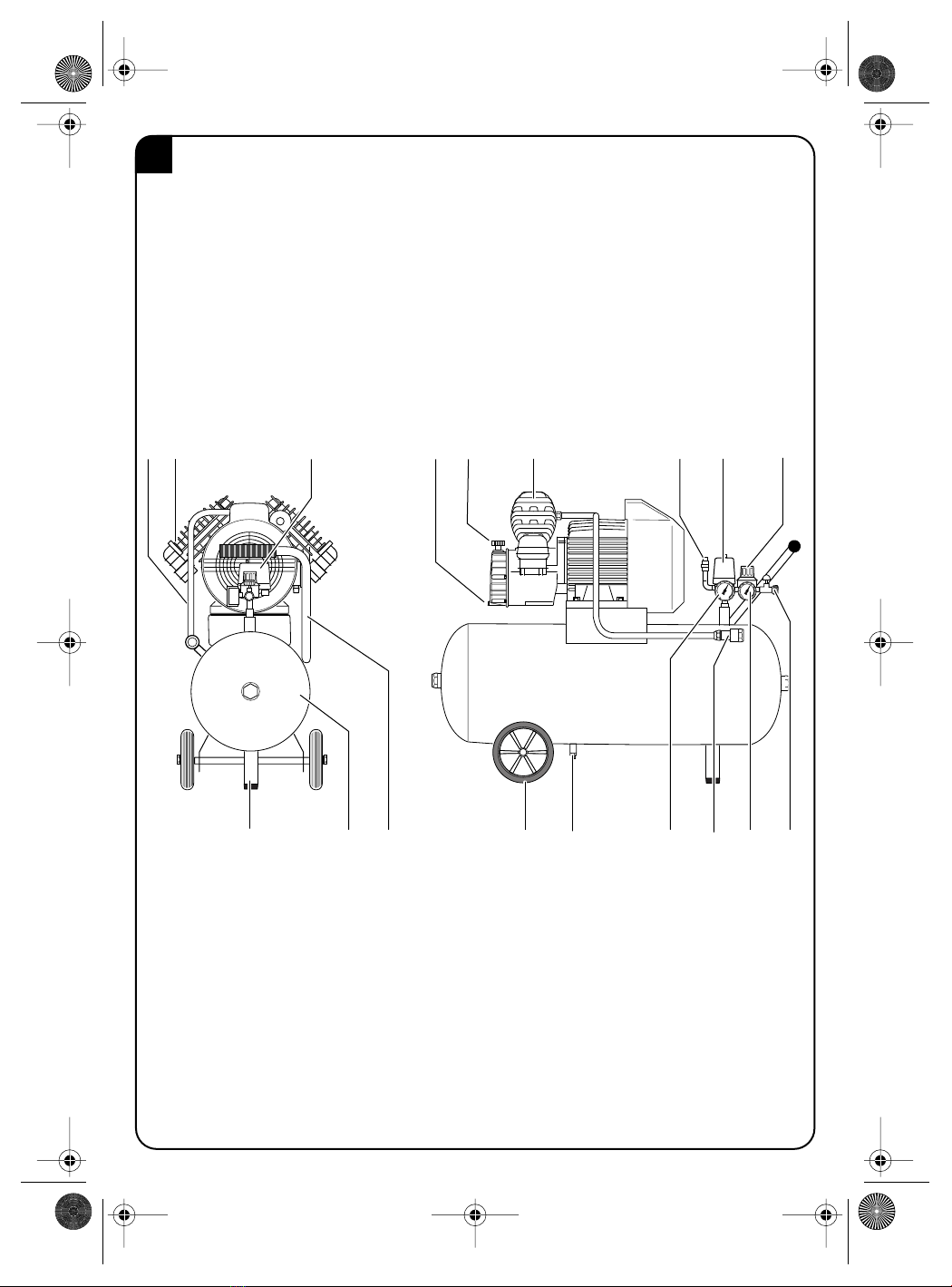
❏Das Sicherheitsventil 13 ist gegen Verstellen
gesichert. Der werkseitig eingestellte Abblase-
druck darf nicht verändert werden.
❏An dem Gerät, insbesondere dem Druckluftbe-
hälter 16, dürfen keine baulichen Veränderun-
gen vorgenommen werden.
❏Vorsicht Verbrennungsgefahr! Durch den
Betrieb der Anlage erhitzen sich Aggregat und
Druckleitung 2.
❏Keine entflammbaren Gegenstände in die
Nähe des Kompressors bringen.
❏Kinder und Tiere vom Arbeitsbereich fernhal-
ten, um Verletzungen durch die an den Kom-
pressor angeschlossenen Geräte zu vermeiden.
❏Kompressor nicht ohne Luftfilter betreiben.
❏Kompressor nicht bewegen, wenn Behälter
unter Druck steht.
❏Vor allen Arbeiten am Gerät den Netzstecker
ziehen und die Anlage drucklos machen.
❏Nur Original-Würth-Zubehör verwenden!
D
☞Weitere Sicherheitshinweise siehe Beilage
K200_400.book Seite 6 Mittwoch, 6. Mai 2009 7:48 07

7
1
Ein-/Ausschalter
2
Druckleitung
3
Kompressoraggregat
4
Ansaugfilter
5
Manueller Motorschutz
6
Entlastungsventil
7
Druckschalter
8
Griff
9
Öleinfüllstutzen
10
Ölablassschraube
11
Luftablasshahn
12
Manometer für Arbeitsdruck
13
Sicherheitsventil
14
Manometer für Behälterdruck
15
Rückschlagventil
16
Behälter
17
Schwingungsdämpfer
18
Kondenswasserablasshahn
19
Räder
20
Druckminderer
Abgebildetes oder beschriebenes Zubehör gehört teilweise
nicht zum Lieferumfang.
Das Gerät ist bestimmt zum Erzeugen von kompri-
mierter atmosphärischer Luft für gewerbliche und
industrielle Zwecke: Zur Verwendung als Arbeitsluft
für den Antrieb von Werkzeugen, als Blasluft z. B.
zum Lackieren oder als Steuerluft für Anlagen und
Vorrichtungen.
Für Schäden bei nicht bestimmungsgemäßen
Gebrauch haftet der Benutzer.
– Die Ansaugluft muss frei sein von aggressiven
und entzündlichen Bestandteilen.
– Vor jeder Inbetriebnahme mit Ölmessstab den
Ölstand prüfen und ggf. nachfüllen.
– Verlängerungskabel bis 25 m Länge müssen ei-
nen Querschnitt 1,5 mm
2
haben. Darüberhin-
ausgehende Längen erfordern 2,5 mm
2
. Ein zu
geringer Leiterquerschnitt bewirkt einen Span-
nungsabfall, wodurch ein sicheres Anlaufen des
Elektromotors nicht gewährleistet ist. Kabeltrom-
meln müssen ganz abgewickelt werden.
– Nie den Netzstecker ziehen, während der Motor
läuft. Nach Ausfall der Netzspannung das Gerät
am Ein-/Ausschalter
1
ausschalten und bei
Spannungswiederkehr erneut einschalten.
– Die maximale Förderleistung des Gerätes nicht
überschreiten (20 Schaltungen pro Stunde). Bei
Überlastung löst der Druckschalter
7
aus. Bei ei-
nem Zeitverhältnis von 1 : 3 zwischen Pause und
Betrieb ist das Gerät optimal ausgelastet.
Die Würth-Geräte der Baureihe K 200, K 280 und
K 400 sind Kompressoren mit direkt am Verdichter
angeflanschten Antriebsmotor. Über den Ansaugfil-
ter
4
, der als Geräuschdämpfer dient, wird Frischluft
angesaugt und im Zylinder verdichtet. Das im Zylin-
derkopf eingebaute Kompressorventil steuert das
Ansaugen und Ausschieben der Luft. Über die
Druckleitung
2
und das Rückschlagventil
15
strömt
die Druckluft in den Druckluftbehälter.
Der Kompressor arbeitet im Aussetzbetrieb. Nach
Erreichen des Maximaldruckes schaltet der Druck-
schalter
7
den Kompressor ab und bei Absinken des
Druckes auf ca. 8 bar (bei K 200 ca. 6 bar) erneut
ein.
Geräteelemente
Bestimmungsgemäßer
Gebrauch
Geräteschutz
Funktion des Kompressors
K200_400.book Seite 7 Mittwoch, 6. Mai 2009 7:48 07

8
Netzspannung beachten:
Die Spannung der Strom-
quelle muss mit den Angaben auf dem Typschild des
Gerätes übereinstimmen. Mit 230 V beschriftete
Geräte können auch an 220 V betrieben werden.
Den Ölstand am Ölmessstab kontrollieren.
Aufstellungsort
Stellen Sie Ihren Kompressor waagrecht an einem
kühlen, trockenen, möglichst staubfreien und saube-
ren Ort auf. Die maximal zulässige Neigung beträgt
15°. Achten Sie besonders auf gute Kühlung der
Anlage. Dies wird in erster Linie durch ungehinderte
Frischluftzufuhr erreicht.
Wichtig ist, dass die Temperatur am Aufstellungsort
nicht unter +5 °C absinkt und nicht über +40 °C
ansteigt. Wärmeabstrahlende Geräte und Leitungen
in der Umgebung des Kompressors sind zu vermei-
den.
Druckluftanschluss
– Den Druckluftschlauch am Verbraucher und am
Druckminderer
20
anschließen.
– Feststellring (bzw. Kippschalter) am Druckminde-
rer
20
lösen und den erforderlichen Arbeitsdruck
am Drehgriff einstellen:
Rechtsdrehung - Arbeitsdruck wird größer,
Linksdrehung - Arbeitsdruck verringert sich.
Für verschiedenen Arbeiten gelten folgende
Richtwerte:
Farbspritzgeräte.................................2 - 4 bar
Antrieb für Druckluftwerkzeuge ...........5 - 7 bar
Achten Sie auf die Angaben in den Bedienungs-
anleitungen der verwendeten Verbraucher.
– Den Druckminderer mittels Feststellring (bzw.
Kippschalter) gegen unbeabsichtigtes Verstellen
sichern.
– Nach Gebrauch den Druckminderer
20
auf „0”
zurückstellen.
Einschalten
– Den Kompressor am Ein-/Ausschalter
1
ein-
schalten.
– Der Kompressor ist mit einer automatischen Dru-
ckentlastung ausgerüstet. Erreicht der Nenndruck
im Druckluftbehälter
16
10 bar (bei K 200
8 bar), wird der Motor automatisch abgeschaltet
und die Druckleitung
2
zwischen Verdichter und
Rückschlagventil
15
entlüftet. Damit ist ein druck-
loser Wiederanlauf des Kompressors sicherge-
stellt.
Die Druckentlastung funktioniert nicht, wenn
während des Betriebs die Netzspannung aus-
fällt oder der Netzstecker gezogen wird. Die
Druckentlastung ist jedoch wieder wirksam,
wenn der Kompressor am Druckminderer
20
auf „0” gestellt wird.
Ausschalten
– Den Kompressor am Ein-/Ausschalter
1
aus-
schalten.
Inbetriebnahme
K200_400.book Seite 8 Mittwoch, 6. Mai 2009 7:48 07

9
Vor allen Arbeiten am Gerät die Luft aus dem
Behälter ablassen und das Gerät ausschalten.
Gerät stets sauberhalten.
Ansaugfilter 4
– Filtereinsatz aus Schaumstoff oder Papier bei
Verschmutzung wechseln.
– Filtereinsatz aus Drahtgeflecht in Waschöl aus-
waschen, trocknen, wieder einölen und weiter
verwenden.
Kondensat ablassen
– Vorsicht, der Druckluftbehälter
16
steht unter
Druck. Einen Auffangbehälter unterstellen. Öff-
nen Sie den Kondensatablasshahn
18
am Boden
des Druckluftbehälters vorsichtig eine 1/2 Um-
drehung und lassen Sie das Kondensat ab.
– Kontrollieren Sie den Kondensatspiegel im Klar-
sichtbehälter des Druckminderers
20
regelmä-
ßig. Er darf nicht die obere Markierung über-
schreiten. Zum Kondensat ablassen muss der an
der Unterseite des Druckminderers befindliche
Knopf unter Druck 1/2 Umdrehung geöffnet wer-
den.
Ölwechsel
– Der Ölwechsel sollte grundsätzlich im betriebs-
warmen Zustand erfolgen.
– Auffanggefäß unterstellen und Ölablassschrau-
be
10
öffnen. Vorsicht Verbrennungsgefahr am
heißen Öl!
– Ölablassschraube
10
schließen und über den
Öleinfüllstutzen
9
Öl der Klasse ISO100 auffül-
len.
Wartungsintervalle
Sollte das Gerät trotz sorgfältiger Herstell- und Prüf-
verfahren einmal ausfallen, ist die Reparatur von
einer autorisierten Kundendienststelle für
Würth-Elektrowerkzeuge ausführen zu lassen.
Bei allen Rückfragen und Ersatzteilbestellungen bitte
unbedingt die 6-stellige Artikelnummer laut Typ-
schild des Gerätes angeben.
Wartung und Pflege
Pflege - regelmäßig Kühlrippen
von Zylinder und
Druckleitung
2
reinigen,
Schaugläser der
Manometer reinigen
Schraubverbindungen - einmalig nach 50
Betriebsstunden
nachziehen
Ölstandskontrolle - täglich, bzw. bei jeder
Inbetriebnahme
Ölwechsel - erstmalig nach 5
Betriebsstunden
- regelmäßig nach 100
Betriebsstunden, jedoch
mindestens einmal alle
6 Monate
Kondensat ablassen - mindestens wöchentlich
- bei Bedarf täglich
Ansaugfilter prüfen - wöchentlich
Ansaugfilter reinigen - monatlich, bei hoher
Staubbelastung öfter
Ansaugfilter wechseln - bei starker
Verschmutzung oder
Beschädigung
Rückschlagventil
reinigen - alle 2 Jahre
Achtung:
Behälterdruck ablassen!
empfohlene
Überprü-fung gemäß
DruckbehV
-
-
5-jährlich innere
Prüfung
10-jährlich
Druckprüfung
K200_400.book Seite 9 Mittwoch, 6. Mai 2009 7:48 07

10
Der Kompressor läuft nicht an.
– Der Druckschalter
7
hat ausgelöst. > Kurze Zeit warten, Wiedereinschalttaste drücken
und Ein-/Ausschalter
1
betätigen, um Kompres-
sor einzuschalten. Löst der Motorschutz erneut
aus, Service anrufen.
– Das Manometer
14
zeigt höherern Druck als
7,5 bar (bei K 200 5 bar) (Einschaltdruck). > Druck ablassen, bis der Druckschalter 7 einschal-
tet.
– Netzspannung fehlt. > Überprüfen der elektrischen Leitungen, etc.
Kompressor läuft ununterbrochen.
– Ansaugfilter 4 verschmutzt. > Filter reinigen oder erneuern.
– Der Kompressor ist überlastet. > Druckluftbedarf reduzieren.
– Leckage im nachfolgenden Leitungssystem. > Undichtigkeit beseitigen.
– Kompressor defekt. > Service anrufen.
Der Kompressor läuft bei Erreichen des Einschaltdruckes kurz an und schaltet dann automatisch ab.
– Der Kompressor war nicht druckentlastet, weil
während des Betriebes die Stromzufuhr unterbro-
chen wurde.
> Kompressor am Ein-/Ausschalter 1 ausschalten
und danach wieder einschalten.
– Ein-/Ausschalter 1 defekt. > Service anrufen.
– Netzanschlussleitung hat unzulässige Länge bzw.
zu geringen Leiterquerschnitt > Kabel max. 25 m bei 1,5 mm2Leiterquerschnitt.
Bei Stillstand entweicht längere Zeit Druckluft über das Entlastungsventil 6 unter dem Druckschalter 7,
bis zum Erreichen des Einschaltdruckes.
– Rückschlagventil 15 undicht oder defekt. > Service anrufen.
Bei Betrieb entweicht Druckluft über das Entlastungsventil 6.
– Entlastungsventil 6 undicht. > Service anrufen.
Kompressor schaltet häufig ein.
– Kondenswasser im Druckluftbehälter 16. > Kondensat entleeren.
– Kompressor überlastet. > Druckluftbedarf reduzieren.
– Nachlassende Leistung wegen abgenützter Ven-
tilplatte. > Service anrufen.
Das Sicherheitsventil 13 bläst ab.
– Behälterdruck höher als der Öffnungsdruck des
Sicherheitsventils 13.> Druckschalter 7 muss neu eingestellt bzw. erneu-
ert werden, Service anrufen.
Fehlersuche
K200_400.book Seite 10 Mittwoch, 6. Mai 2009 7:48 07

11
Umweltschutz
Elektrowerkzeuge, Zubehör und Verpackungen sol-
len einer umweltgerechten Wiederverwertung zuge-
führt werden.
Nur für EU-Länder:
Werfen Sie Elektrowerkzeuge nicht
in den Hausmüll!
Gemäß der Europäischen Richtlinie
2002/96/EG über Elektro- und
Elektronik-Altgeräte und ihrer
Umsetzung in nationales Recht müssen nicht mehr
gebrauchsfähige Elektrowerkzeuge getrennt gesam-
melt und einer umweltgerechten Wiederverwertung
zugeführt werden.
Gewährleistung
Für dieses Würth-Gerät bieten wir eine Gewährleis-
tung gemäß den gesetzlichen/länderspezifischen
Bestimmungen ab Kaufdatum (Nachweis durch
Rechnung oder Lieferschein). Entstandene Schäden
werden durch Ersatzlieferung oder Reparatur besei-
tigt.
Schäden, die auf natürliche Abnutzung, Überlas-
tung oder unsachgemäße Behandlung zurückzufüh-
ren sind, werden von der Gewährleistung ausge-
schlossen.
Beanstandungen können nur anerkannt werden,
wenn Sie das Gerät unzerlegt einer Würth-Nieder-
lassung, Ihrem Würth-Außendienstmitarbeiter oder
einer Würth-autorisierten Kundendienststelle für
Elektro- und Druckluftwerkzeuge übergeben.
Messwerte ermittelt entsprechend EN 50 144.
Der A-bewertete Schalldruckpegel des Gerätes
beträgt typischerweise:
K 200: 79 dB (A)
K 280: 80 dB (A)
K 400: 83 dB (A).
Konformitätserklärung
Wir erklären in alleiniger Verantwortung, dass die-
ses Produkt mit den folgenden Normen oder norma-
tiven Dokumenten übereinstimmt:
EN 1012-1, EN 60 204-1, EN 60 335-1,
EN 50 081-1, EN 50 082-2 gemäß den Richtlinien
98/37/EG (bis 28.12.2009), 2006/42/EG
(ab 29.12.2009), 97/23/EG, 2000/14/EG,
2006/95/EG, 89/336/EWG, 87/404/EWG,
93/68/EWG.
09
Technische Unterlagen bei:
Adolf Würth GmbH & Co. KG
Künzelsau
P. Zürn A. Kräutle
Geräusch-/
Vibrationsinformation
Änderungen vorbehalten
K200_400.book Seite 11 Mittwoch, 6. Mai 2009 7:48 07

12
Tool Specifications
Compressor K 200 K 280 K 400
Article number 701 220 701 228 701 240
Intake air quantity 200 l/min 284 l/min 366 l/min
Effective delivery quantity 115 l/min 152 l/min 180 l/min
Rated input 1.1 KW 2.2 kW 2.2 kW
No-load speed 2850 rpm 2850 rpm 2850 rpm
Oil quantity 0.1 l 0.35 l 0.44 l
Oil type ISO 100 ISO 100 ISO 100
Rated voltage 230 V 230 V 230 V
Insulation class F F F
Safety class / II / II / II
Maximum pressure 8 bar 10 bar 10 bar
Reservoir content 9.5 l 20 l 50 l
Cylinder bore 47 mm 55 mm 47 mm
Stroke 37 mm 42 mm 37 mm
Fuse protection 8 A 10 A 16 A
Ambient temperature +5 - +40 °C +5 - +40 °C +5 - +40 °C
Length/width/height 410/340/630 mm 480/410/800 mm 880/350/700 mm
Weight approx. 21 kg 33 kg 46 kg
For Your Safety
Working safely with this machine
is possible only when the operating
and safety information are read
completely and the instructions
contained therein are strictly follo-
wed.
Before each use of the machine,
check the cable and plug. If dam-
age is detected, do not use the ma-
chine. Have repairs performed only
by a qualified technician. Never
open the machine yourself.
❏Compressors should only be operated and serv-
iced by trained personnel.
❏The operator of this machine is responsible for
observing the valid instructions, and in particu-
lar for adhering to the scheduled testing times
for the compressed air reservoir and the regula-
tions for the prevention of accidents (VGB 16).
❏The safety valve 13 has been secured against
becoming altered. The blow-off pressure pre-set
by the manufacturer must not be changed.
❏No changes may be made on the machine by
the customer, in particular, the compressed air
reservoir 16.
❏Caution! Danger of burning! When the plant is
in operation, the unit and pressure tube 2 be-
come hot.
❏Do not place any inflammable objects in the vi-
cinity of the compressor.
❏Keep children and animals away from the op-
erating area and thereby prevent any injuries
being caused by equipment connected to the
compressor.
❏Do not operate the compressor without an air
filter.
❏Do not move the compressor if the reservoir is
under pressure.
❏Before commencing any work on the machine,
pull out the mains plug and ensure that the plant
is depressurised.
❏Use only original Würth parts and accessories.
GB
☞For further notes on safety refer to enclosed Sheet
K200_400.book Seite 12 Mittwoch, 6. Mai 2009 7:48 07

13
1 ON/OFF switch
2 Pressure lead
3 Compressor unit
4 Suction filter
5 Manual motor protection
6 Relief valve
7 Pressure switch
8 Handle
9 Oil filler opening
10 Oil drain plug
11 Air escape cock
12 Manometer for working pressure
13 Safety valve
14 Manometer for reservoir pressure
15 Non-return valve
16 Reservoir
17 Vibration damper
18 Condensation water drain cock
19 Wheels
20 Pressure reducer
Not all of the accessories illustrated or described are in-
cluded as standard delivery.
The machine is designed for generating compressed
atmospheric air for commercial and industrial pur-
poses, i. e. for use as working air for driving tools,
as blowing air, e.g. for painting, or as control air for
plants and equipment.
For damage caused by usage other then intended,
the user is responsible.
– The intake air must be free from any aggressive
or inflammable particles.
– Before each operation, check the oil level using
the oil dip stick and, if necessary, replenish.
– Extension cables of up to 25 m in length must
have a cross-section of 1.5 mm2. Any lengths be-
yond this require 2.5 mm2. If the cross-section of
the conductor is too small, this will cause a volt-
age drop and there is no guarantee that the mo-
tor will start correctly. Cable reels must be fully
unwound.
– Never pull out the mains plug while the motor is
running. If the mains voltage fails, switch the ma-
chine off using the On/Off switch 1 and when
the voltage has been restored, switch on again.
– Do not exceed the maximum delivery output of
the machine (20 switchings per hour). At over-
load the pressure switch 7 is actuated. The ma-
chine is utilised optimally with a pause/operation
time ratio of 1 : 3.
The Würth machines of model series K 200, K 280
and K 400 are compressors with drive motors flang-
ed directly onto the compressor. Fresh air is drawn
in via the intake filter 4 serving as a sound absorber,
and compressed in the cylinder. The compressor
valve integrated in the cylinder head controls the
suction and emission of the air. The compressed air
flows into the compressed air reservoir via the pres-
sure lead 2 and the non-return valve 15.
The compressor functions in intermittent operation.
Upon reaching the maximum pressure the pressure
switch 7 switches the compressor off and when the
pressure falls to approx. 8 bar (for the K 200 ap-
prox. 6 bar) switches it on again.
Operating Controls
Use as Intended
Equipment Protection
Compressor Function
K200_400.book Seite 13 Mittwoch, 6. Mai 2009 7:48 07

14
Always use the correct supply voltage: The power
supply voltage must match the information quoted
on the tool identification plate. Tools with a rating of
230 V can also be connected to a 220 V supply.
Check the oil level on the oil dip-stick.
Installation
Install your compressor in a horizontal position in a
cool, dry, place exposed to as little dust as possible.
The maximum permissible angle of tilt is 15°. Pay
special attention to good cooling of the plant. This is
mainly achieved by ensuring a free passage of fresh
air.
It is important that the temperature at the location
does not fall below +5 °C and does not exceed
+40 °C. Devices and leads that give off heat should
be avoided in the environment.
Compressed air connection
– Connect the compressed air lead to the consumer
and pressure reducer 20.
– Loosen the locking ring (or snap switch) on the
pressure reducer 20 and set the required work-
ing pressure on the turning grip:
– clockwise turn: working pressure increases,
– anti-clockwise turn: working pressure decreases.
– The following reference values apply for different
kinds of work:
Paint-spraying devices........................2 - 4 bar
Drive for pneumatic tools ....................5 - 7 bar
– Observe the information in the operating instruc-
tions of the consumers used.
– Secure the pressure reducer against unintention-
al alteration using the locking ring (or snap
switch).
– After use set the pressure reducer 20 back to “0”.
Switching on
– Switch the compressor on using the On/Off
switch 1.
– The compressor is fitted with an automatic pres-
sure relief. If the rated pressure in the compressed
air reservoir 16 reaches 10 bar (for the K 200
8 bar), the motor is automatically switched off
and the pressure lead 2 between the compressor
and non-return valve 15 is vented. A pressure-
free re-start of the compressor is thereby guaran-
teed.
The pressure relief will cease to function if the
mains voltage fails during operation, or if the
mains plug is disconnected. The pressure relief
becomes effective again, however, if the com-
pressor on the pressure reducer 20 is set to “0”.
Switching off
– Switch the compressor off using the On/Off
switch 1.
Initial Operation
K200_400.book Seite 14 Mittwoch, 6. Mai 2009 7:48 07

15
Before commencing any work on the machi-
ne, discharge the air from the reservoir and
switch the machine off.
Always keep the machine clean.
Suction filter 4
– Change the foamed-plastic or paper-filter insert
when dirty.
– Wash out the wire-gauze filter insert in wash oil
and then dry, re-lubricate and re-use.
Draining the condensation
– Caution! The compressed air reservoir 16 is un-
der pressure. Place a collecting vessel under-
neath. Carefully open the condensation water
drain cock 18 on the base of the compressed air
reservoir by making a 1/2 turn and drain the
condensation.
– Check the condensation level regularly in the
transparent container of the pressure reducer 20.
It must not exceed the upper marking. For drain-
ing the condensation, the knob located on the un-
derside of the pressure reducer must be opened
a 1/2 turn under pressure.
Oil change
– As a basic rule the oil change should be carried
out under hot-running conditions.
– Place the collecting vessel underneath and open
the oil drain plug 10. Caution! Danger of burn-
ing from the hot oil!
– Close the oil drain plug 10 and fill up with oil of
class ISO 100 through the oil filler opening 9.
Maintenance intervals
If the machine should happen to fail despite the care
taken in manufacture and testing, repair should be
carried out by an authorised customer services
agent for Würth power tools.
For all correspondence and spare parts orders, al-
ways include the 6 digit order number of the ma-
chine!
Maintenance and Cleaning Care - change the cooling fins
of the cylinder and
pressure lead 2
regularly; clean the
manometer sight
glasses
Screwing connections - tighten once after 50
hours of operation
Checking the oil level - daily, or before each
use
Changing the oil -for the first time after 5
hours of operation
- regularly after 100
hours of operation,
however, at least once
every 6 months
Draining the
condensation - at least weekly
- if required, daily
Checking the intake
filter - weekly
Cleaning the intake
filter - monthly, and more
often if exposed to
large amounts of dust
Changing the intake
filter - if extremely dirty or
damaged
Cleaning the non-return
valve - every 2 years
Warning! discharge the
reservoir pressure!
Recommended check
according to pressure
reservoir instructions
-
-
every 5 years - internal
check
every 10 years -
pressure check
K200_400.book Seite 15 Mittwoch, 6. Mai 2009 7:48 07

16
The compressor fails to start.
– The pressure switch 7 is actuated. > Wait a short while. Press the re-starting switch
and press the On/Off switch 1 to switch on the
compressor. If the motor protection is actuated
again, contact the customer service.
– The manometer 14 shows a pressure greater
than 7.5 bar (for the K 200 5 bar) (cutting-in
pressure).
> Release pressure until the pressure switch 7
switches on.
– Mains voltage fails. > Check the electrical leads, etc.
Compressor runs uninterruptedly.
– Intake filter 4 is dirty. > Clean filter or replace.
– The compressor is overloaded. > Reduce the compressed air requirement.
– Leakage in the subsequent lead system. > Eliminate leakage.
– Compressor is defective. > Contact the customer service.
The compressor runs for a short time when reaching the cutting-in pressure but then automatically
switches off.
– The compressor was not de-pressurised because
the electrical feed was interrupted during opera-
tion.
> Switch the compressor off using the On/Off
switch 1 and then switch it on again.
– On/Off switch 1 is defective. > Contact the customer service.
– The length of the mains connection lead is not
permissible or the conducting cross-section is too
small.
> Lead length max. 25 m with a cross-section of
1.5 mm2.
At standstill, compressed air escapes for a longer period through relief valve 6 under pressure switch 7,
until the cutting-in pressure is reached.
– Non-return valve 15 has a leak or is defective. > Contact the customer service.
During operation compressed air escapes through relief valve 6.
– Relief valve 6 has a leak. > Contact customer service.
Compressor often switches on.
– Condensation water in the compressed air reser-
voir 16.> Drain condensation water.
– Compressor is overloaded. > Reduce compressed air requirement.
– Reduced performance due to worn valve plate. > Contact customer service.
Safety valve 13 blows off.
– Reservoir pressure is greater than the opening
pressure of the safety valve 13.– Pressure switch 7 must be re-set or changed;
contact customer service.
Error Detection
K200_400.book Seite 16 Mittwoch, 6. Mai 2009 7:48 07

17
Power tools, accessories and packaging should be
sorted for environmental-friendly recycling.
Only for EC countries:
Do not dispose of power tools into
household waste!
According to the European Directive
2002/96/EC on waste electrical
and electronic equipment and its in-
corporation into national law, power tools that are
no longer suitable for use must be separately collect-
ed and sent for recovery in an environmental-friend-
ly manner.
For this Würth machine, we provide a warranty in
accordance with statutory/country-specific regula-
tions from the date of purchase (proof of purchase
by invoice or delivery note). Damage that has oc-
curred will be corrected by replacement or repair.
Damage caused by normal wear, overloading or
improper handling is excluded from the warranty.
Claims can be accepted only when the machine is
presented undisassembled to a Würth branch office,
your Würth sales representative or a customer serv-
ice agent for Würth power tools.
Measured values determined according to
EN 50 144.
Typically the A-weighted noise levels of the tool are:
K 200: 79 dB (A)
K 280: 80 dB (A)
K 400: 83 dB (A).
We declare under our sole responsibility that this
product is in conformity with the following standards
or standardization documents: EN 1012-1,
EN 60 204-1, EN 60 335-1, EN 50 081-1,
EN 50 082-2 according to the provisions of the reg-
ulations 98/37/EG (until 28.12.2009),
2006/42/EG (from 29.12.2009), 97/23/EG,
2000/14/EG, 2006/95/EG, 89/336/EWG,
87/404/EWG, 93/68/EWG.
09
Technical file at:
Adolf Würth GmbH & Co. KG
Künzelsau
P. Zürn A. Kräutle
Disposal
Warranty
Noise/Vibration Information
Declaration of Conformity
Subject to change without notice
K200_400.book Seite 17 Mittwoch, 6. Mai 2009 7:48 07

18
Dati tecnici
Compressore K 200 K 280 K 400
Codice di ordinazione 701 220 701 228 701 240
Quantità di aria di aspirazione 200 l/min 284 l/min 366 l/min
Quantità effettiva di mandata 115 l/min 152 l/min 180 l/min
Potenza assorbita 1,1 kW 2,2 kW 2,2 kW
Numero di giri a vuoto 2850 min-1 2850 min-1 2850 min-1
Quantità di olio 0,1 l 0,35 l 0,44 l
Tipi di olio ISO 100 ISO 100 ISO 100
Tensione nominale 230 V 230 V 230 V
Classe di isolamento F F F
Classe di protezione / II / II / II
Pressione massima 8 bar 10 bar 10 bar
Capacità del serbatoio 9,5 l 20 l 50 l
Foratura del cilindro 47 mm 55 mm 47 mm
Corsa 37 mm 42 mm 37 mm
Sicurezza elettrica 8 A 10 A 16 A
Temperatura ambientale +5 - +40 °C +5 - +40 °C +5 - +40 °C
Lunghezza/larghezza/altezza 410/340/630 mm 480/410/800 mm 880/350/700 mm
Peso ca. 21 kg 33 kg 46 kg
Per la Vostra sicurezza
È possibile lavorare con la macchi-
na senza incorrere in pericoli sol-
tanto dopo aver letto completa-
mente le istruzioni per l'uso, l'opu-
scolo avvertenze per la sicurezza e
seguendo rigorosamente le istru-
zioni in esse contenute.
Prima di ogni impiego controllare la
macchina, il cavo e la spina. Non
continuare ad usare la macchina in
caso di danni e far intervenire solo
un tecnico specializzato. Mai aprire
la macchina.
❏L'operazione e la manutenzione dei compres-
sori è riservata esclusivamente a personale ap-
positamente addestrato.
❏Il gestore di questa apparecchiatura deve atte-
nersi alle relative prescrizioni vigenti ed in
modo particolare deve rispettare i termini di
controllo previsti per il serbatoio dell'aria com-
pressa così pure le relative norme antinfortuni-
stiche vigenti tipo quelle del VGB 16 (Istituto di
Assicurazione contro gli infortuni sul lavoro).
❏La valvola di sicurezza 13 è protetta contro av-
vio involontario. La pressione di scarico
dell'aria è regolata di fabbrica e non può esse-
re modificata.
❏È proibito eseguire delle modifiche costruttive
all'apparecchio. Ciò vale in modo particolare
per il serbatoio dell'aria compressa 16.
❏Attenzione: Pericolo di ustioni! Attraverso
l'esercizio dell'impianto si surriscaldano sia
l'aggregato che la tubazione della pressione 2.
❏Non avvicinare mai oggetti infiammabili al
compressore.
❏Tenere lontano dal campo operativo bambini
ed animali al fine di evitare il pericolo di inci-
denti che possono svilupparsi dal compressore
oppure dalle apparecchiature collegate.
❏Mai impiegare il compressore senza filtro
dell'aria.
❏Mai muovere il compressore quando il serbato-
io si trova sotto pressione.
❏Prima di una qualunque operazione all'appa-
recchio, estrarre la spina di rete ed eliminare la
pressione dell'impianto.
❏Usar exclusivamente acessórios originais de
Würth.
I
☞Per altre istruzioni di sicurezza si veda il foglio allegato
K200_400.book Seite 18 Mittwoch, 6. Mai 2009 7:48 07

19
1 Interruttore di inserimento/disinserimento
2 Tubazione della pressione
3 Gruppo compressore
4 Filtro aspirazione
5 Protezione motore manuale
6 Valvola di scarico
7 Interruttore a pressione
8 Impugnatura
9 Bocca riempimento olio
10 Vite dello scarico dell'olio
11 Rubinetto di scarico dell'aria
12 Manometro per pressione operativa
13 Valvola di sicurezza
14 Manometro per la pressione del serbatoio
15 Valvola di non ritorno
16 Serbatoio
17 Ammortizzatore di vibrazioni
18 Rubinetto di scarico dell'acqua di
condensazione
19 Rotelle
20 Riduttore di pressione
Gli accessori illustrati o descritti nelle istruzioni per l'uso
non sono sempre compresi nella fornitura.
L'apparecchiatura è adatta per la produzione di
aria a compressione atmosferica per l'impiego in
campo commerciale ed industriale: possibile appli-
cazione come aria per la trasmissione di utensili,
aria compressa per es. per operazioni di verniciatu-
ra oppure come aria di comando per impianti e di-
spositivi.
Per danni provocati da uso non conforme alle nor-
me, risponde esclusivamente l'Utente.
– L'aria di aspirazione deve essere completamente
libera da componenti aggressivi ed infiammabili.
– Prima di ogni messa in esercizi, utilizzando
l'astina di livello dell'olio, controllare il livello
dell'olio e, se il caso, compensarne il livello.
– Cavi di prolunga fino a 25 m di lunghezza devo-
no avere una sezione trasversale pari a
1,5 mm2. Prolunghe più lunghe richiedono una
sezione di 2,5 mm2. Sezioni conduttore minori
comportano una caduta di tensione che possono
compromettere la garanzia di avviamento del
motore elettrico. I tamburi per cavi devono essere
completamente srotolati.
– Mai estrarre la spina di rete mentre il motore è in
moto. In seguito a mancanza della tensione di re-
te, disinserire l'apparecchiatura all'interruttore
avvio/arresto 1 ed inserirla nuovamente quando
la tensione è di nuovo disponibile.
– Non superare la prestazione massima di manda-
ta dell'apparecchiatura (20 collegamenti
all'ora). In caso di sovraccarico, l'interruttore a
pressione 7 scatta. In caso di un rapporto tempo-
rale 1 : 3 tra la pausa e l'esercizio, l'apparec-
chiatura si trova al livello ottimale di potenzialità.
Le apparecchiature Würth della serie K 200, K 280
e K 400 sono compressori muniti di motore di co-
mando applicati direttamente al compressore. Attra-
verso il filtro di aspirazione 4, che funge anche da
silenziatore, si aspira aria fresca che viene compres-
sa nel cilindro. La valvola di compressione installata
nella testata del cilindro controlla l'aspirazione e lo
scarico dell'aria. L'aria compressa scorre attraverso
la tubazione della pressione 2 e la valvola di non ri-
torno 15 ed arriva nel serbatoio dell'aria compres-
sa.
Il compressore lavora ad esercizio intermittente.
Una volta raggiunta la pressione massima, l'inter-
ruttore a pressione 7 disinserisce il compressore e lo
inserisce nuovamente quando il calo della pressione
raggiunge il valore di ca. 8 bar (in caso di K 200
ca. 6 bar).
Elementi della macchina
Uso conforme alle norme
Protezione dell'apparecchio
Funzionamento
del compressore
K200_400.book Seite 19 Mittwoch, 6. Mai 2009 7:48 07

20
Osservare la tensione di rete: La tensione della rete
deve corrispondere a quella indicata sulla targhetta
della macchina. Gli apparecchi con l‘indicazione di
230 V possono essere collegati alla rete di 220 V.
Controllare il livello dell'olio all'astina di livello olio.
Luogo di installazione
Installare il compressore orizzontalmente a livello su
un luogo che sia fresco, asciutto, che sia possibil-
mente esente da polvere e che sia ben pulito. La pen-
denza massima ammessa corrisponde a 15°. Assi-
curarsi in modo particolare che il raffreddamento
dell'impianto sia particolarmente efficiente. Ciò si
raggiunge in prima linea assicurando che l'aria fre-
sca possa circolare liberamente e continuamente.
Importante è che la temperatura del luogo di instal-
lazione non si riduca ad un valore inferiore a +5 °C
né arrivi a superare i +40 °C. Evitare che nelle vici-
nanze del compressore si trovino macchine e con-
dutture in grado di trasmettere calore.
Collegamento aria compressa
– Collegare il tubo per l'aria compressa all'utenza
ed al riduttore di pressione 20.
– Allentare l'anello di fissaggio (oppure l'interrut-
tore a levetta) del riduttore di pressione 20 e re-
golare la necessaria pressione operativa alla
manopola girevole:
Rotazione verso destra - la pressione operati-
va aumenta,
Rotazione verso sinistra - la pressione operati-
va diminuisce.
A seconda del tipo di applicazione sono validi i
seguenti valori indicativi:
Pistole per verniciare a spruzzo...........2 - 4 bar
Azionamento per utensile
ad aria compressa .............................5 - 7 bar
Attenersi alle indicazioni contenute nei manuali
delle Istruzioni per l'uso delle rispettive utenze
impiegate.
– Utilizzando l'anello di arresto, assicurare il ridut-
tore di pressione (oppure l'interruttore a levetta)
in modo che non possa spostarsi accidentalmen-
te.
– Una volta conclusa l'operazione di lavoro, rimet-
tere il riduttore di pressione 20 sullo «0».
Accensione
– Mettere in funzione il compressore tramite l'inter-
ruttore avvio/arresto 1.
– Il compressore è equipaggiato con un sistema
automatico dello scarico della pressione. Quan-
do la pressione nominale nel serbatoio dell'aria
compressa 16 raggiunge 10 bar (in caso di
K 200 8 bar), il motore si disinserisce automati-
camente e si scarica l'aria nella tubazione della
pressione 2 tra il compressore e la valvola di non
ritorno 15. In questo modo si assicura che nella
tubazione non vi sarà pressione quando il com-
pressore si riavvia.
Lo scarico della pressione non funziona se du-
rante l'uso dovesse venire a mancare la tensio-
ne di rete oppure se si dovesse estrarre la spina
di rete. Lo scarico della pressione è comunque
di nuovo attivo quando il compressore viene ri-
messo di nuovo sullo «0» al riduttore di pres-
sione 20.
Spegnimento
– Spegnere il compressore tramite l'interruttore av-
vio/arresto 1.
Messa in funzione
K200_400.book Seite 20 Mittwoch, 6. Mai 2009 7:48 07
This manual suits for next models
2
Table of contents
Languages:
Other Würth Air Compressor manuals
Popular Air Compressor manuals by other brands

BE
BE AC708RB user manual

Clarke
Clarke RANGER 64 Operation & maintenance instructions

DeWalt
DeWalt D55141 instruction manual

Airmec
Airmec AGRITECH Functioning And Maintenance INSTRUCTIONS HANDBOOK

Sealey
Sealey Power PRODUCTS SAC3103B instructions

California Air Tools
California Air Tools 2010A owner's manual

Mea
Mea SMAC 35DG Owner's/operator's manual

DeVilbiss
DeVilbiss MG7-OFTWIN General manual

Doosan
Doosan P600/XP535WCU-T4i Operation and maintenance manual

Craftsman
Craftsman 919.167241 owner's manual

Campbell Hausfeld
Campbell Hausfeld Vertical Operating instrctions

PowerPro Technology
PowerPro Technology 22050 Operator's manual